A voltage-controlled active-R oscillator and a minimum component design using a single-op-amp, resistor and capacitor.
M.T. ABUELMA'ATTI AND W.A. ALMANSOURY
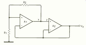
Fig.1. Active-R oscillator circuit. Frequency can be adjusted conveniently
by replacing R1 with a j-fet and varying its gate-to-source voltage.
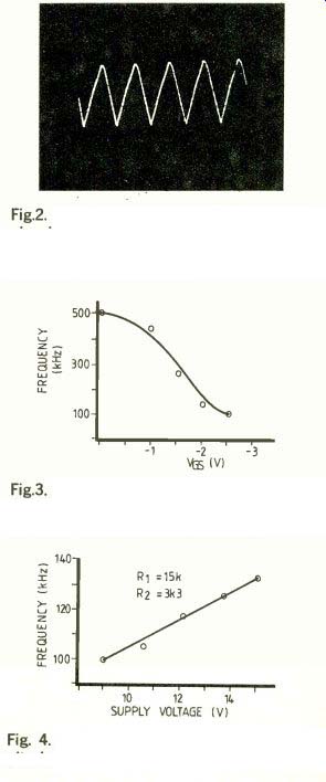
Fig.2. Output waveform at 250kHz of the circuit in Fig.1 with a j-fet
replacing R1; VGs of the j-fet is-1.5V, R2 is 3.3k1/ and the op-amp's
supply is ±10V.
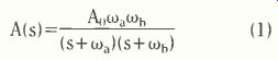
Fig. 3. Frequency of oscillation varies with the gate-to-source voltage of the j-fet.
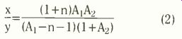
Fig. 4. Frequency can also be varied by altering the supply voltage of the op-amps.
Voltage-controlled oscillators find numerous applications in instrumentation, measurement and communication systems. The literature contains a large number of oscillator designs and analyses based on active-RC and active-R principles. The active-R design technique is, however, more attractive for monolithic IC fabrication. Our first circuit is a new voltage-controlled active-R oscillator using only two general purpose operational amplifiers and two resistors.
ACTIVE-R OSCILLATOR
The circuit is shown in Fig.1. Let the open-loop gain of the operational amplifiers be represented by the two-pole model given by
… where A the corner frequency, cob is the second corner frequency and B=A,1Wa is the gain-bandwidth product of the operational amplifier. The transfer function of the circuit can be expressed as:
x (1+n)A1A2 y (A1-n-1)(1+A2) (2)
... where n=R2/R1.
For the circuit of Fig.1. to produce and sustain oscillations, the transfer function of (2) must be equal to unity, giving:
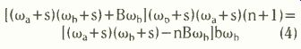
[(Wa+S)(W¡b+S)+BWb)(wb+s)(wa+s)(n+1)=1(Wa+S)(Wb+S)-nBWb)bWb (4)
By rearranging (4) and equating the imaginary part to zero, the frequency of oscillation can be shown to be:
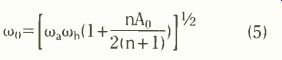
1 Wo=[WaWb(1+2(n+1))l'2 (5)
Further simplification of (5) can be obtained if nA02(n+1), giving coo= nBcub/2(n+1) (6) By equating the real part of (4) to zero and using (5) and noting that for most practical cases Wb>Wa the condition of oscillation can he shown to be approximately

A > 3n+4 co, 2(n+1) cob (7)
This condition is easily satisfied in practical operational amplifiers.
Equation 5 shows that the frequency of oscillation is a simple function of the resistance ratio n. This feature of the proposed circuit is of practical significance because the resistance ratio is effectively insensitive to temperature changes over a considerable range. Moreover, by keeping R2 constant, it is possible to adjust the frequency of oscillation simply by changing R1. By replacing R1 with a j-fet it is, therefore, possible to adjust the frequency of oscillation by adjusting the gate-to-source voltage of the j-fet.
The circuit was built and tested using the operational amplifier TL064CN and the j-fet 3N187 and fairly good sinusoidal oscillations were obtained: Fig. 2 shows a typical output waveform at 250kHz.
Figure 3 shows how the frequency of oscillation altered with the gate-to-source voltage of the j-fet. When the gate-to-source voltage was varied from 0 to-2.5V, the corresponding change in the frequency of oscillation was from 500kHz to 128kHz.
Changing the d.c. supply voltage of the operational amplifiers from ±9V to ±15V raised the frequency of oscillation from 100kHz to 133kHz (Fig.4).
MINIMUM-COMPONENT OSCILLATOR
Because of their numerous advantages, there has been considerable interest in the design of active-RC oscillator circuits with grounded capacitors. Besides a single grounded capacitor, our second circuit uses only a single resistor and a single operational amplifier. The circuit, therefore, uses the minimum number of passive and active elements (Fig.5).
Let the open-loop gain of the operational amplifier be represented by the two-pole model given by equation 1. The transfer function of the circuit can expressed as:

y-A(s) x (1+SCR) (8)
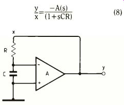
Fig.5.
Op-amp oscillator for the minimalist: for practical reasons the grounded
capacitor arrangement is very desirable.
For the circuit of Fig.5 to generate and sustain oscillations, equation 8 must equal unity. Substituting (1) into (8) and rearranging, then

(1+5CR)(Wawb+52+5(wa+Wb))=-AOWaeab (9)
The frequency of oscillation can be obtained from (9) by equating the imaginary part to zero, giving:

2 Wa+Wb (00-WaWb+ RC (10)
By equating the real part of (9) to zero and using (10) and noting that for most practical cases Wb> Wa, we can show that the condition of oscillation will be given, approximately, by:

Ao>[Wa+WaCR+WbCR,
This condition can easily be satisfied in practical operational amplifiers.
From equation (4) it follows that the frequency of oscillation is a simple function of the product RC. Therefore, by changing R or C, or both, it is possible to adjust the frequency of oscillation.
The circuit of Fig. 5 was built and tested with a 741 op-amp, polystyrene capacitors and metal film resistors. A typical waveform is shown in Fig.6.
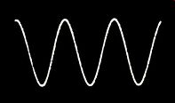
Fig. 6. Output waveform at 3kHz of the circuit in Fig.5 built with a
741 op-amp. The resistor is 19k12, the capacitor 1µF and the supply voltage
±15V.
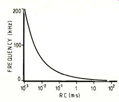
Fig.7. Altering the RC product of the circuit in Fig.5 shifts the output
frequency over more than two decades.
When the RC product was adjusted from 57 ms to 1 uS, the frequency of oscillation was found to vary over more than two decades, from 1.4kHz to 200kHz (Fig.7).
References:
M.T. Darkani, and B.B. Bhattacharyya, Generation and design of canonic grounded-capacitor variable-frequency RC-active oscillators, Proc. IEE 132 Pt.G, 1985,153-160.
R.S. Sidorowicz, An abundance of sinusoidal RC oscillators, Proc. IEE 119, 1972, 283-293; Some novel RC oscillators for radio frequencies, Electron. Eng. 39, 1967, 498-502, 560-564.
M. Sundaramurthy, B.B. Bhattacharyya, and M.N.S. Swamy, A simple voltage controlled oscillator with grounded capacitors, Proc. IEEE 65, 1977,1612-1614.
B.B. Bhattacharyya, M. Sundaramurthy, and M.N.S. Swamy, Realization of tunable RC-active oscillators using grounded capacitors and voltage amplifiers, Int. J. Circuit Theory & Appl. 8, 1980, 355-371.
R.A. Stein, Synthesis of grounded-capacitor multiport RC networks, IEEE International Symposium on Circuit Theory, 1971, 49-50.
M.S. Abougabal and B.B. Bhattacharyya, Easily integrable very-low-sensitivity active RC filter, Electron. Lett. 81972, 303-304.
H. Hribsek and R.W. Newcomb, VCO controlled by one variable resistor, IEEE Trans. on Circuits and Systems 23,1976,166-169.
R. Senani, New canonic sinusoidal oscillator with independent frequency control through a single grounded resistor, Proc. IEEE 67, 1979, 691-692;
Novel sinusoidal oscillator employing grounded capacitors, Electronics Letters 16, 1980, 62-63.
Y. Sun, Generation of sinusoidal voltage (current) controlled oscillators for integrated circuits, IEEE Trans. on Circuits and Systems 19, 1972, 137 141.
M.P. Tripathi, S.B. Roy, and D. Patranabis, Some observations on single-element control sine-wave oscillators, International Journal of Electronics, 43,1977,513-520.
N.A. Shah, and C.K. Bhat, Operational amplifier-based voltage-controlled oscillator, International Journal of Electronics 59, 1985, 649-652.
S. Kaliyugavaradan, Single-resistance-controlled RC-oscillator using a single operational amplifier, International Journal of Electronics 50, 1981, 153-155.
------------
Also see: Automatic Testing
==========
(adapted from: Wireless World , Jan. 1987)