Negative-input switching regulator
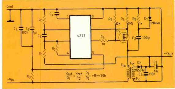
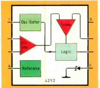
Various configurations for the RC4292 negative switching regulator are shown in the device's preliminary product specification.
Full component details are given for this negative-input to +5V regulator which works with inputs of up to-90V and delivers about 120mA.
At full load, inputs from -60 to -30V cause an output variation of 20mV; load regulation is 15mV from 10 to 120mA. One of the main features of this Raytheon device is that it operates with inputs of up to-120V so it is suitable for use in telephone line-driven supplies. At -48V input, this circuit is 60% efficient. A dual-output (-5.5V and +5V) regulator specifically for a p.b.x. off-hook supply of-48V is one of the remaining foul) circuits given in the specification.
---------------
Digitally controlled graphic equalizer
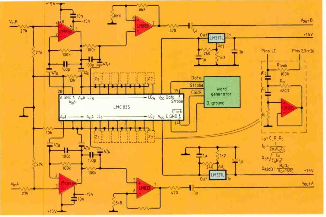
Computer control of the curve of this seven-band stereo graphic equalizer requires three digital signals--one containing serial data, one to clock the data and one to strobe data words. The circuit is one of six application ideas contained in National Semiconductor's data sheet for the LMC835 c-mos graphic equalizer with digital control in puts.
Signal-to-noise ratio of the 835 ranges from 106 to 116dB, depending on level settings, and t.h.d. is 0.0015% at 1 kHz, rising to 0.1% at 20kHz.
Gyrator component values [coming soon]
------------------------
Installation of load cells
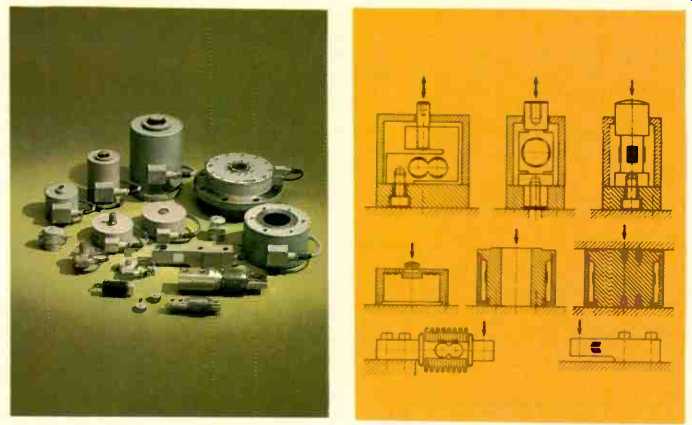
One of the load cell's chief industrial applications is the weighing of containers. Where heavy, fixed containers are concerned, load cells are particularly useful when checking the level within a container is impractical or when the volume-to-weight ratio of the container's content varies.
Electrical and mechanical considerations for load-cell installation are discussed in Hottinger Baldwin Messtechnik publication G21 03 1 e. The guide outlines how to connect cells to minimize electrical interference effects and how to mount the cells to prevent bending and torsional moments.
These diagrams show some of the load-cell variations available: black portions indicate the sensing area.
----------------
Using tag ram for content-addressable memory
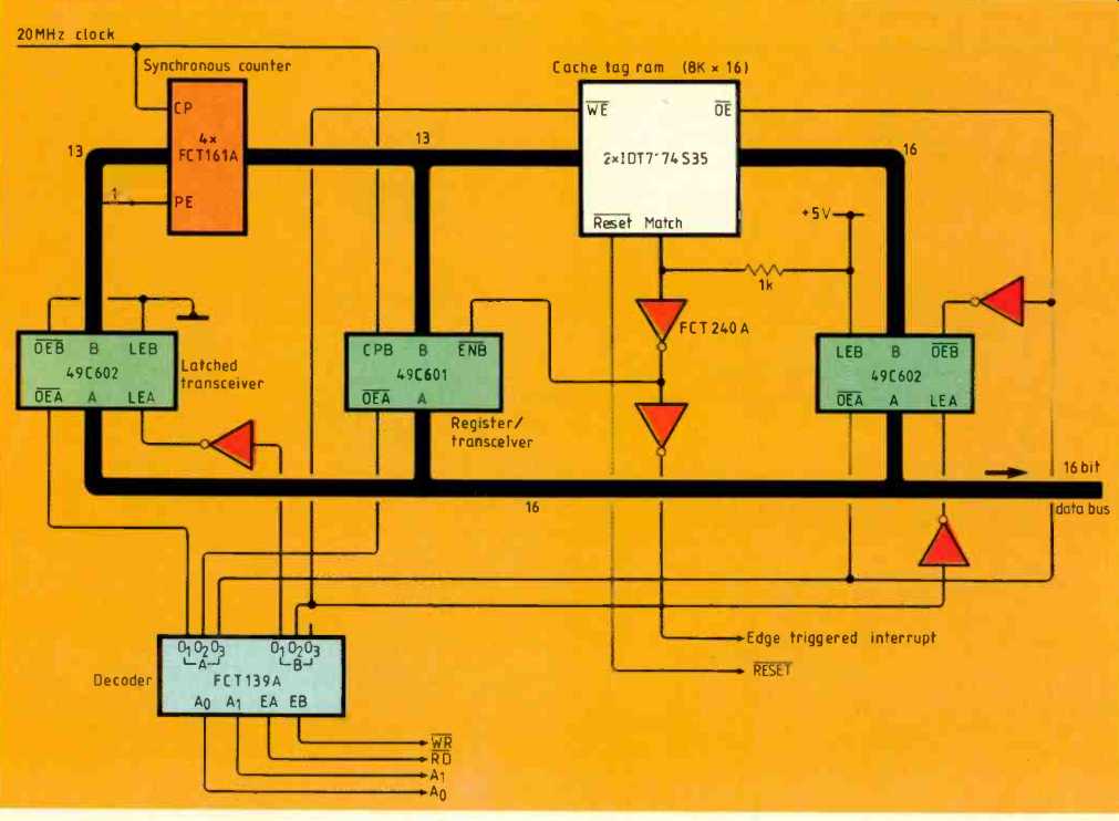
Content-addressable memory is the inverse of look-up table memory. According to IDT application note EA001, entitled Content addressable memory system using IDT7174 cache tag ram, look-up memory is analogous to a normal telephone directory and content-addressable memory is analogous to a directory indexed by telephone number.
Comparing names and addresses involves comparing large numbers of data bytes, but comparing telephone numbers' takes only one byte. Therefore content-addressable memory is useful for searching through large amounts of memory at high speed, for example in data-bases.
Within the IDT7174 cache tag ram is a high-speed comparator and 64K of c-mos memory: this combination allows data comparisons to be made in less than 37ns. The note briefly describes the tag ram and the circuit shown here.
----------------
Programmable video-timing controller
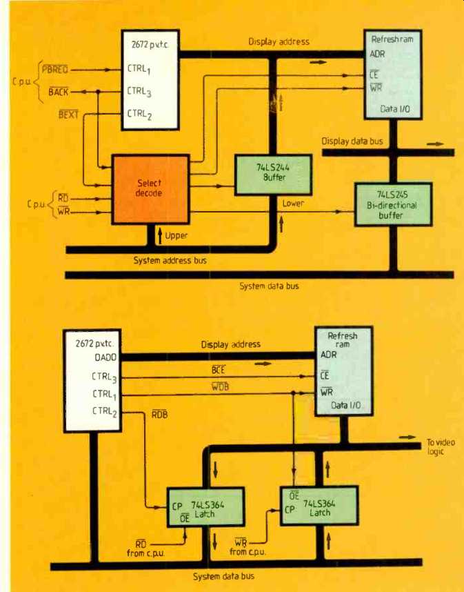
Address and data lines from the SCN2672 programmable video-timing controller connect directly to up to 16K of dynamic ram for refresh and display access. When computer address and data buses need to access the display ram for updating, the video-controller bus lines can be floated so only one set of three-state buffers is needed to avoid bus contention.
The Mullard SCN2672, designed for raster-scanning systems, has two modes. In shared mode, top, the computer and video controller share the video memory; display update addresses from the computer feed the display-ram address bus through buffers. In independent mode, bottom, display ram is addressed only via the controller; display-update addresses from the computer enter the controller through the data bus so this mode requires only data-bus latches.
Within the 2672 controller, eleven registers select display-buffer, split-screen and cursor addresses, video sync timing and double-height/underline/cursor-blink functions. Up to 128 character rows and 256 characters-per-row can be displayed; character height can be between 1 and 16 scan lines. Timing signals and various configurations in block-diagram form are given in the 23-page data sheet.
------------
Stepper motors and control systems
In ordinary AC and DC motor applications, acceleration and deceleration phases represent only a small design problem but with stepping motors, these phases are of primary importance since stepping motors spend most of their time accelerating and decelerating.
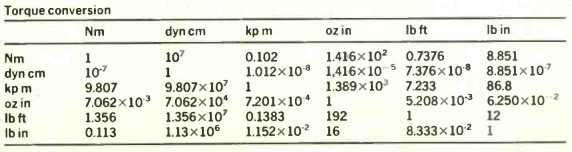
In Bulletin ST-AD from Bodine, effects of this type of 'transient-state' motor are discussed. Solutions to the problems involved are particularly Bodine oriented but the discussions of the problems are of general interest, particularly on the mechanical side. This table is from the brochure's section describing formulas relating to stepper-motor choice. There is also a section on motor-sizing calculations.
It is pleasing to see that safety aspects of choosing a stepper motor take a good pro portion of the first page of this 13-page American brochure.
(below) Torque conversion
Also see: APPLICATIONS SUMMARY (Oct. 1987)
==========
(adapted from: Wireless World , Dec. 1987)