Compact disc players are complex electronic and mechanical devices. Their reliance on special proprietary integrated circuits and zero-tolerance mechanical alignment leave the average consumer or electronics hobbyist reduced opportunity for complete home repair.
This does not mean, that doctoring the ills that beset the CD player is entirely out of your hands.
On the contrary, the simplicity and modularity of CD player design make mechanical and electronic faults very rare--assuming that the machine was well manufactured in the first place.
In this section, you'll learn what you can do when your CD player goes on the fritz, and how to go about fixing it. The emphasis is on troubleshooting the mechanical sections of the player, and plenty of flowcharts are provided to graphically show the step-by-step process of the cure for a given ailment.
FIX IT YOURSELF
Service shops for CDs report that the following causes represent by far the greatest majority over 80 percent--of warranty and non-warranty repair. The causes are listed from most common to least common.
Failure to loosen or remove the transit screw.
Disc problems (includes improper disc handling or loading, warped disc, scratched or dirty disc).
System connection (cable from CD to amp, speaker wires, etc.).
Physical abuse or accidental damage.
dirty objective lens on the optical pickup.
You can save yourself the cost of a service call, not to mention headaches and frustration, by not only following manufacturers' instructions for operating your hi-fi gear, but by caring for your discs and your player.
SERVICE POLITICS
Ordinary mechanical and electronic breakdown do occur, you can repair a number of these breakdowns yourself. Most dysfunctions can be corrected by cleaning dirty electronic contacts and switches, oiling or greasing the moving parts, repairing the occasional broken or frayed wire, and replacing worn parts like rollers, belts, and plastic gears.
Unless you have specific training and experience in working with both high speed digital and analog circuits, and have the proper servicing tools, problems with the optical system (alignment, output, and forth), as well as failed integrated circuits and other components on the circuit boards should be referred to a repair technician. More complex problems require a schematic or service manual, an oscilloscope, and a variety of specially made alignment and test jigs.
They also require additional troubleshooting and repair techniques, which are beyond the scope of this guide. If you are interested in learning more on this subject, see Appendix D for a selected list of general and specific electronic troubleshooting and repair guides.
Many manufacturers will sell you a copy of the schematic or service manual, but be prepared to spend up to $30 for it. The wait can take up to eight weeks. We provide the names and addresses of most CD player manufacturers in Appendix B.
Most CD manufacturers will not sell the test jigs and alignment tools directly to consumers. In fact, many player manufacturers won't even sell the tools to independent authorized service centers! Other than routine cleaning and checkout, along with replacement of some mechanical parts (most or all of which you can do yourself ), service centers are directed to send defective players back to the manufacturer for repair.
One exception to this rule is defects in the main printed circuit board (PCB), which holds most or all of the circuitry for processing and converting the disc data into an analog signal. These problems can often be handled in the repair shop, but they almost always entail completely exchanging the old board for a new one. In the service trade, a technician who repairs electronic products simply by exchanging a PCB is euphemistically called a ''board swapper." Technicians don't much like it (the implications in the phrase as well as the inability to get parts), but individual components and ICs are not available from the manufacturer, and they must take what they can get.
If you suspect a problem with the main PCB in your player, you may be able to get a replacement directly from the manufacturer and change the board yourself. This could save you $75 or more in labor costs. CD makers sell the boards on an exchange basis. You send in the old, defective board--along with a check or money order to cover the service fee--and they send you a good, tested board in return.
USING THE TROUBLESHOOTING CHARTS
The remainder of this section is devoted to a series of troubleshooting charts that detail the possible causes and suggested solutions for a series of common and not so common CD player ailments.
The charts are not meant to be definitive, but they should go a long way in helping you pinpoint a problem in your player. See Section 8 for an explanation on how to use and interpret the charts. You are also referred to Sections 5 and 6 on the tools and supplies of CD maintenance and repair, and how to use them. To avoid repetitive solutions sections and paragraphs have been numbered. The flowcharts will refer back to solutions Rather than restating them in the section paragraphs.
To prevent overcomplicating the charts, they have been designed to apply specifically to ac operated home players. Many of the same problems, causes, and solutions will apply to all three types of players--home, portable, and car--but troubleshooting techniques may differ in certain situations.
You can still use the troubleshooting charts to diagnose most problems in portable or car units, however, because the basic reasons behind the fault will be similar. For example, a car CD player does not have an ac cord, so you would not test its cord if you are having trouble in operating the unit. But you would test the power line supplying the 12 volts dc to the player, in a similar manner as you would an ac cord.
The reason for leaning toward the home ac operated units is that they are considerably easier to maintain and repair than the portable and car versions.
Look to the Simple Things First
In using or looking over the charts, you may find that some of the possible causes may seem overly simplistic. The biggest mistake you can make in servicing your compact disc player is overlooking the obvious. If something doesn't work, odds are, it’s a simple cause with an equally simple solution. Repairs are a lot less expensive and time consuming because of it.
List of Charts
Here are the troubleshooting charts, in their order of presentation. The charts are numbered for cross-reference. Within the charts, the steps (or levels) are numbered, which correspond to numbers in the text. Unless otherwise specified, all troubleshooting procedures and tests should be done with the player turned off, and unplugged or removed from the power source. Most manufacturers suggest you reinstall the transit screws before disassembly. Be sure to remove or loosen the screws again when testing or moving the player.
9.1. When a player does not turn on, the cause is almost always mechanically related. (This goes for all three main types of compact disc players.)
9.1A. 1 The first logical step is to insure that it is getting power from the ac wall source. Make sure that the cord is plugged in, and that the polarized plug is inserted properly. Do not defeat the purpose of the polaris ed plug by filing or cutting the wide prong.
9.1 A.2 In homes equipped with switched outlets, (you flick a wall switch to turn the outlet on and off), the switch controls both outlet receptacles, other times just one. If the player is plugged into a switched outlet, make sure that it is turned on.
To rule out the possibility that the problem originates in the wall outlet and not in the player, plug a lamp into the socket and see if the lamp works. If the lamp seems dim, check the voltage at the outlet with a volt-ohm meter. It should read between 108 and 125 volts ac (117 is average). Be absolutely sure that you follow all safety precautions when testing the ac voltage or you may receive a serious shock.
9.1A.3 If the power cord is plugged into an amplifier or receiver, check to see if the outlet you have chosen is switched. Some amplifiers have a built-in switched outlet. The outlet is activated when the amplifier is turned on. If the outlet is un-switched (and will usually be labeled as such), the outlet is active at all times as long as the amplifier is plugged in. If the CD player is plugged into the amp, be sure that the amplifier itself is plugged into the wall socket. Try the lamp or meter test if you are unsure of the power outlet at the amp.
9.1A. 4 Most players incorporate a transit screw hat locks the moving parts in the player into place, preventing them from being knocked out of alignment during shipment. With a few players, leaving the transit screw in place, or failure to loosen it all the way, will prevent the machine from turning on. Be sure the transit screw is loosened or re-removed according to the manufacturer’s instructions. There may be two or more transit screws, each locking down a different internal part, make sure you get them all.
9.1A.5 Players with timers will usually shut down when in timer mode (the timer plays a disc starting at a specific time of the day). Follow the manufacturers instructions on deactivating or resetting the timer.
9.1A.6 If your player is equipped with a fuse, remove it and visually inspect it. If you can’t tell that the fuse has blown, use a meter to check continuity. Attach the leads to either side of the fuse.
If the fuse is good, the meter will read 0 ohms. An infinite reading indicates a bad fuse.
Note: Some compact disc players use current limiting fuses. These are like regular fuses, except they use an internal resistor to limit the current flowing through them. If the fuse has an internal resistor (which can be easily seen through the glass capsule), the meter reading will register the value of the resistor. In most cases, the value will be low, under 1,000 ohms.
9.1 A.7 After checking the ac sources, transit screw(s), timer, and fuse, inspect all power cords for cracks and other signs of wear. A badly worn or damaged cord can cause a number of problems.
A short will blow fuses (either in the house or in the player ); an open line will prevent the ac from reaching the player.
Check the power cord using a meter. A short will register 0 ohms (or a low reading) when the test leads are connected across the two prongs of the cord. An open will register infinite ohms a very high reading) when the test leads are connected to the prongs and internal wiring of the player, as shown in Fig. 9-1. Test both prongs.
9.1B.1 The power wiring inside your player may be faulty. Open the player and check the connections leading to the power switch. Check for shorts and open circuits using the meter. Normally, only one side of the incoming ac will be connected to the switch. The other side will connect directly to the power transformer.
9.1B.2 If the wiring to the switch tests okay, try the wiring leading from the switch and to the inputs of the power transformer (called the primary). Also test the wiring from the output of the transformer (called the secondary) to the power supply model or main PCB. A sample schematic diagram of the power supply circuits from a typical CD is shown in Fig. 9-2.
To test that the transformer is delivering power, plug in the machine (if it is safe) and turn it on. With the meter set to read ac volts, with a range of no less than 25 or 50 volts, connect the test leads to the outputs of the transformer. Without a schematic, it may be difficult to make sense of the readings, but generally, you should get reading of 6 to 24 volts when connecting the leads to any of the wires.
The power transformers used most CD players have different tap offs, so applying the leads at different tapoffs will yield a wide variety of results. You can be fairly sure the transformer is working properly if you get some readings when the meter is connected to the most of the secondary wires. Be sure to avoid the primary wires, as they carry the full 117 Vac from the wall outlet.
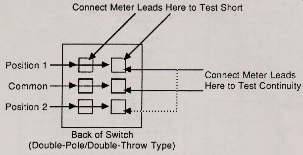
9.1B.3 It’s easy to forget that switches are mechanical in nature, and they can get broken, dirty, and corroded. Test the Power switch to make sure that it works properly. Connect the test leads of the ohm-meter to either side of the switch terminals. The meter should read 0 ohms when the switch is in the on position, and infinite ohms when the switch is in the off position. If the switch is the double pole type-two sets of switch contacts inside instead of just one-test each set separately.
(Fig. 9-3)
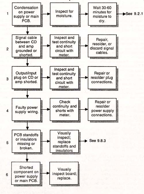
9.2. It is often harder to troubleshoot a CD player when the machine turns on but doesn’t play; however, at least you can rule out problems in the power supply, fuses, on/ off switch, and all that other stuff.
9.2.1 Taking a compact disc player from the cold damp outside air to the warm inside air can cause condensation to form on the internal components. A few CD home players (and many portable and car models) have a dew sensor that prevents the machine from operating when there is condensation present. If you suspect condensation, visually inspect for moisture and wait 30 to 60 minutes for it to evaporate. You can speed up the drying process somewhat by using a hair blow dryer. Keep the dryer on low or no heat.
9.2.2 Some players are built with a cabinet interlock switch, which may be broken or open. All or some of the player is shut off when the top cover is removed. If the cover is off, look for a switch.
Manually depress it and see if the player turns on.
To test the switch, make sure the player is off and unplugged. Use the volt-ohm meter to test the continuity of the switch. With the leads of the meter connected to either terminal of the switch, the reading should be 0 ohms when the switch is closed, and infinite ohms when the switch is open.
9.2.3 You may not be able to control the operation of the player if one or more of the front panel switches are dirty or broken. If only one switch is affected, you may be able to cycle the player through its other operations.
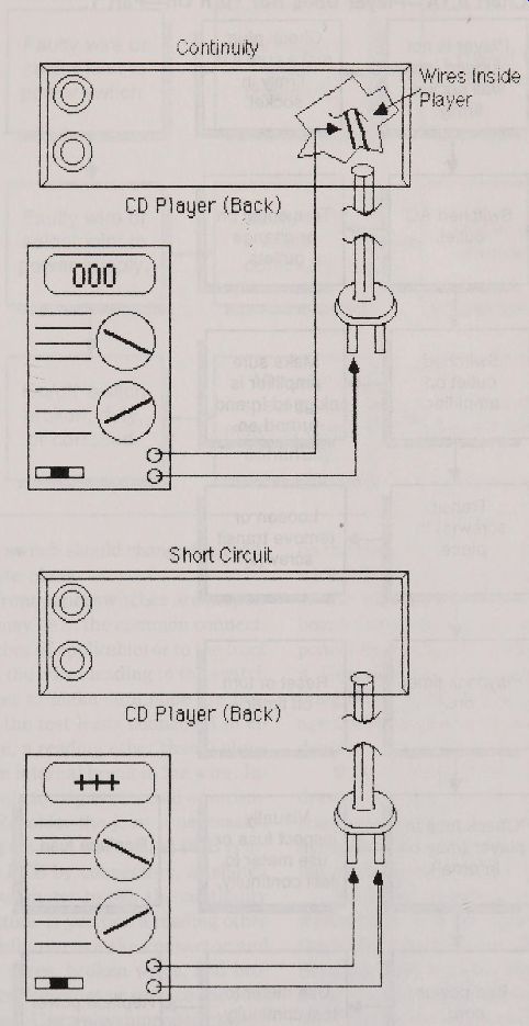
Fig. 9-1. Use a VOM to test continuity and short circuits in the ac cord.
========
Player Does Not Turn On Part 1.
Chart 9.1A 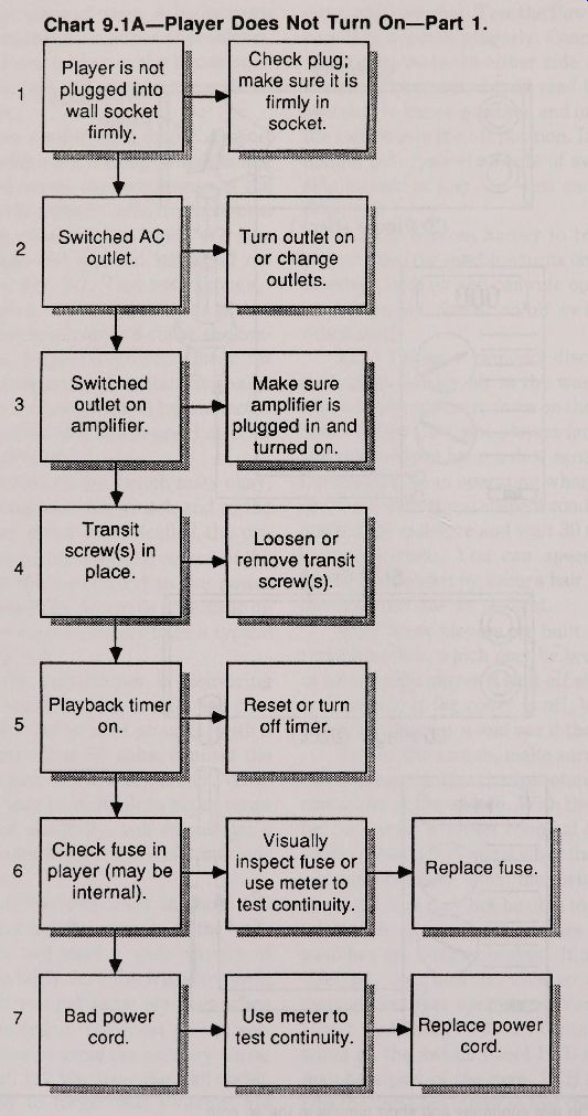
Check plug;
Player is not make sure it is plugged into firmly in wall socket AS socket.
switched AC Turn outlet on 5 X outlet or change. outlets.
....
switched Make sure outlet on amplifier is amplifier. plugged in and turned on.
Transit Loosen or screw(s) in remove transit place.
screw(s).
Playback timer Reset or turn v off timer. on.
Check fuse in inspect fuse or Replace fuse.
player (may be.... use meter to. internal).
test continuity.
Bad power
Use meter to
Replace power test continuity. cord
Chart 9.1B Player Does Not Turn On Part 2.
Faulty wire or Use meter to
Repair or solder joint to check.
resolder.
power switch. continuity.
Faulty wire or Use meter to
Repairer solder joint to check resolder.
continuity.
power supply.
Visually.
Clean or inspect or use broken, dirty, replace switch, meter to check. or corroded.
continuity.
========
You can isolate that switch by finding its solder contacts or connecting wires on the switch panel PCB (the switch panel may be a part of the main PCB in some players).
Use the volt -ohm meter to test the continuity of the switch. Pushing the switch should change the reading from 0 to infinite ohms.
9.2.4 If all the front panel switches are inoperative, the problem may lie in the common connecting wire to the switches (if applicable) or to the front panel PCB. Test all the wires leading to the switch panel with the meter to make sure none are broken or loose. With the test leads connected to either side of the wire, a reading other than 0 ohms is an indication of an internal break in the wire. Inspect the solder points for signs of a cold or incomplete solder joint. Resolder the joint if necessary.
With many players, the front panel PCB is attached to the main PCB by connectors, as shown in Fig. 9-4. Use your meter to test the continuity between the connectors. If you find a reading other than 0 ohms, carefully remove the connector and inspect it for loose wires, broken wires, and broken or dirty contacts. Resolder or replace the connector if it is damaged. Use a recommended cleaner to clean contact points.
9.2.5 If the problem still persists, the next logical step is to examine the wires and components on the main PCB. Are there any obviously broken wires? Test with a meter to be sure. Look closely at the capacitors and resistors mounted on the board. Occasionally, you can spot a burned out component by looking for black char ring on and around it. Generally, you cannot spot a blown transistor or integrated circuit in this manner because the dam age does not usually extend to the exterior of the device.
9.3. If you find that the disc loading door or drawer will not open or close, under no circumstances should you try to force the drawer or door manually. Doing so may seriously damage the loading mechanism or seriously bend a catch or latch.
9.3.1 An object of some type, including a warped disc, could be obstructing the free path of the loading drawer / door. Remove the top cover of the player and examine the loading mechanism. If a disc is on the spindle, remove it by gently lifting the flapper (clamping lever ) and easing out the disc.
Examine the disc for warpage. Turn the machine on and try opening the drawer / door again.
If the drawer / door still won't operate, inspect
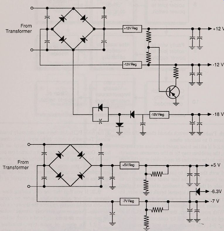
Fig. 9-2. Schematic of the power supply circuit used in a typical CD player.
Note that six different voltages are fed to different points on the player’s
PCB.
Fig. 9-3. Connect the probes of the meter as shown to test for continuity
or shorts in a double-pole/ double-throw switch. Connect Meter Leads Here
to Test Short -Connect Meter Leads Here to Test Continuity -Back of switch
(Double-Pole/ Double-Throw Type)
the path of the mechanism, including all gears, cams, slideways, and other parts in and around the loader. Carefully remove any objects that may have lodged in place.
9.3.2 When you push the Open / Close button, does the loading motor operate? If it does, but nothing happens, suspect the belt that connects the mot or to the loading mechanism. Belts can break or slip off the metal or plastic pulleys. Look at the belt as you depress the Open / Close switch. If the motor shaft turns, but the belt doesn't budge, the belt may be too loose or may be slippery from oil or grease build-up. Inspect the belt and clean it if necessary.
A number of machines use plastic gears to drive the loading mechanism from the motor. A gear is mounted on the motor shaft, and meshes with a straight toothed rail. When the motor shaft turns, the gear inches the loading mechanism along the rail, thus opening the drawer or door (Fig. 9-5). Inspect the gear and rail to be sure that none of the teeth are broken and that the gear teeth are meshing properly.
9.5.5 Even if the loading mechanism looks fine, the gears and rails may still bind against one another. Would oiling or greasing help? Apply a small dab of grease on the gear surfaces or oil to shafts and levers.
9.3.4 If the motor does not turn when you depress the Open/ Close button, it may not be getting the command to do so. Check the Open/ Close witch first, to make sure that it hasn’t gotten dirty, broken, or corroded. To test the switch, connect the test leads of the ohm-meter to either side of the witch terminals. The meter should alternate between 0 and infinite ohms when the switch is pushed.
Keep an eye out for cracked or pinched wires leading to the switch, as well as poor solder joints.
Test the joints and wires using the meter, as usual.
Opens and shorts are indications that the wiring is ad and must be repaired.
3.5 The wires from the Open/ Close switch out es back to the main PCB, and eventually is connected to the system micro-processor. You can test the wiring leading from the microprocessor and back out to the disc loading motor. Inspect these wires carefully and look for obvious damage. Use the volt-ohm meter to test continuity. You should et a reading of 0 ohms when the test leads are connected to either end of the wires. Broken or cold older joints on the motor terminals should be de-soldered.
==============
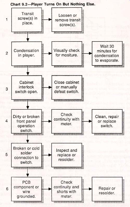
Player Turns On But Nothing Else.
Chart 9.2 1
Transit Loosen or 2 screw(s) in remove transit place screw(s).
Wait 30..
.. Visually check Condensation minutes for 5.
for moisture. in player. condensation s
. it to evaporate.
Close cabinet
Cabinet.
or manually interlock.
.Tl defeat switch. switch open.
Check
Clean, repair
dirty or broken continuity with front panel or replace meter.
operation switch.
switch.
Broken or cold Inspect and...
solder replace or connection to resolder.
. a switch..
at Check
PCB .
continuity and component or
Repair or shorts with wire resolder.
grounded. meter.
==============
Fig. 9-4. In most players, the front panel controls and indicators are mounted on a separate PCB. The front panel and main PCBs are electrically connected using wires or flexible printed wire boards (PWBs)
To ensure that the proper drive signals are being applied to the motor when the Open/Close witch is depressed, connect the volt-ohm meter to both motor terminals (Fig. 9-6). Select the dc volts function on the meter, with a range of no less than 12 volts. With the player plugged in and turned on, depress the Open/Close switch once. With most machines, your meter should read a voltage (it may be as small as 3 volts but as high as 12 volts).
9.3.6 If no other defects can be found up to this point, the problem may lie in the loading motor itself. You can test the motor by connecting a "C" or " D" size battery to the motor terminals, as illustrated in Fig. 9-7. The polarity of the battery determines which direction the motor turns, so if the motor seems to labor when power is applied in one polarity, reverse the connection to the terminals and try again.
9.4. It’s aggravating when the CD plays a disc for only a few seconds or minutes, then either turns off mysteriously, or comes to a grinding halt. Fortunately, the problem is almost always mechanical in nature and is often easily corrected.
9.4.1 A disc that’s been scratched may play for a while then abruptly stop. This can happen especially if the scratch is a deep one, and throws the pickup seriously out of tracking or focus. With a number of players, a complete and irrecoverable loss of tracking and focus will cease playback.
Likewise, a warped disc may play for a while. Then, as the amount of warpage increases as the pickup moves to the outer edge of the disc, the pickup can no longer keep the disc in track or focus. If a disc won’t play, inspect it, and if possible clean or repair it. A seriously warped or scratched disc is not repairable and must be discarded.
9.4.2 A dirty objective lens can prevent the laser from tracking or focusing the disc. If the tracking or focus error spans many thousands of bits, the system microprocessor in the player may stop playback. If the problem persists with many discs, a dirty lens may be the cause. Inspect and clean the objective lens.
9.4.3 An open or defective interlock switch may prevent the CD from playing more than just a few seconds of the beginning of the disc. The system microprocessor senses that the interlock switch is open, and stops playback. Interlock switches are typically located in the disc loading drawer / door mechanism, and sometimes in the cabinet.
---------
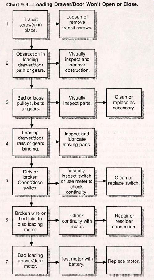
Loading Drawer / Door Won't Open or Close.
Chart 9.3
========
Loosen or.
Transit
remove. A 1 screws) in
transit screws.
. place.
Visually Obstruction in
inspect and loading drawer / door remove
obstruction.
or gears.
Clean or
Visually Bad or loose
replace as pulleys, belts inspect parts.
necessary.
or gears.
Loading Inspect and
drawer / door lubricate rails or gears moving parts.
binding.
Visually dirty or
inspect switch
broken
Clean or
or use meter to
Open/ Close
replace switch.
check
switch.
contmuit
Broken wire or
Check
Repair or
bad joint to
continuity with resolder A
disc loading
connection. meter.
Test motor with
. drawer / door
Replace motor
battery.
motor.
=========
Be sure that all interlock switches are properly closed. If you are testing the player with the top cover off, look for a safety interlock switch and close or defeat it (you can defeat it by attaching a jumper between its terminals, as shown in Fig. 9-8).
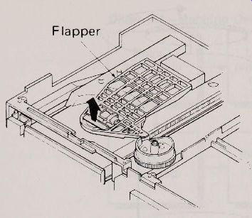
Fig. 9-5. The location of the flapper in a drawer-type disc loading mechanism.
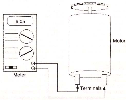
Fig. 9-6. How to test the voltage level reaching the disc loading motor.
Interlock switches in the disc loading mechanism should be closed if a disc is properly inserted.
Test the interlock switches to make sure that they work properly. Connect the test leads of the ohm-meter to either side of the switch terminals.
The meter should read 0 ohms when the switch is in the on position, and infinite ohms when the switch is in the off position. For testing purposes, you can over ride a broken switch by connecting a jumper between its terminals (see the figure above).
For normal operation, a dirty or broken switch should be cleaned or replaced.
9.4.4. Insert a disc and press play. Listen for the sound of the pickup motor turning. If motor turns but the pickup does not move, check pulleys, belts, rollers, or gears for signs of wear and/ or excessive slippage. Also check for obstructions or foreign matter that may prevent the pickup from moving freely.
9.4.5 The speed of the disc during playback is carefully monitored by the system microprocessor, and any fluctuations are adjusted during playback to provide highly accurate disc rotation speed in most players, the disc spindle motor attaches to the disc spindle by a pulley or belt. If the pulley or belt is worn, cracked, broken, loose, or oily, the spindle may move in a herky-jerky fashion, and the system microprocessor may not be able to correct for the fluctuations. When the playback speed exceeds certain upper and lower limits, the microprocessor will cease playback.
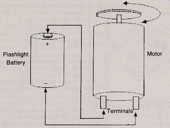
Fig. 9-7. Testing the disc loading motor with a flashlight battery. The
polarity of the wires determines the direction of motor rotation.
With the cover of the player off, and a disc loaded, press play and watch the drive motor, pulley, belt, and spindle. You should be able to see any mechanical defects. If the belt seems like it’s slip ping, apply some non-slip cleaner to it, or replace it with a new one.
9.4.6 The compact disc system depends greatly on the light output of the laser in the optical pickup.
If the light output gets too high or low, playback is impaired and the data from the disc may not properly reach the player electronics. A laser diode that gets too hot acts erratically, and its light output is not steady. In these cases, the preamplifier and EFM demodulator cannot accurately process and decode the disc data, and the player is forced to shut down.
Many players, particularly the models designed for the car, have a laser overheat circuit that ceases playback. If your player has such a circuit, and you suspect the laser diode may have got ten excessively hot, turn the player off for 30 to 60 minutes, and try again. Should the player get unusually warm quickly, it may be suffering from another problem.
See Chart 9.17 for more details.
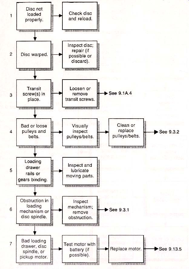
9.5. Diagnosing a disc spindle that doesn't turn when you push the Play button is a rather straightforward procedure. Compared to many CD player problems, however, there are a number of possible faults--all the way from an improperly loaded disc to a bad laser pickup.
9.5A.1 First make sure that the disc is loaded properly (with the mirrored side down) and that the door closes all the way. While the disc is out, inspect it for obvious warpage and heavy scratches.
9.5A.2 A warped disc may prevent the loading mechanism from retracting all the way. A malfunction in the mechanism itself also keeps the drawer / door from closing completely. Unless the drawer / door mechanism is fully retracted, the player will not go into Play mode, and the motor spindle will not spin. If the disc shows no sign of damage, check to make sure that the loading drawer / door is closing as it should. You may need to remove the top cover of the player to inspect the loading mechanism.
====================
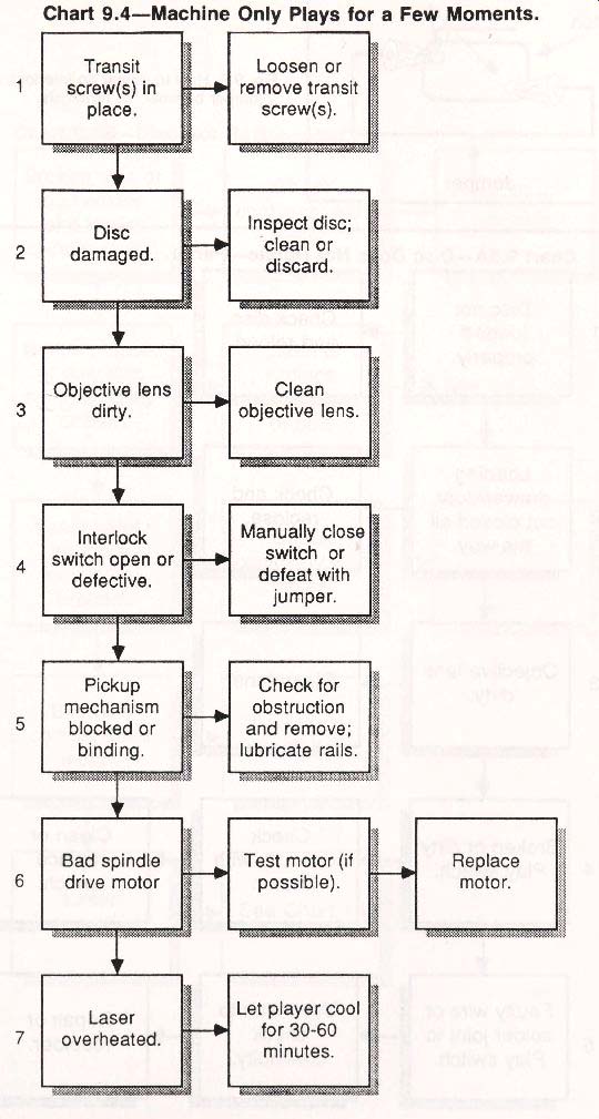
Chart 9.4 Machine Only Plays for a Few Moments.
-----
Transit screw(s) in place. is Disc damaged.
Objective lens dirty.
Interlock switch open or defective.
Pickup mechanism blocked or binding.
Bad spindle drive motor
Laser overheated.
Loosen or remove transit screw(s).
Inspect disc; 3 clean or discard.
Clean 2 objective lens.
Manually close switch or defeat with jumper.
Check for obstruction. and remove; lubricate rails..
Test motor (if possible).
Let player cool for 30-60 minutes.
Replace motor.

-------Fig. 9-8. How to defeat an interlock switch by connecting a jumper between its terminals.
===============
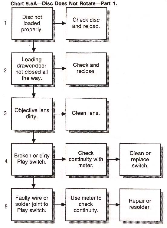
Part 1. Disc Does Not Rotate Chart 9.5A
Disc not loaded properly.
Loading : drawer / door not closed all the way.
Objective lens. dirty.
Broken dirty Play switch.
Faulty joints to Play switch.
Check disc and reload
Check and reclose.
Clean lens.
Check continuity with meter.
Use meter to check continuity.
Clean replace. switch.
Repair or resolder.
-------Chart 9.5B Disc Not Rotate Part 2.
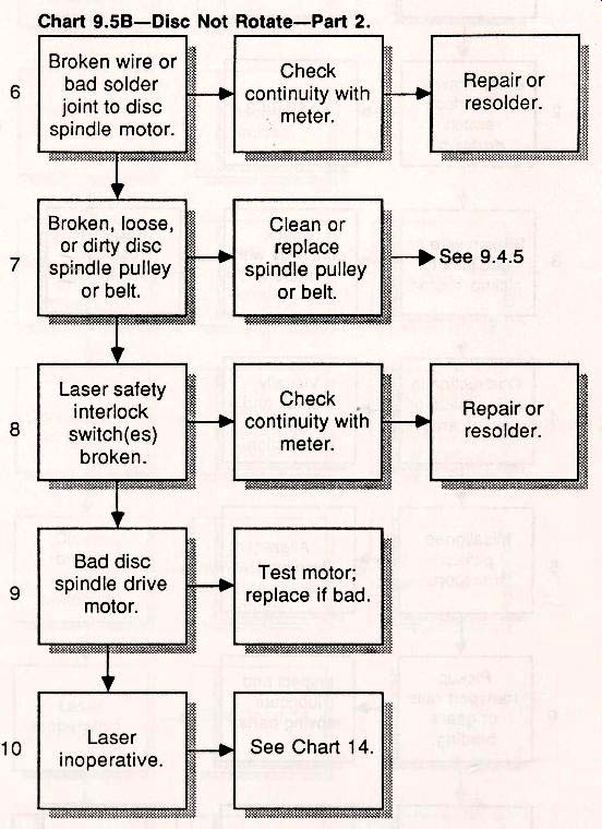
Broken wire or bad solder joint to disc spindle motor.
Broken, loose, or dirty disc spindle pulley belt. Laser safety interlock switch(es) ken.
Bad disc spindle drive motor.
Laser inoperative.
Check continuity with AS A meter.
Clean or replace spindle pulley. or belt.
Check continuity with meter.
Test motor ; replace if bad.
See Chart 14.
Repairer resolder.
. See 9.4.5 A Repair or resolder.
------------
Unit Starts But Does Not Play Disc.
Chart 9.6
Transit screw(s) m 1 place Disc, drawer, or interlock switch problem.
Broken wire or bad joint to motor.
Obstruction in pickup slide or swing arm.
Misaligned pickup transport.
Pickup transport rails or gears binding.
Bad pickup
Remove or loosen screw(s).
See Chart 3.
Check continuity with meter.
Visually inspect and obstruction. transport.
Inspect and lubricate.
moving parts.
Test motor with.
Repair or resolder connection.
Replace motor.
-------------
Chart 9.7 Player Does Not Respond to Some or All Front Panel Controls
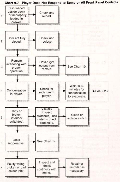
Disc loaded upside down or improperly 1 loaded in drawer.
Door not fully closed.
Remote interfering with proper operation.
Condensation in player .dirty or broken interlock switch(es).
Laser inoperative.
Faulty wiring, broken or bad solder joint.
Check and reload.
Check and reclose.
Cover light output from remote.
.Check for moisture in
aver.
Visually. inspect
switch(es); use meter to check continuity.
See Chart 14.
Inspect and check continuity with meter.
See Chart 10.
Wait 30-60 minutes for condensation to evaporate.
.. Clean or switch, replace
Repair or resolder as A necessary.
--------------------------
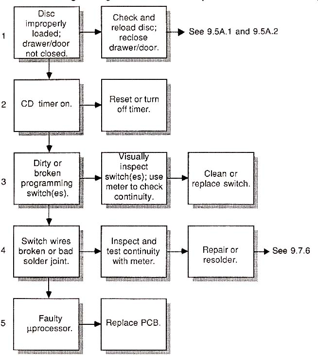
Chart 9.8
Programming Functions Do Not Respond or Do Not work.
------------------
Chart 9.9
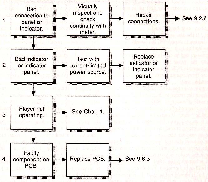
Front Panel Indicators Not Functioning.
------------
9.5 A.3 A dirty objective lens might prevent the
laser diode from properly tracking and focusing the disc. If the disc spins for a few moments, then stops, even after pushing the Play button, it’s a good indication that the problem lies within the optical pickup mechanism. Later steps in this flowchart deal with faults in the optical pickup, but the first course of action is to clean the lens.
9.5A.4 switches can get broken, dirty, or corroded.
Test the Play switch to make sure that it works properly. Connect the test leads of the ohm meter to either side of the switch terminals. The meter should read 0 and infinite ohms when the Play switch is depressed. If pushing the Play switch doesn't yield these results, it may be dirty or the contacts inside broken.
If the contacts are not sealed, spray a bit of electrical contact cleaner inside the switch. You can be fairly certain that the problem is limited to just the Play switch (and/ or its wiring) if the other front panel controls operate properly.
9.5A. 5 While at the Play switch, look for bro ken wires and faulty solder joints. Check the connections at the switch (usually direct-soldered to the front panel PCB) and the wires that lead to the main PCB. Check the wires themselves for open circuits using the volt-ohm meter. With the test leads connected to either end of the wires, the meter should read 0 ohms. If it does not, it is an indication that the wire is broken inside its insulation. Replace it with a new wire.
The wiring harness connecting the front panel PCB and the main PCB may be the flexible membrane type (called a printed wire board, or PWB). The connecting wires are actually copper bands, or traces, glued onto a flexible mylar base. These flexible ribbon connectors can be easily damaged if abused, and are extremely difficult to repair. If you suspect a broken trace on the ribbon, double check the continuity using a volt -ohm meter. A faulty ribbon must be replaced.
9.5B.1 If the disc spindle does not move when the Play button is depressed, the spindle motor or the wires leading to it may be defective. For now concentrate on bad wiring to the disc spindle motor. Locate the motor and find the wires leading from it to the main PCB. Visually examine the wires and motor terminals and look for obvious breaks or bad solder joints.
Use your volt-ohm meter to test that the wires leading from the motor to the main PCB are good and that Nothing is shorted. With the test leads connected to either end of each motor wire, the reading should be 0 ohms. If you get a reading of infinite ohms, it is an indication that there is an internal break in the wiring or cold soldering joints. Replace the wire or resolder the joint as necessary.
Now connect the test leads across the motor terminals (many motors will have only two terminals, but if the motor in your player has more, refer to a schematic; the other leads are for the motor’s built-in tachometer ). You should get a low reading, but it should not be 0. If the reading is 0 or over 1,000 ohms, it is an indication that either the motor is burned out, or that there is a short in the wiring on the main PCB. You can usually iso late problems in the motor by disconnecting it from the main PCB. Most players use snap-on connectors that can be easily removed and replaced.
9.5B.2 Many players are built with interlock switches that prevent the laser from turning on and subsequent playback if a disc is not loaded into the tray or if the top cover has been removed. If the open, depress the switch to close the outer lock loop.
If the cover is on, and a disc is properly loaded in the tray, the fault may lie in a broken interlock switch. To test a switch, make sure the player is off and unplugged. Use the volt-ohm meter to test the continuity of the switch. With the leads of the meter connected to both terminals of the switch, the reading should be 0 ohms when the switch is closed, and infinite ohms when the switch is open.
The interlock switches for the disc loading mechanism are usually located along the length and back of the sliding mechanism.
9.5B.3 Check for excessive play in the motor shaft. Grasp the shaft and rock it back and forth.
Any noticeable amount of movement is a good indication that the bearings in the motor are worn out.
If this is the case, the motor must be replaced.
Even if the motor shaft checks out, the motor itself may be bad. You can test the motor with your ohm-meter. Follow the procedure given in step 6 of this flowchart.
9.5BA If the laser is inoperative, for just about any reason, the disc spindle may not rotate, or only for a few seconds, see Chart 9.14 for details.
9.6. If disc spindle turns but the machine refuses to play the disc, there is likely a problem in the optical pickup or pickup mechanism. Note that this symptom is not the same as when the unit plays a disc but no sound comes out. You can easily distinguish between the two if the player has an elapsed time indicator. If the indicator advances each second as it should, but no sound comes out, refer to Chart 9.11. If the indicator stays on 0:00, or stops at some point even though you have not pressed the Pause button.
9.6.1 A damaged disc, or a disc inserted upside down, will also prevent playback. Similarly, play back will not begin if there is a problem with the drawer / door loading mechanism or interlock switch. Refer to Chart 9.3 for troubleshooting details.
9.6.2 The optical pickup is operated by a motor (and in some cases a coil), which passes the assembly across the disc. A broken wire or a bad solder joint to this motor or coil will prevent proper operation of the pickup. Visually inspect the wiring at the motor / coil, and note any cold soldering joints.
Use your volt-ohm meter to test that the wires leading from the motor / coil to the main PCB are good and that nothing is shorted out.
With the test leads connected to either end of each wire, the reading should be 0 ohms. If you get a reading of infinite ohms, it is an indication that there is an internal break in the wiring or of cold joints on the solder terminals. Replace the wire or resolder the joint as necessary.
Connect the test leads across the motor / coil terminals (most motors and coils will have only two terminals). You should get a low reading, but it should not be 0. If the reading is 0 or over 1,000 ohms, it is an indication that either the motor is burned out, or that there is a short in the wiring or on the main PCB.
9.6.3 An object that blocks the free movement of the pickup assembly will prevent it from scanning the disc. Visually inspect the pickup transport mechanism and look for foreign objects, loose components, and other obstructions.
9.6.4 Slide (or sled) pickups are mounted on a pair of rails, and travel back and forth along the rails while the player reads the disc. If these rails have become misaligned, the pickup may jam and fail to move. If the rails look bent, or the rails are no longer parallel, the player must be serviced. The alignment of the rails is critical, and almost always involves using a special alignment tool.
9.6.5 The slide pickup may be frozen along the track because the transport gears are binding. Visually inspect for loose parts and tight en them (doing so may require realignment ). Lubricate the gears if necessary.
9.6.6 A pickup that never budges may be caused by a faulty pickup motor or coil. If the pickup is operated by a motor, check for excessive play in the motor shaft. Grasp the shaft and rock it back and forth. Any noticeable amount of movement is a good indication that the bearings in the motor are worn out. If this is the case, the motor will need to be replaced.
Even if the motor shaft checks out, the motor itself may be bad. You can test the motor with your meter, using the procedure given in step 3 of this flowchart.
9.7. Failure to respond to some or all of the front panel controls is often a mechanical fault, but it can also be caused by the electronics on the main PCB. If only some of the switches are affected, the problem might lie in the switches themselves, or the functions associated with the switch (optical pickup with the Play button is depressed, for example). If all of the switches do not respond, refer to charts 9.1 through 9.6.
9.7.1 If the disc is loaded upside down, or is off-center on the disc spindle, the front panel controls may not appear to work properly. Remove the disc and reinsert it. A damaged or warped disc may also cause the controls to behave erratically.
9.7.2 The disc loading drawer / door must be completely closed or the front panel controls will not function. Many players incorporate internal safety interlock switches that close only when the loading mechanism is completely closed. The switches may also be dirty or broken. See step 5 in this troubleshooting chart.
9.7.3 If your compact disc player has a remote control, it may be overriding the front switches. To rule out the possibility of a faulty remote control, remove its batteries, take it to another room, or if the control is the wireless infrared type-cover up the end to block the light. If the control is the wired type, disconnect it from the player. Refer to Chart 9.10 if disabling the remote frees the operation of the front panel controls on the player (it is an indication that the remote is faulty).
9.7.4 Given the right set of circumstances, switches can get broken, dirty, and corroded. Test the switch to make sure that it works properly. Connect the test leads of the ohm-meter to either side of the switch terminals. As you depress the switch, the meter should read either 0 ohms or infinite ohms. If not, it is an indication that the switch is faulty.
Unsealed switches can be cleaned using an electrical contact spray cleaner. Liberally squirt the cleaner inside the switch. Broken switches must be replaced.
9.7.5 The system microprocessor in the CD player might ignore the commands from the front panel switches if the laser diode is not working properly. If you suspect that this may be the case, refer to Chart 9.14. In this instance, all of the front panel controls are generally inoperative.
9.7.6 If the switches themselves check out, the problem may be caused by faulty wiring. Carefully inspect the wiring leading to and from the front panel control switches. Look for obvious breaks, kinks, and cold solder joints. Use a meter to test the continuity of all affected switches.
The wiring harness connecting the front panel PCB and the main PCB might be the flexible membrane type. The connecting wires are copper bands that are glued onto a flexible mylar base. These flexible ribbon connectors can be easily damaged if abused, and are extremely difficult to repair. If you suspect a broken trace on the ribbon, double check the continuity using a volt -ohm meter. A faulty ribbon must be replaced.
8. Most mid to high-end CD players incorporate a programming function, where you can select specific tracks for playback. With most players, you can program the tracks to play in a certain sequence. The programming feature is controlled either by the System microprocessor or a special sub-processor. In most cases, programming problems are caused by mechanical defects, and can be readily repaired.
8.1 Compact disc players with built-in timers may ignore the programming sequence you enter if the timer is on. Turn the timer off then try the programming buttons.
8.2 The switch(es) that control the programming functions may be broken, dirty, and corroded.
Test all the switches to make sure they work properly. Connect the test leads of the ohm-meter to either side of the switch terminals. When the switch is depressed, the meter should alternate between 0 and infinite ohms. If it does not, there is a good chance that the switch under test is defective. If the switch is unsealed, you can clean its contacts with an electronic contact cleaning spray.
8.3 If the switches and wiring check out, it’s safe to assume the problem lies further on in the main PCB, possibly the system or programming microprocessors. If this is the case, the main PCB must be replaced.
9. You put in a disc, press Play, and everything works. That is, everything but the front panel indicators.
9.1 The indicators used in most compact disc players are the LED, LCD, or fluorescent type.
These have exceptionally long lives, so it is unlikely that they have simply ''burned out " like a light bulb.
The most probable cause is a bad wire or connection leading to the front panel or indicator.
9.2 Rarely will all the LEDs and number segments go out all at once. The more common occurrence is that only one indicator lamp or one segment in one numeral will fail. Check first to make sure hat the wiring is not at fault. Use the volt-ohm meter as before. You can also test LED and LCD indicators and segments using the current-limited power source illustrated in Fig. 9-9. Don’t forget the resistor; connecting the battery directly to the connections on the panel will burn out the segments.
If one or more indicators or segments are in deed bad, the entire module must be replaced. You cannot repair or replace individual indicators or segments within the module.
9.3 A blank indicator panel might also be due o a fault on the player. Be sure that the player responds properly to all the front panel controls. If it does not, refer to Charts 9.1 through 9.6 for more information.
10. Problems with the remote control functions can be due either to a faulty remote transmitter, or bad receiver circuits in the player.
Fortunately, problems with the remote control are almost always caused by the transmitter, which is not only easier to repair, but cheaper to replace should it be seriously defective.
If the remote control transmitter is the infrared type, you can test for proper operation by using the light sensor described in Section 5.
10.1 If the remote control is not working properly, first make sure that you are operating the transmitter within the prescribed limits. Most transmitters don’t work when operated at distances be yond 20 feet from the player, or at angles greater han 30 degrees off to either side of the receiving sensor. If you must place the player off angle to the direct beam of the transmitter, you can try ''bouncing" the infrared light off a card. The card is placed near the front of the player, as shown in Fig. 9-10.
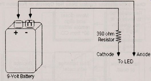
Fig. 9-9. Basic circuit for testing the segments of an LED or LCD the
test points, and be sure to include the current-limiting resistor
10.2 Batteries that are low or dead will obviously cause the controller to fail. Even batteries that have some kick left may cause some trouble, so even after testing them with a meter, try a fresh set.
10.3 While the batteries are out of the transmitter, inspect the battery contacts. They should be bright and shiny. If not, there may be insufficient current getting to the transmitter circuits, Clean the contacts and reinsert the batteries.
10.4 Most remote controllers for CD players work by emitting short pulses of infrared light. Sunlight striking against the player may over load the receiving sensor, so the commands from the transmitter are not adequately received. Always shade the sensor from direct sunlight. If the player is subjected to sunlight, the remote control function might not operate properly even after the light has been blocked. Wait five to 10 minutes for the sensor and surrounding components in the player to cool down.
10.5 dirty switch contacts in the remote control might cause all or some of the functions to fail, Open the remote and liberally spray the switches with an electrical contact cleaner. Inspect the wiring and solder joints and make repairs as necessary.
9.10.6 Broken wires and bad solder joints between the receiver sensor and the main PCB may also cause problems. Open the player only until after you are certain that the transmitter is operating properly (use the light sensor described in Section 5 to be absolutely sure). Inspect the wires and solder joints; test the continuity with a volt-ohm meter. With the test probes connected to either end of each wire, the reading should be 0 ohms. A reading of infinite ohms is an indication of an open circuit.
9.11. The player does everything it should, with one important exception; it’s quiet as a mouse.
With CD players at least, this is an undesirable circumstance. Unlike most other audio components, if you are plagued with no sound, the fault is almost always external to the compact disc player.
Remembering how a CD player works, the great majority of its internal electronics and mechanisms must function properly to even make the disc spin.
9.11.1 The disc is upside down in the player.
Although this usually causes the player to stop, an upside down disc can also prevent audio playback, and the player might function properly otherwise.
To the player, the label writing seems like a giant scratch. So much of the disc is affected, that even though tracking and focus can be minimally retained, the high number of errors trigger the muting circuits, and you don't hear anything. End of lecture; reinsert the disc the right way.
-------------
Chart 9.10
Remote Control Does Not Operate or Function Properly.
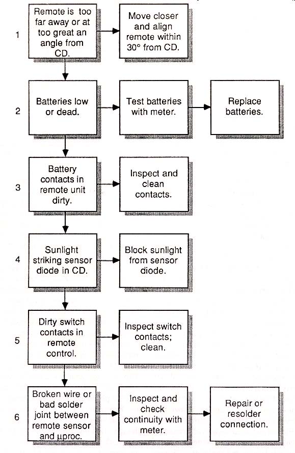
Remote is far away or at too great an angle from CD.
Batteries low or dead.
Battery contacts in remote unit dirty.
Sunlight striking sensor diode in CD dirty switch contacts in remote control.
Broken wire or bad solder pint between remote sensor and roc
Move closer and align remote within 30° from CD.
9 V.
Test batteries with meter.
Inspect and clean contacts.
Block sunlight from sensor diode.
Inspect switch contacts; clean.
Inspect and check continuity with meter
Replace batteries.
Repair or resolder connection.
----------
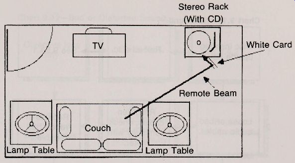
Fig. 9-10
9.11.2 Loose audio cables between the CD and the amplifier is a common cause of no sound.
Visually inspect the cables and test them using a meter. Replace or repair bad cables. If your CD has a headphone jack, connect a pair of headphones to it. You'll hear sound if the CD is operating properly.
9.11.5 Be sure the function switches on the amplifier are set correctly. Specifically, be sure that you’ve selected the CD player (push CD, AUX, TAPE, or other button as required) and that the mute switch is out.
9.11.4 Many amplifiers have two speaker switches-one for speaker pair "A" and another for speaker pair.
Make sure the "A" switch is down to route the sound to speaker pair 4'A." If there are no speakers connected to the ''B" speaker terminals in the rear of the amp, and the "B" switch is pushed in, the protection circuits in the amplifier may cut off the sound. This prevents a circuit over load.
If you still can't hear anything, inspect the speaker wires and make sure they are not broken.
If your amplifier has a headphone jack, connect a pair of phones to it. If you hear sound, you know that the audio from the CD is at least getting to the amplifier.
A number of compact disc players have a sound level adjustment. This control alt ers the level of audio signal to the amplifier. If the control is set too low, the player might not provide the am plif ier with a strong enough signal. Turn the control up and see if it has any effect. With some players, the headphone level knob also controls the output level to the amplifier.
9.11.6 The audio output wires in the player might be shorted out. This will not only prevent sound from reaching the amplifier, but you might also hear a low humming sound through the speakers. Immediately turn the player off and unplug it. Remove the cover and visually inspect in and around the audio output jacks for shorted wires or foreign metallic objects.
Use a meter to test the resistance of the jacks.
With the test leads connected to the inner and outer connectors of one jack, the resistance should measure between 10,000 and 50,000 ohms. Test the other output jack as well. A very low or zero reading is an indication that the output is shorted. If the cause cannot be found, the audio output circuit must be serviced. With some players, the circuit is on its own printed circuit board; in others, the audio output circuitry is contained on the main PCB.
9.12. The audio from a CD player is not sup posed to be distorted in the least, but several factors can contribute to bad sound. If there are repeated unconcealed errors in the audio output.
-----------------------
Chart 9.11 No Sound.
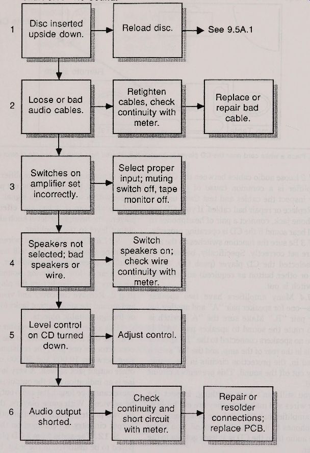
Disc inserted upside down.
bad Loose or audio cables switches on amplifier set incorrectly.
Speakers not selected; bad speakers or wire.
Level control on CD turned down.
Audio output shorted.
Reload disc.
Retighten cables, check continuity with meter.
Select proper input ; muting switch off, tape monitor off.
switch speakers on; check wire.
continuity with meter.
Adjust control.
Check continuity and short circuit with meter.
Replace or repair bad cable.
Repair or resolder connections; replace PCB.
---------------------
Chart 9.12
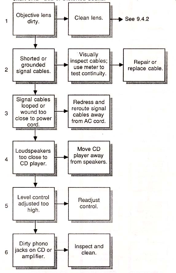
Bad or Distorted Sound.
Objective lens dirty.
Shorted or grounded signal cables.
Signal cables looped or wound too close to power cord.
Loudspeakers too close to CD player.
Level control adjusted too high.
dirty phono jacks on or am ler i
Clean lens.
Visually inspect cables;
use meter to. nt inuity. 1 test c 1 MS Redress and
ute signal i rer
cables away from AC cord, Move CD player away m speakers.
Readjust control.
Inspect and clean.
See 9.4.2
Repair or replace cable.
--------------------
Chart 9.13 Unconcealed Audio Errors During Playback.
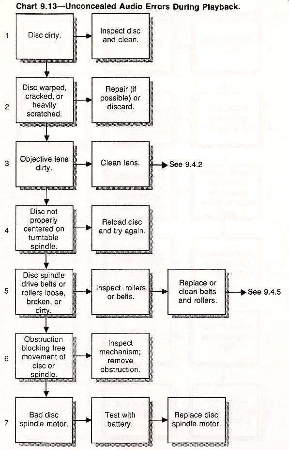
Disc dirty.
Disc warped, cracked, or heavily scratched.
Objective lens dirty.
Disc not properly centered on turntable indie s
Disc spindle drive belts or rollers loose, broken, or
Obstruction blocking free movement of disc or indle.s
Bad disc spindle motor.
Inspect disc and clean.
Repair (if possible) or discard.
SVAS Clean lens.
Reload disc and try again Inspect roller or belts.
Inspect mechanism; remove obstruction.
Test with battery.
See 9.4.2 Replace or clean belts and rollers.
Replace disc spindle motor.
----------------------
... refer to Chart 9.13. The troubleshooting chart you are now reading assumes that the disc is free of defects and that it has been loaded properly.
9.12.1 Loose, shorted, or grounded audio cables between the CD and the amplifier is a common cause of hum and distortion. Visually inspect the cables and test them using a meter. Replace or repair bad cables. If your CD has a headphone jack, connect a pair of headphones to it. The sound should be clear and undistorted.
9.12.2 Excessive hum can also be caused by poorly shielded signal cables, or cables routed closely to ac power cords. The hum is caused by the close proximity of the alternating current field.
If hum is a problem, examine the quality of the cables. The better the cable, the better the shielding, and the greater the rejection of ac-induced hum.
Route the cables as far from ac cords as possible, and keep the cable lengths as short as possible.
9.12.3 Components inside the CD player may be adversely affected if they are subjected to sonic vibrations from the loudspeaker. If your speakers are too close to the player, the vibrations may distort the digital and analog signals, and cause data errors and high frequency ringing. The best remedy is to move the CD or speakers so that there is at least six to eight feet of distance between them.
Separate them even further if you like to listen to your music at high volume.
9.12.4 A number of compact disc players have a sound level adjustment. This control alt ers the level of audio signal to the amplifier. If the control is set too high, the player may over load the input circuits of the amplifier. Distorted sound is the likely result. Turn the control down and see if it has any effect. With some players, the headphone level knob also controls the output level to the amplifier.
9.12.5 dirty phono jacks on the CD player or amplifier may impede the signal and cause noticeable audio distortion. Clean the jacks with an electronic contact cleaner. Inspect the cable connectors; clean them too if they look dirty.
9.13. Unconcealed audio errors are clicks and pops that you hear when listening to a disc. Skips and long periods of silence--where there should be none--are other forms of unconcealed errors. None should be present in a CD player that’s working properly and playing an undamaged disc.
9.13.1 About 98 percent of all the skips, clicks, and pops you'll hear are caused by a dirty disc. Before every use, wipe your discs with a soft cloth.
If a disc gets dirty, clean it with a recommended CD cleaner.
9.13.2 A disc that is warped, cracked, or heavily scratched might also exhibit extensive unconcealed audio errors--if the disc plays at all. Inspect the disc for damage. You can sometimes salvage a scratched or warped disc. See Section 5 for deails. Manufacturing defects can also cause heavy popping, clicking, and skipping. About the only se rious manufacturing defects you can see are air bub bles in the protective plastic and an off-centered stamping.
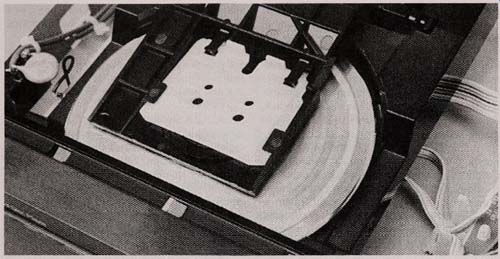
9.13.3 With some drawer loading players, the clamping flapper may not engage the disc against the drive spindle properly, and the disc may spin off center in the tray. A certain amount of eccenricity can be compensated for by the pickup and racking circuits, but a large amount of wobble ends up as unconcealed audio errors. Remove the disc and reinsert it.
If the problem persists, carefully inspect the disc. Look closely at the stamping encased inside the protective plastic. It should be exactly centered.
Sometimes, the stamping is centered in the plastic, but the hub is not in the exact center of the disc.
You can check for this by putting the disc in the machine and playing it. Look closely at the edge of the disc as it spins in the player, as depicted in Fig. 9-11. Direct a flashlight into the tray if necessary. Some slight wobble is normal, but an excessive amount is a good indication that the disc was improperly stamped.
9.13.4 Something may be blocking the free movement of the disc or spindle. You can usually hear the motor or disc scrape against the obstruction.
9.13.5 A bad spindle motor may spin, but not at the correct speed. Worn bearings may cause the motor shaft to wobble, again causing speed imperfections. You can isolate the problem to the spindie motor by disconnecting the drive and press the Play button. Check for any movement in the shaft that could indicate worn bearings. If the motor makes excessive noises while spinning, its a good indication that it is bad.
The motor will spin only for a few seconds, until the system microprocessor discovers something is amiss. The system processor won't activate the motor unless the interlock switches are closed. If you don't have a disc inserted in the tray, manually defeat the switches by attaching a jumper between the switch terminals.
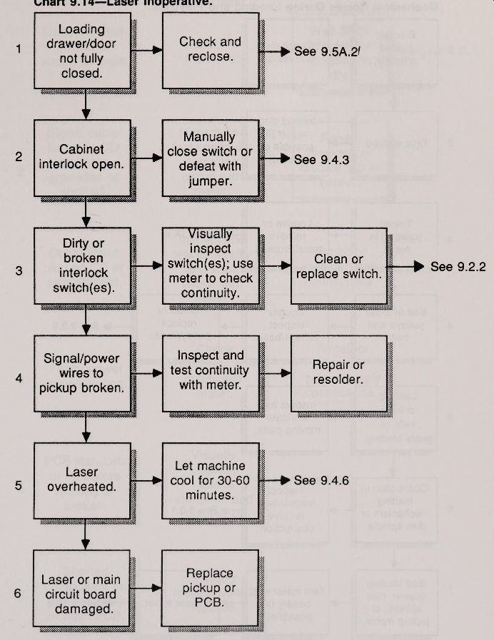
9.14. Some problems can be narrowed down to the laser diode--it doesn't emit light when it should. Since laser diodes have an average design life of over 5,000 hours, it’s unlikely that the laser will burn out in the average use of the player although it is a distinct possibility with a player that’s five or six years old.
There are many reasons why the laser diode may not emit light, and only a few of them have to do with the laser itself or the pickup mechanism.
You can test for laser light output by using the infrared light sensor described in Section 5.
9.14.1 Inspect the wires leading to the pickup mechanism. If any look broken, loose, or crimped,
----------Fig. 9-11. Carefully watch the disc as it spins for signs of
faulty manufacturing. Don't touch the disc while it is in motion.
------------
... the laser diode may not be getting the proper signals, or may not be receiving power. Test the continuity of the wires with a volt-ohm-meter. With the test probes connected to either end of each wire, the reading should be 0 ohms. A reading of infinite ohms means that there is probably a break some where in the wire, or that the solder joints are cold.
Replace the wires or resolder the connects as necessary.
9.14.2 The laser diode as well as the components on the PCB may be faulty. The laser may not be getting the signals from the system microprocessor to turn on, or the laser diode itself may be burned out. A failure in the laser diode means that the optical pickup must be replaced. This can be expensive and requires specialized tools. A faulty component on the main PCB generally involves replacing the entire board.
9.15. Mechanical noises are those terrible grinding, crunching, rattling, and squeaking noises that can emanate from the player. A well designed player is nearly silent in operation, and any noticeable noise is indicative of a malfunction inside the
9.15.1 A disc that’s off -centered on the spindle may wobble during playback. The sound you unit.
-------------Chart 9.14 Laser Inoperative.
------------
Chart 9.15 Player Makes Unusual Mechanical Noises During Loading and Playback.
------------------Chart 9.16
You Receive an Electric Shock When You Touch the Player.
------------------
... hear may be the bearings in the spindle groaning under the increased stress. Reinsert the disc and the problem should go away. If it does not, the disc clamping mechanism may need adjustment. Open the player and locate the flapper. This spring loaded mechanism clamps the disc in place after loading and during play. Look for loose or broken parts. Unlike the loading mechanism and optical pickup assemblies, the adjustment and repair of the flapper are non-critical, and does not generally require special tools.
9.15.2 Like an off-centered disc, a warped disc can cause the bearings in the spindle to groan. Remove the disc and inspect the disc for warpage.
Slight warpage can sometimes be cured by applying pressure to the disc (as described in Section 6). An unrepairable disc should be discarded.
9.15.3 A number of machines use plastic gears to drive the loading mechanism from the motor. A gear is mounted on the motor shaft, and meshes with a straight toothed rail. When the motor shaft turns, the gear inches the loading mechanism along the rail, thus opening the drawer or door. Inspect the gear and rail to be sure that none of the teeth are broken and that the gear teeth are meshing properly.
Even if the loading mechanism looks fine, the gears and rails may still bind against one another, and cause grinding sounds. If necessary, apply a small dab of grease on the gear surfaces or oil to shafts and levers.
9.16. The words "thrilling" and "breathtaking" are often used to describe the experience of listening to music on a compact disc. The word "shocking " should not be in the CD users vocabulary, unless there is something wrong with the player.
A CD that gives you a shock-even a mild one-should not be used. Some or all of the ac power has been shorted to the metal cabinet, so when you touch the player, you get a shock (and if the jolt is big enough, you get to do the "kilowatt dance," which looks a little like the jitterbug but can really put you in the hospital). Before playing another disc, unplug the machine, isolate the cause, and fix it.
You can test for ac leakage current with the following procedures.
The ac leakage current test determines if any part of the ac line has come in contact with the metal cabinet or base. It is a safety check to prevent a potential shock hazard. It requires the use of a volt-ohm meter.
With the CD player unplugged, short the two flat prongs on the end of the ac cord, as illustrated in Fig. 9-12. On the meter, select the kOhms function and a range of no less than 1,000 kOhms. Connect one test lead from the meter to the jumper on the ac cord. Connect the other test lead to any and all bare (not painted) metal parts of the player. For a typical CD player, the meter will read about 500 to 1,000 kOhms--if you get any reading at all.
A reading substantially lower than this is a good indication that the power supply has come into contact with the metal parts of the player. If this happens, inspect the power cord as it leads into the player, as well as the Power switch, the transformer (usually bolted onto the back of the machine), and the wires leading from the transformer to the printed circuit board. If the wires are broken, or are shorted to the cabinet, repair the fault before using the player.
Not all exposed metal parts of the CD will return a high value. Touching the center conduct or of one of the audio output connectors could yield a low resistance, of 40 or 50 kOhms. This is considered normal with some machines.
Water is a poor conduct or of electricity, but it’s good enough to short the ac power cord or the power supply terminals against the player cabinet.
Condensation can also form a light film of moisture that can conduct some current, and although the shock may be slight to the human body, it could damage the player electronics.
9.16.1 The signal cable between the CD player and amplifier may be shorted. Inspect the cable for obvious damage and test it with a volt-ohm meter.
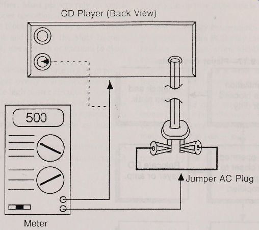
Fig. 9-12. Using a volt-ohm-meter to test for possible leakage current.
Connect the test leads across the center and middle conduct or of each cable. You should get a reading of infinite ohms. If you get any other reading, it is an indication that the cable is shorted.
9.16.2 Determining if the output of the CD is shorted is a little tougher. The resistance values can vary, but they should be within 10,000 to 50,000 ohms when the test leads are attached across the center and outer connectors of each output. A substantially lower reading, or a reading of 0 ohms, indicates a short.
9.16.3 The wiring leading to and from the power supply may be faulty. Inspect the ac cord leading to the power transformer and power switch.
Use your meter to check for short circuits. Examine the power transformer for obvious damage.
Check the solder terminals to make sure that none are touching the cabinet. Look closely because even one small strand of wire in the ac cord can cause at least a partial short circuit.
Examine the wiring from the transformer to the power supply circuitry. This is sometimes located on its own PCB, other times on the main PCB. Use your meter to check for obvious short circuits. At least one of the wires from the power transformer will act as the circuit ground for the player. You should receive a low reading when checking this wire. The other wires should yield reasonably high resistances.
9.16.4 The power supply and main PCBs are generally insulated from the cabinet and base using plastic standoffs. When secured with metal hardware, the boards are electrically isolated from the cabinet with plastic or rubber insulators. Inspect the mounting hardware to see if any part of the boards are touching the base or cabinet. Inspect the insulators and look for breaks and cracks. Replace any broken standoffs or insulators.
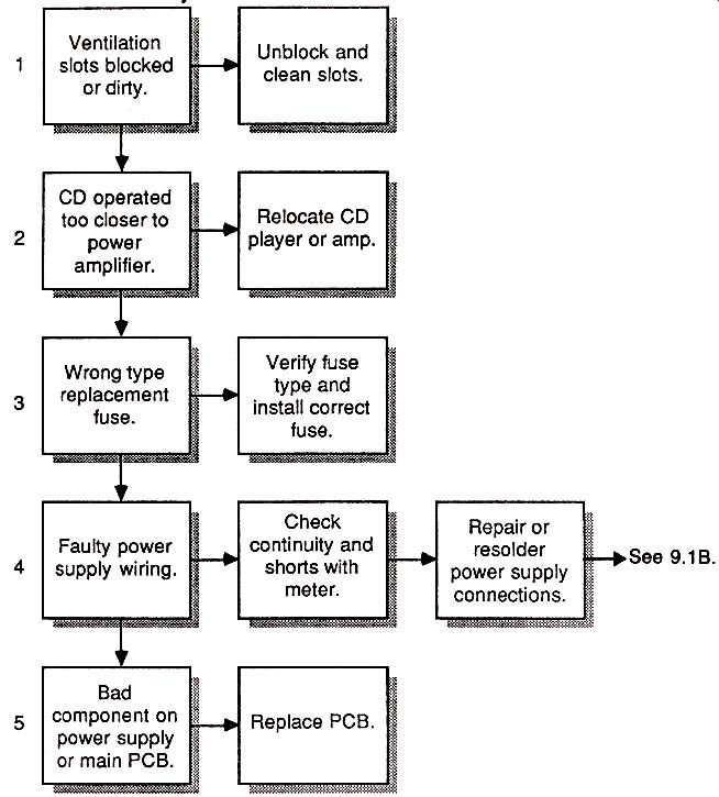
9.17. A player that gets abnormally hot is not only a potential fire hazard, but will exhibit erratic behavior. You can easily tell if the player is getting warmer than normal by touching its cabinet. It should not be noticeably hot to the touch. If it is, you should investigate the problem before playing any more discs. Continued use of the player might damage it beyond repair.
9.17.1 CD players don't consume much power,
---------------------
Chart 9.17
Player Overheats.
Ventilation slots blocked or dirty.
CD operated too closer to power amplifier.
Wrong type replacement fuse.
Faulty power supply wiring.
Bad V. nent on comp. power supply or main PCB.
Unblock and clean slots.
Relocate CD player or amp.
Verify fuse type and install correct fuse.
Check ntmuity and c shorts with meter.
Replace PCB.
Repair or resolder. power supply connections.
------------------
... so cooling is not as critical as it is with, say, a 100 watt power amplifier. Most players rely on ventilation slots for proper operation. It is important that these slots not be blocked, either by some outside object or by dust and dirt. If the slots become blocked with dust, use a brush or vacuum to clean them.
9.17.2 A CD operated too close to a large power amplifier might get overly warm because of the heat put out by the high power circuits in the amp.
For proper operation of your CD player, as well as the other components in your stereo System, you should keep your amplifier separate as much as possible.
9.17.3 Many CD players use external or internal fuses. If a fuse blows, it is important to replace with the same value of fuse as the original. This is particularly true if the fuse is the current-limiting type.
9.17.4 Faulty components on the power supply board or main PCB may cause excessive overheating. You can often identify the responsible component by carefully touching each one. To test, power the player for a while until the heat rises, hen turn it off. Unplug it from the wall socket.
Lightly touch each component. Except for the voltage regulators none should be hot to the touch (some ICs may be quite warm, but they should not burn your fingers). The voltage regulators, usually mounted on the power supply board, can get hot but are usually kept within a safe operating temperature by the use of aluminum heat sinks.
= = = =