AMAZON multi-meters discounts AMAZON oscilloscope discounts
9. Custom-Built Chips and Gate Arrays
At the present writing about 25 percent of industry output is in custom-de signed chips. Such a chip is usually incorporated in a single product or a family of closely related products. Custom-built chips are expected to reach 50 percent of IC volume by the 1990s. This means that a whole system can be put on a single chip. That has already occurred with a telephone exchange (PBX) where a chip replaced four circuit boards full of components.
=====
NOTES:
1. CROSSHATCHING IDENTIFIES CONTACT AREA.
2. TOLERANCES FOR ALL RESISTORS SHALL BE WITHIN ±3 PERCENT OF ABSOLUTE VALUE AS LISTED IN TABLE AT LEFT. THE RESISTANCE RATIO OF R17:R18, R20:R21, R24:R25 AND R26:R27 SHALL BE WITHIN ±1 PERCENT.
3. EDGES OF THE SUBSTRATE SHALL BE WITHIN 0.020 IN. WIDE BORDER AS OUTLINED BY PHANTOM LINES IN FIG. B.
4. LASER SCRIBED SNAPTRATES ARE USED. THE SCRIBE LINE SHALL LIE WHOLLY WITHIN THE 0.020 IN. WIDE BORDER AS OUTLINED IN FIG. B.
5. HOLES ARE SHOWN FOR REFERENCES ONLY AND ARE NOT TO BE SHOWN ON PHOTOMASKS.
====
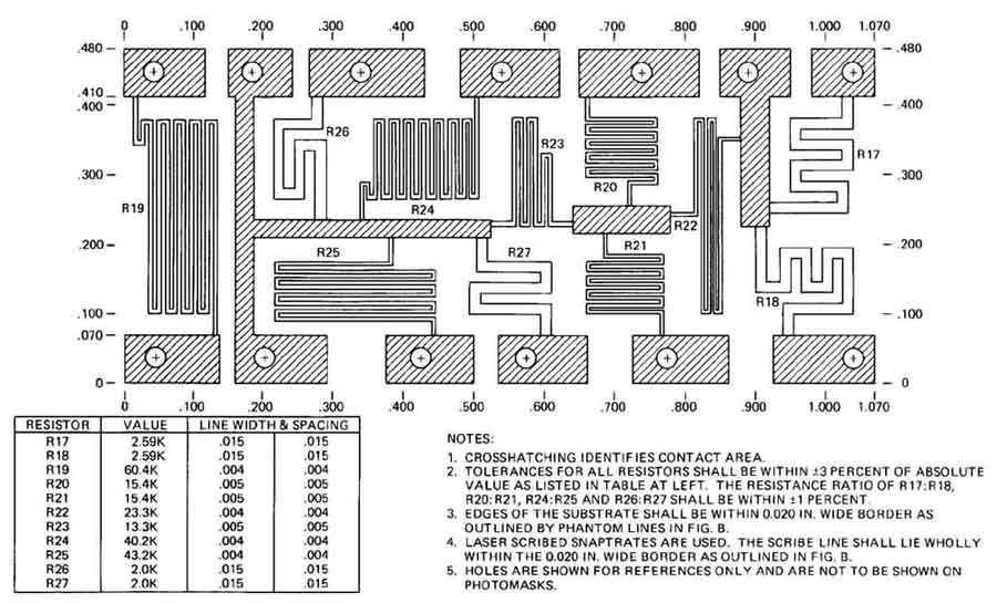
FIG. 23 Working drawing for a thin-film circuit. The photograph is
shown in FIG. 20.
FIG. 24 A hybrid laser preamplifier circuit. This is a combination of thick- and thin-film technologies and some chips. An IC chip is at the center, and a chip capacitor is at the right edge, halfway up. (Texas Instruments, Inc.)
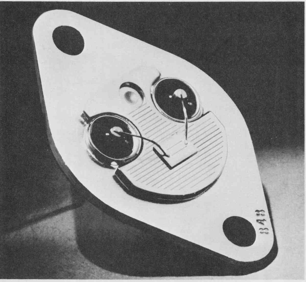
FIG. 25 A power MOSFET having vertical integration of different manufacturing
technologies. (Motorola Semiconductor Products, Inc.)
Already available in large numbers and in many forms of circuits are gate arrays. These are standardized grids of transistors that are connected together in the last processing step. They are mass-produced in the manufacturing plant up to the final step or two. Then the gates or transistors are put together to suit the requirements of a customer. Three of many gate array circuits are shown in schematic form in FIG. 27.
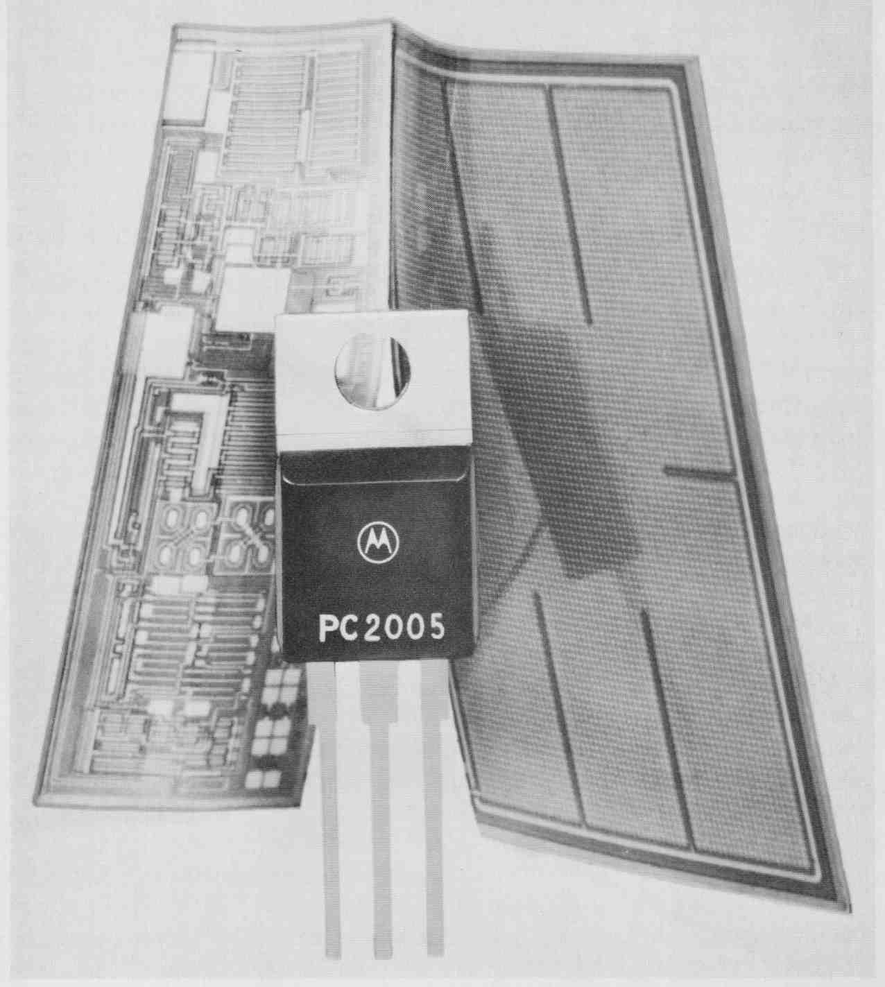
FIG. 26 Another “smart” power transistor in which high-speed CMOS logic
and high-current TMOS vertical power structuring are on a single chip.
(Courtesy of Motorola Semiconductor Products, Inc.)
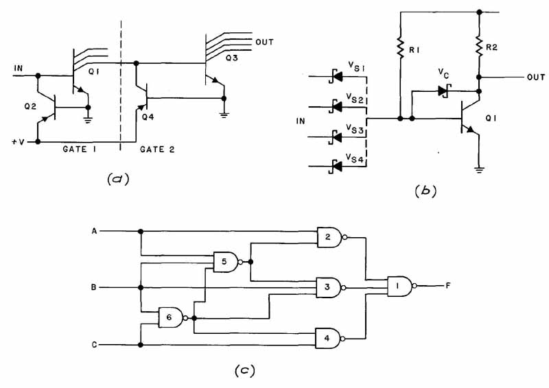
FIG. 27 Gate arrays: (a) multi-output single-input inverter; (b) circuit
switching SDL network; (c) multi-input NAND network. (Texas Instruments,
Inc.)
Another approach that is under heavy development at several large companies is called wafer-scale integration. Instead of cutting a large wafer into many chips, why not use the whole area for a single superchip? That is what one organization is doing: developing a 2.5 sq-in. chip that will replace approximately 100 conventional chips. The result is tremendous speed, but also terrific heat; the latter requires a solution not yet forthcoming.
10. Microprocessors and Microcomputers
The development and maturity of LSI technology made possible the design and quantity production of microprocessors. A microprocessor provides on one chip the CPU, or central processing function, of a digital computer. (See the glossary in this Section for microprocessor terms.) One microprocessor chip might do the work of 80 standard integrated circuits. A refinement of the microprocessor has resulted in the development of a chip called a microcomputer, which has most of the functions of a digital computer. Actually the two terms are rather loosely applied, and there will probably be some confusion about these titles for years to come. The term microcomputer is sometimes applied to personal computers, partly to distinguish them from minicomputers, which are larger.
The famous 8080 microprocessor has an arithmetic logic unit (ALU), accumulator, registers (three types), and control logic and can address up to 512 input-output ports. Memory is minimal. The TMS 9900 microprocessor has an ALU, three registers, control logic, ROM, and input-output (I/O) control lines. It is usually augmented with other chips, including RAM. The 8748 micro computer has a CPU, a clock circuit that times and coordinates data flow, ROM and RAM, I/O circuits, and expansion circuitry which enables the user to extend the capabilities of the chip. As powerful as this chip is, it is usually mounted on a board with still other components ( FIG. 30).
In FIG. 28 we have two photographs of the Motorola MC 68000 micro processor, which is 246 X 281 mils in size. It is the brain of the Apple Macintosh personal computer. It is a 16-bit microprocessor with 32-bit registers, a 32-bit program counter, and a 16-bit status register. It is also one of a family of processors, some of which are:
- MC 68010 Virtual memory processor
- MC 68450 Direct memory access controller
- MC 68652 Communications controller
- MC 68881 Floating-point coprocessor
- MC 68020 Enhanced 6800 microprocessor
These microprocessors greatly extend the performance and capabilities of the 68000 family. The microprocessor is also used in the IBM 370 XP computer and in the Apollo engineering workstations, as well as some other workstation applications.
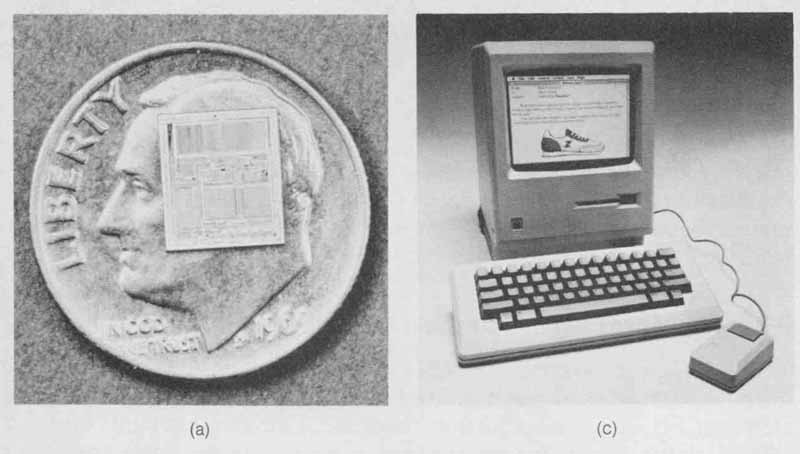
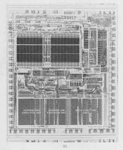
FIG. 28 The Motorola MC 68000 microprocessor: (a) the .24 X .28 in
chip (lying on a dime); (b) an enlarged photograph of the chip; (C) the
Apple Macintosh utilizing the 68000 microprocessor. Shown are the main
unit, detachable keyboard, and mouse pointing device. (Motorola
Semiconductor Products, Inc. and Apple Computer, Inc.)
A functional diagram of an older microprocessor is shown in FIG. 29. It is very common to find combinations of microprocessors or microcomputer chips and other devices mounted on a PC board. These single-board computers can perform many simultaneous or sequential operations for computation or for process control. FIG. 30 is the photograph of such a board. Such arrangements provide essentially the same functions as a minicomputer. This is a low-cost (hundreds of dollars) way to control many parts of a system or process, and to provide convenient monitoring (video tube, LED), input (teletype, sensors), and ease of programming (FORTRAN and BASIC languages and floating decimal point). A functional flow diagram of the SBC 80/10 is shown in Fig. 6. This diagram is explained in Sec. 6, which also gives an overview of how a microprocessor works by means of a general flow diagram.
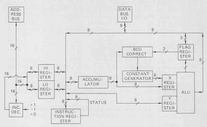
FIG. 29 Functional diagram of the 8080A microprocessor: 8- and 16-bit
ad dress busses allow direct addressing of 64 kilobytes of memory. Numbers
indicate the number of data bits of the various busses. The block at
the lower left represents the incrementer-decrementer unit. (Intel Corporation.)
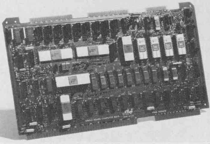
FIG. 30 The SBC 80/10 single-board microcomputer. It contains an 8080
cpu, 1 kilobyte of RAM, 4 kilobytes of EPROM, and 48 programmable I/O
lines. (Intel Corporation.)
Microprocessor Glossary
CPU: Central processing unit, the heart of a microcomputer. It contains the arithmetic logic unit, control circuitry, and registers for the temporary storage of data.
ALU: Arithmetic logic unit, that part of the chip that performs all the arithmetic using binary techniques. Most ALUs perform boolean logic operations and have shift capabilities.
Input-Output (I/O) Circuits: These are “ports” to keyboards, printers, cathode-ray-tube, sensors in industrial and automotive control systems, and other possible devices.
Register: A temporary storage unit. Program counters and instruction registers have dedicated uses. Accumulators have more general purposes.
RAM: Random-access memory, a volatile memory requiring electric power to retain data. Data can be stored for manipulation by other parts of the processor or computer.
ROM: Read-only memory, a nonvolatile memory in which data are stored permanently; no electric power is required to retain the data.
PROM: Programmable read-only memory.
EPROM or UV EPROM: Erasable programmable read-only memory, in which data can be erased by ultraviolet (UV) light.
EEPROM: Electrically erasable programmable read-only memory.
Bits and Bytes: A bit is a binary digit, a 0 or a 1. A byte is an 8-bit “word” or unit. A kilobyte represents 1000 bytes or 8000 bits. Microprocessors that handle 8-bit words (bytes) are suitable for tasks such as educational, automotive, or home control systems. Devices that handle 16-bit words are designed for even more sophisticated systems, such as navigation or data processing. Microprocessors that handle 32-bit words are in newer, faster computers and systems.
11. Applications of Microprocessors
It is impossible to give the reader a comprehensive idea of the many present and future uses of microprocessors. Rather, we can present only a few examples in this and the next two Sections. From a control standpoint these low-cost microcircuits are making switches, gears, levers, springs, and relays obsolete in many applications.
Automotive control is one area that readers will appreciate. The Delco Remy Misar system includes four inputs: crankshaft position, coolant tempera ture, reference timing, and manifold vacuum. Basically, this system “looks up” the optimum spark advance in a memory map that corresponds to the driving conditions and passes this information to the distributor. FIG. 31 shows this system in diagrammatic form. Another approach puts both spark advance and exhaust gas recirculation under the control of a microprocessor. Table 3 shows the computer command control system for a six-cylinder engine of the 1980s.
Other applications are in the area of industrial controls. One such arrangement checks the dimensions of sheet-metal parts, reads a binary digital signal determining whether each part is within the allowable tolerance or not, and provides whatever statistical analysis is required. Another, incorporated in a cash register, drives a seven-segment digital readout, prints a receipt with the amount of the purchase on it, and makes change — all at practically the same instant.
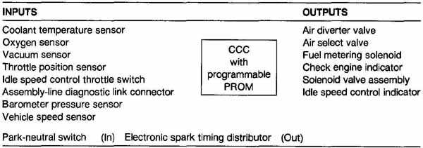
TABLE 3 Emissions Control System [ Command Control (CCC)]
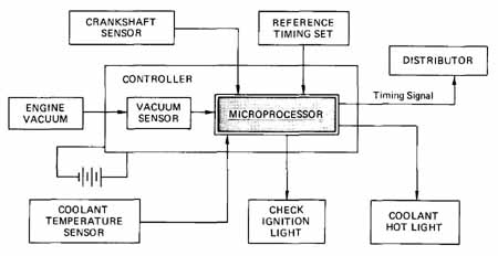
FIG. 31 Flow diagram of a spark-advance system in a car. (Reprinted
from Electronics, September 29, 1977; Copyright © 1977 by McGraw-Hill,
Inc.)
Programming a microprocessor system may require quite a bit of effort. In fact, because of the low cost of these circuits, the programming may cost more than the initial cost of the hardware. Program writing is often done in machine language or mnemonic (assembly) language. To use either, the user must develop an understanding of the language and how the processor works and skill in using the language and processor. Typical instructions might be:
INSTRUCTION DESCRIPTION
INXB Add 1 to BC register pair
JNC Jump if C flag is false
DCXB Subtract 1 from BC register pair
OUT Output data from accumulator
STA Store A value at direct address
Here is how the HERO I robot by Heathkit is programmed to say
“HELLO”:
INSTRUCTION DESCRIPTION
The robot, which has a Motorola 6808 microprocessor, utilizes a two-digit, or digit-letter, code for each of 64 different sounds (phonemes). These can be put together to make words and sentences.
These are a few of more than a hundred such instructions for a particular microprocessor system. By spending more money for hardware or software, it is often possible for a user to have a system that utilizes a language that is easier to learn and work with, such as FORTRAN and BASIC. In BASIC, for example, 2 times 3 is simply written or typed 2*3. PRINT 2*3 produces the answer, 6, on a typewritten sheet or video screen.
Personal computers represent a logical development in the use of micro processors. Because of their low cost, compactness, and versatility, they are well suited for use around the home. They have been used to control lighting and sound throughout a house, for video-type games, to plan menus for those on a diet, to lock the front door at night, to keep track of investments, to keep telephone numbers and Christmas card lists up to date.
Personal and professional (desk-top-size) computers are also used for word and data processing. With special commercially written programs, usually on floppy diskettes (disks), they permit the user to type material, then see it on a monitor, then correct mistakes, rearrange material, etc., and finally have it printed exactly as desired. Also, using the coordinates of the computer screen, the user can make drawings appear on the monitor. If desired, these can be printed on a plotter or dot-matrix computer. The following program in BASIC language will draw a ground symbol on an IBM PC screen:
INSTRUCTION DESCRIPTION OF LINE
90 LINE (480,115) to (480,119) Short vertical line at top of symbol
100 LINE (467,119) to (493,119) Topmost and longest horizontal line
110 LINE (471,122) to (489,122) Middle horizontal line
120 LINE (475,125) to (485,125) Lowest and shortest horizontal line
The screen on which this symbol was drawn has 640 elements from left to right and 200 from top to bottom. Unfortunately, these must be divided by the dimensions of the “tube,” viz.: (640/12) = 53 points to the inch and (200/10) = 20 points to the inch. This must be kept in mind when writing the program. The ground symbol was drawn in the right part of the screen as part of a series (menu) of symbols. The top of the symbol is at horizontal coordinate 480 and vertical coordinate 119. (Zero is at the top.) Other equipment makes drawing less complicated. The mouse and the joystick (toggle) are examples. The Cascade system developed for McGraw-Hill is another example. It includes extensive software.
12. Chip Wars and the Learning Curve
As the reader has learned from reading this Section and elsewhere in the guide, a battle is continuing between U.S. chipmaking companies and their Japanese counterparts. Although the IC industry was begun in the United States, the Japanese are a strong No. 2 and are winning many customers in the United States. By the end of 1979, the Japanese had won 42 percent of the U.S. market in what was then the latest generation of memory, the 16K RAM. They did better in 1980 with the 64K RAM, and they may be doing it with the 256K, which is the generation that follows the 64K RAM. The same sort of economic warfare prevails with consumer products that use these and other semiconductor devices.
The good news is that the user benefits, because as the density (the number of functions) on the chip increases, the cost per function decreases. This has been possible because production costs fall as volume increases, workers gain experience, and the proper investment in new plant and automated equipment is made. The result is known as “learning curve pricing.” The basic concept is that whenever the total number of products doubles, the unit price reduces by a constant percentage. The density of ICs was 50 transistors in the 1960s and will be as many as 20 million transistor functions in the 1 990s.
FIG. 32 is a learning curve graph with four curves that apply at various times and places in the electronics industry. The 70 percent ratio curve has been drawn through two points, one at 1 OM and $1 and one at 20M and $0.70, and then extended in a straight line across the logarithmic paper. It is the steepest of the curves and will provide the best improvement. In fact, it has an improvement rate or ratio of …
log 0.70 —
_____ = =—0.515
log2 0.301
…which is negative but is generally used in a positive sense since it represents an improvement in costs. Tables have been constructed to provide unit costs or times and cumulative costs or times. Table 4 shows excerpts from two tables. It is used as follows: If 10 hours were required to produce the first unit with an 80 percent learning curve, production of the 10th unit would require 0.4765 X 10 or 4.765 hours (using the upper part of the table). According to the values given in the lower part of Table 4, if it cost $10 to produce the first unit at 75 percent, production of 10 units would require 5.589 X 10 or $55.89. (The numbers in the table may be considered to be hours or dollars.)
Using the graph in FIG. 32, we see that with the 70 percent learning curve, increase in production from 100 million units to 500 million would reduce the cost from $0.31 to a little less than $0.14. Since the graph is not very accurate, we can go to Table 4 and find comparable numbers, 0.3058 and 0.1336 in the upper part.’ It is highly probable that any particular unit will not cost $1 each for 1OM production as the graph is drawn. This means that one would have to apply a factor, or ratio, after obtaining the numbers from the graph or table.
It should be stressed that the learning curve applies only when large volume is assured. Within a large company there may be several different learning rates for different products. In general, the same learning curve applies to a “family” of units. This might mean a microprocessor and its related chips or a family of surface-mounted resistors.
= 0.4368 0.4368 X 0.31 = $13.54
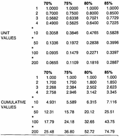
TABLE 4 Learning Curve Tables
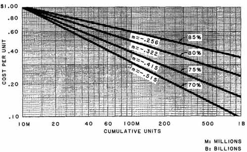
FIG. 32 The learning curve graph with four curves and their improvement
rates (m values).
SUMMARY
The development of integrated-circuit manufacturing has changed the face and substance of the electrical and electronics industry as well as the lives of millions of users of these products in the United States and throughout the world. The diffused silicon process— and later metal-oxide technology— made possible medium-scale integration (100 to 1000 transistor functions), large-scale integration (more than 1000 functions), and VLSI (100,000 or more).
Manufacture of some circuits, namely, thin-film and thick-film, is more analogous to the printing process than to the diffusion process. They also provide more accurate values of such passive devices as resistors. Accuracy of manufacture requires extremely high precision in drawings for integrated circuits, with the result that most are generated by the computer. These drawings are usually executed many times the size of the circuit they help produce.
Such consumer products as digital watches, pocket calculators, microprocessors, and microcomputers have been made possible because of LSI technology. Microprocessors are usually employed in dedicated situations, whereas microcomputers can be programmed for different uses. Industrial applications will be presented in the next Section.
A major trend is toward the combination of technologies to produce hybrid circuits. Thin film and thick film have been combined with silicon-chip technology to great advantage. Custom and semicustom silicon chip technology is gaining in market penetration. The learning curve applies to much of microelectronics manufacturing.
QUESTIONS
1. What are the advantages of thin-film circuits over integrated silicon circuits?
2. How much thicker is a typical thick-film resistor than a thin-film resistor?
3. What drawings would be required for the manufacture of a thin-film circuit? What else would probably be included in the drawings?
4. What are three specific problems brought on by the manufacture of great numbers of components?
5. Why is CMOS technology so popular in the production of silicon chips?
6. Why is computer-aided drafting used for drawings of ICs?
7. What are two functions of the photolithographic process?
8. What are some typical widths of thin-film resistors?
9. How is it possible to obtain a series of several circuits from one integrated semiconductor pattern that has capacitors, diodes, resistors, and transistors?
10. What are five drawings, of a series, required for production of a completed integrated- (semiconductor-) circuit package?
11. What is your concept of hybridization insofar as this Section is concerned?
12. What trends do you identify in electrical drawing for miniature circuits and devices in the next decade?
13. What is the difference between a RAM and a ROM? Between a PROM and an EPROM?
14. List five functions in a large office that might be controlled by a micro computer or microprocessor.
15. When does the learning curve concept not apply in electronics manufacturing?
PROBLEMS
1. Layouts of three masks for a multiemitter transistor are shown in Fig. 33. The upper right corner of the collector diffusion mask is shown. The collector is a U-shaped area that comes down each side and stops even with lines a and b. The scales around the edges have marks that are - in. apart (on the final drawing). Horizontal distances at c are in. Make a drawing of all the masks, including the collector of this IC transistor on 11 X 17 or 12 X 18 paper.
2. Metal-oxide semiconductor technology is somewhat different than the bipolar method for IC manufacture. The following steps are employed: (1) the initial slice is N-type oxidized silicon; (2) the first photoresist process cuts a window in the oxide; (3) the surface in the window is re-oxidized (thin layer); (4) windows for the source and drain are cut by the second photoresist process; (5) boron is diffused “in” to form the source and drain; (6) the oxide in the main window is stripped off (7) pure oxide is formed for the gate region; (8) windows for the source and drain are cut by the third photoresist process; and (9) aluminum contacts are deposited and then defined by the fourth photoresist. Make a flow diagram of a MOSFET fabrication process similar to that shown in FIG. 4.
3. FIG. 34 shows the schematic diagram of a thin-film resistor and a scale drawing that is complete except for the resistors. It is desired to fabricate resistors 0.02 in. (0.51 mm) wide. Compute the length of the resistors using the equation L = [ — 120)1401W.
Make a table for the resistors, including value in ohms, width, and length for each. Make a scale drawing of the complete thin-film layout using these widths and lengths. A suggested scale is 1 in. = 0.20 in. Including the 0.2 grid system as shown should enable you to make a reasonably accurate scale drawing. Use 8 X 11 paper for the layout only, 11 X 17 paper for layout, table, and schematic.
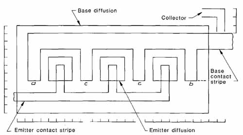
FIG. 33 (Prob. 1.) Partial mask layout for an IC transistor.
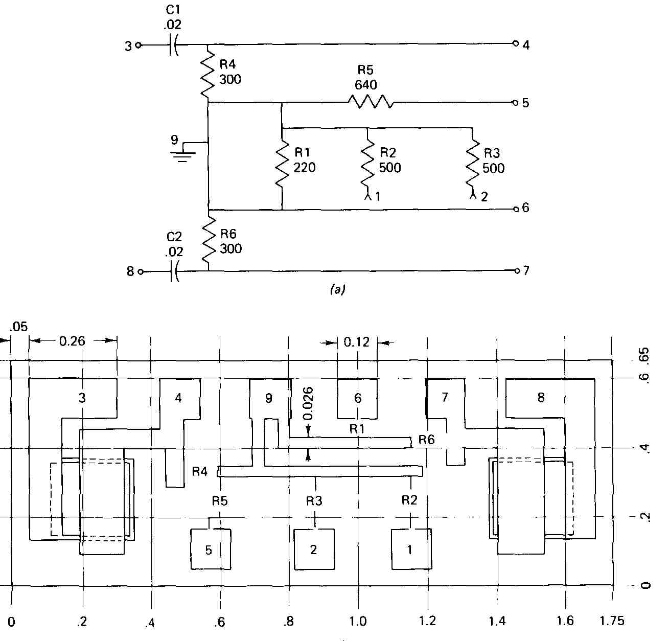
FIG. 34 (Prob. 3.) Thin-film graphics: (a) complete schematic diagram;
(b) scale drawing, incomplete. (Original scale was 1 in. = 0.20 units
or 5:1.)
4. The integrated-circuit bar diagram shown in FIG. 35 can be connected to form an incline dc amplifier, circuit shown in the last section (Fig. 4b). Draw the mask that would be required for metallization that would produce the amplifier circuit. Your instructor may require you to draw the complete IC also. Suggested scale: 1 in. = 10 units (mils), shown around the edges. Let the conductor paths be 1.5 units wide. The capacitors have the same value. Use any shape for resistors, except that R and R should have same shape (8.5 X 11).
5. FIG. 36 is a perspective drawing of the architecture of a microprocessor chip. (a is the CPU; b, the clock circuit; c, memory circuitry; d, expansion circuitry; and e, I/O ports.) Rough outside dimensions are 4.5 X 5.6 units. Some other rough dimensions are (a) 1.4 X 2, (c) 1.4 X 1.3, and (d) 3 X 0.5. Estimate any other dimensions you need and make an isometric drawing of this chip. Add the letters and leaders much as they appear in the figure, and then write a legend in the lower part of your drawing describing the five parts (a through e).
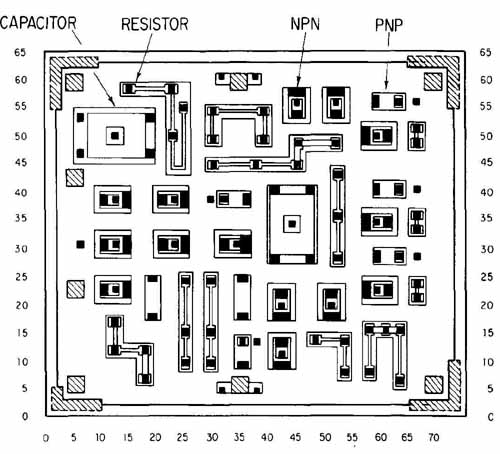
FIG. 35 (Prob. 4.) Bar diagram of a bipolar SSI. Typical devices
have been labeled. Units around the edge are mils.
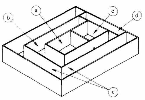
FIG. 36 (Prob. 5.) A perspective drawing of the “architecture” of
a microprocessor chip: (a) CPU; (b) clock circuit and other auxiliary
circuits; (C) memory; (d) expansion circuitry; (e) I/O ports.
6. FIG. 37 includes the incomplete flow diagram of a cash register system. Make a flow diagram of the completed diagram in which item 1 is the 8085 CPU, 2 is the 8155 RAM-I/O-timer, item 3 a receipt ticket printer, item 4 an 8355 RAM, and item 5 a change dispenser. (Use 8 X 11 paper.)
7. The flow diagram of a typical microcomputer is presented in FIG. 38. Draw the flow diagram with the following additions: At (1) add the Keyboard Display block with flows to Keyboard Switches & Sensors and the Alpha-Numeric Display blocks as shown in the upper part of the figure. At (2) add the Standard Interface block with flows to PROMS, etc., as shown in the upper part of the drawing. Add light shading to the CPU and data bus. (Size: 11 X 17.)
8. FIG. 39 shows a rudimentary drawing of the dual-displacement engine. Sensors measure temperature, transmission gear, throttle position, and engine load and speed. At a certain condition the control module shuts down three of the cylinders. Draw the outline-schematic drawing of this system, showing the engine, sensors, microcomputer, control signals, and connecting lines. (Use 8 X 11 paper.)
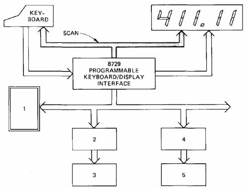
FIG. 37 (Prob. 6.) Incomplete diagram of a microprocessor-based cash
register. Shaded busline is for internal scanning. The other busses are
for control and data transmission.
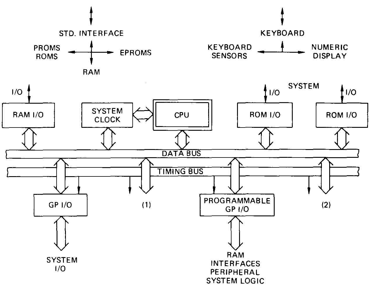
FIG. 38 (Prob. 7.) Block diagram of a typical microcomputer. Additional
blocks are to be added at 1 and 2.
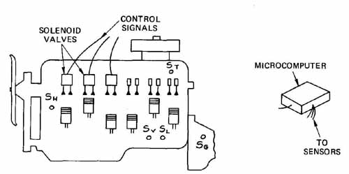
FIG. 39 (Prob. 8.) Rudimentary outline of a six-cylinder dual-displacement
motor and pictorial view of a microcomputer. Approximate sensor locations
are shown as follows: SH, temperature; S engine speed; SL, load; S gear;
and ST, throttle.
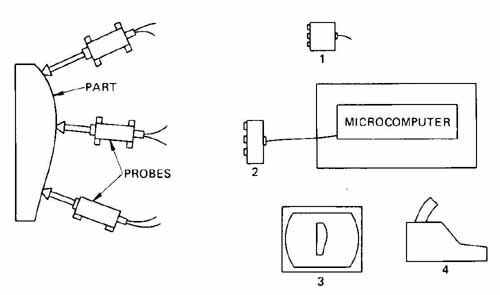
FIG. 40 (Prob. 9.) A gaging system for manufactured parts. (A single-board
microcomputer is used.)
9. FIG. 40 shows a gaging system which is used to determine whether or not a part is within acceptable tolerance. Item 1 is a junction box for a line leading from each probe. Item 2 is a manifold which also has a line from each probe. The manifold and junction box each feed into an 80/20 microcomputer board. The board has outputs to video display (3) and printer (4). Show a schematic flow diagram of this complete system. (Use 8.5 X 11 paper.)
10. How many minutes would be required to provide just the 50th trans ponder if 2.3 h were required to produce the first one at (a) 75 percent learning rate and (b) at an 85 percent learning rate?
11. If it cost $6.90 to assemble the first transceiver unit, what would it cost to assemble the 100th unit at (a) an 80 percent learning curve rate and (b) an 85 percent rate?
12. If it takes 69 minutes to manufacture the first smart power transistor, how many more minutes would be required to make the first 10 units at an 85 percent rate than it would at the 80 percent rate?
13. In order to arrive at a competitive price for a new surface-mounted device, the manufacturer estimates it would cost $1.75 per unit if 10 million were to be made. If a 75 percent learning curve could be followed, how much would it cost per unit if sales (and production) could be increased to 60 million?