AMAZON multi-meters discounts AMAZON oscilloscope discounts
A record-player is one of the simplest electronic systems. The system diagram, in its basic form, has only three components--the pick-up, the amplifier, and the speaker. The system has been illustrated in Figure 10.1. But audio frequency amplifiers, i.e. amplifiers designed to amplify signals at around the frequencies to which the human ear is sensitive, have their own special problems, and the circuits are designed to solve these problems. The range of frequencies to be amplified is well within the capability of even simple circuits. The generally accepted 'hi-fi' frequency range is between 20Hz and 20kHz, though only young children can hear frequencies as high as this, and at frequencies as low as 20 Hz the sound is more felt than heard. The first requirement for an audio amplifier to be considered here is the power output. A typical transistor radio or portable tape-player will provide an output power of around 500mW into a small speaker. This sort of power level proves quite adequate for general listening at fairly close range. But for hi-fi, where the faithful reproduction of high energy transient sounds is important, 20 W is considered a sensible minimum.
Let us return to the portable player. To deliver about 500 mW into the speaker requires about 55 mA from a 9 V supply, if we neglect any inefficiencies in the system. This power output will be required only rarely the loudest sounds, with the volume turned well up. This appears to be well within the capabilities of a handful of small dry batteries. A very simple way of driving a speaker is shown in Fig. 1. (The speaker itself is dealt with in detail ). You will (I hope) recall from Section 10 that in order to amplify audio signals in an undistorted way, the output of an amplifier has to be able to swing positive and negative of a neutral point.
This is achieved in amplifiers like the one in Fig. 1 by biasing the transistor so that the collector is at approximately half the supply voltage.
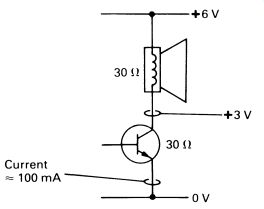
FIG. 1 a simple way of driving a speaker with a transistor amplifier
In the simple amplifier in Fig. 1, this happens when the resistance across the transistor's emitter-collector junction is equal to the resistance of the collector load; the transistor and the load resistor are then the two halves of a potential divider with equal resistance either side, and the mid point will be at half the supply voltage.
The speaker's coil has a resistance of 30 ohm, so the total resistance is about 60 ohm. These figures are quite realistic. Thus the current taken by this output stage is roughly 6 x 1000/60 = 100mA. For small and medium sized dry batteries, this represents a fairly short life. And notice that the current is consumed even when there is no output from the speaker. In fact, the current taken from the supply will, on average, always be the same, since for the most part audio signals will reduce and then increase the transistor's emitter-collector resistance symmetrically.
There is also the question of what happens to the power lost from the batteries. Half is dissipated by the transistor, and the other half by the speaker--300mW each. Thus cooling, even in a modest amplifier, is some thing that needs to be taken into consideration.
And finally there is that 100 mA flowing continuously through the speaker, pulling the speaker cone out of its true central position. It means that a small speaker could not be used, and for this (and other) considerations, the whole amplifier is going to be quite large.
In case this design seems so hopelessly unsuitable, a complete amplifier based on the simple circuit above is shown in Fig. 2. This was produced commercially in the 1960s, and actually makes a good, musical sound. It would be quite an interesting project to make it, as the transistors (or their equivalents-the circuit is pretty tolerant) are still available.
The transistor will need a heat sink of some sort (a piece of aluminum 1 mm thick by 100 mm square would do) and a speaker of at least 150 mm diameter is recommended. Speakers with 30 ohm coils could be hard to find, so the circuit values have been changed for a 15 ohm speaker. The circuit takes about 300mA from a 6 V battery (a 6 V motorcycle battery would have a reasonable life!). Use a crystal cartridge, they were widespread in the 1960s and have a high output. This amplifier hasn't a great deal of gain.
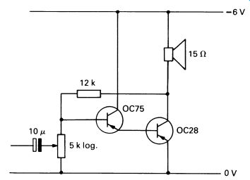
FIG. 2 a practical direct-coupled class A audio amplifier
The system of volume control is simple, the control working as a potential divider to feed a proportion of the signal to the amplifier, according to the setting. The use of a logarithmic-law control is standard, and gives a smooth increase and decrease in volume. If you make this amplifier as a demonstration, try the effect of a linear-law potentiometer.
The amplifier we have been discussing is known as a class A audio amplifier. A properly designed class A amplifier can have very low distortion, but will always waste a great deal of power.
1. CLASS B AMPLIFIERS
Today, with a few eccentric exceptions, audio amplifiers are class B amplifiers. It is possible (but more difficult) to obtain very low distortion, and the class B amplifier consumes power that is much nearer to being proportional to the output power at any instant. In other words, a loud signal will cause the amplifier to draw a heavy current from the supply, whereas when quiescent (no signal) it will take very little current.
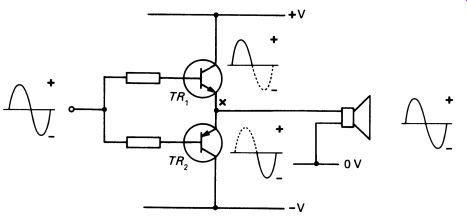
Fig. 3 illustrates one of the basic forms of the class B amplifier.
This is known as a complementary-symmetry class B amplifier because it is a symmetrical circuit, and because it uses complementary transistors, a pnp and an npn type, as the output devices. The circuit depends for its operation on the fact that the transistors require different polarity of signal to drive them. The input waveform is shown in the diagram-–one cycle of a sinewave at an audio frequency. The first part of the signal, the positive half-cycle, makes TR 1 conduct and act as an amplifier. TR2 , on the other hand, will be turned off (non-conducting) by the signal. This means that point 'X' on the diagram, the output to the speaker, is the output of the transistor amplifier TR 1. The speaker's speech coil is the emitter load of this amplifier.
FIG. 3 a class 8 audio amplifier in which the output current is
shared between two transistors
The second-negative-half-cycle of the input signal switches TR 1 off, but makes TR 2 conduct. This time TR 2 is the amplifier, with the speaker still the emitter load of this amplifier. The result is that the two halves of the input signal are handled by two different transistors, but the output from both amplifiers is fed to the speaker, to reconstitute the original signal. The efficiency of the amplifier comes from the fact that, with no input signal, neither transistor is conducting, so no power is taken from the supply, and no energy needs to be dissipated by any part of the circuit (or the speaker) when there is no sound coming out of the amplifier.
Like most things, it turns out that the real circuit isn't as simple as basic theory seems to suggest. The load lines in Figure 8.12 suggest the nature of the problem: the fact that the transistors do not respond to a signal in a linear manner when operated near cut-off point. The transistors have to be biased so that they are just conducting enough to move them into the linear part of the characteristic. Distortion will then be minimized.
In class B amplifiers it is distortion at the point where one transistor takes over from the other that is most often encountered, especially in cheap or poorly adjusted designs. Such distortion is called crossover distortion. An example of crossover distortion in a poorly adjusted design is shown in Fig. 4. The input is a sinewave, in this test.
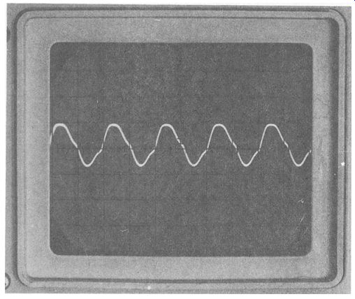
FIG. 4 crossover distortion
A circuit with a suitable bias system to maintain the transistors at the correct point on the curve is illustrated in Fig. 5. The diodes have a secondary purpose, that of providing the amplifier with thermal stabilization. For the lowest possible crossover distortion, the operating points of the transistors need to be set accurately. As the amplifier operates, particularly if it is delivering a large output, the transistors will get hot, changing the characteristic curves and necessitating a slightly different bias setting.
Automatic compensation is obtained by putting the diodes in contact with the transistors, so that the increase in temperature of the transistor also heats the diode. The diode's conduction changes correspondingly, altering the bias conditions so as to compensate (approximately) for the transistor's changes. The system is surprisingly effective. Notice that the amplifier in Fig. 5 uses a split supply, like the op-amps. This is an efficient mode of working, but the use of a split supply may well be inconvenient in a small portable device. It is possible to use a single supply, but a capacitor must be put in series with the speaker to prevent a direct current flowing all the time. The layout is shown in Fig. 6. Because of the large currents flowing, the capacitor must be very large, in the order of hundreds of microfarads. Often it will be by far the largest physical component in the circuit.
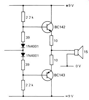
FIG. 5 a practical class 8 output stage to drive a 15 n speaker;
the diodes are in contact with the encapsulations of the transistors
and provide thermal compensation
In the design of the class B output stage we have concentrated on power-handling and efficiency. Gain is a low priority, and the amplifier will invariably use more, low-power stages to amplify the incoming signal to a level where it can drive the output transistors. (In the next section of this section we will consider preamplifiers, as they are called.) Before leaving the subject of class B power output stages, it is important to realize that the design shown in Fig. 5 is by no means the only one possible. It is often used because it is simple and works well. However, amplifiers are still in use-paradoxically in cheap radios-that have transformer coupling of the input and output stages, and identical transistors on both sides of the 'push-pull' class B layout. The transformer coupling to the input is used to provide the two halves of the system with input signals of opposite phase. An output transformer may be used to match the speaker impedance to the output stage more closely. A transformer coupled design is shown in Fig. 7.
Transformer coupling is now used rarely, since the price of transformers and their size make them undesirable for modern circuits. The transformer also adversely affects the frequency response and distortion, so transformer coupling is not used in hi-fi designs.
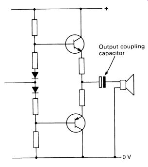
FIG. 6 the requirement for a split power supply can be obviated
by the use of an output-coupling capacitor.
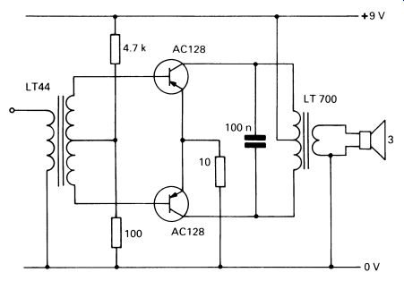
FIG. 7 a typical transformer-coupled class B amplifier.
2. PREAMPLIFIER AND DRIVER STAGES
Often the class B output stage is preceded by a single transistor amplifier that provides some of the gain needed for the amplifier. This in turn is preceded by a preamplifier, which provides most of the gain and may also incorporate tone and volume controls. Any division between the driver and preamplifier is rather artificial, and today the whole system coming before the power amplifier tends to be termed the 'preamplifier'. A simple preamplifier can be made with the ubiquitous op-amp. Neglecting tone and volume controls for the moment, the design in Fig. 8 is completely practical.
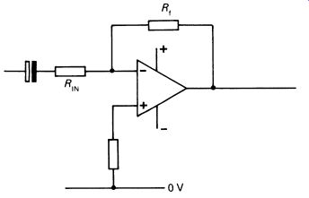
FIG. 8 an op-amp preamplifier stage.
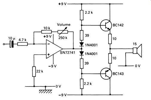
FIG. 9 a practical audio amplifier, using the op-amp as a preamplifier
and a class 8 output stage; the volume control operates by varying the
gain of the preamplifier.
Compare this circuit with the one in Figure 12.6a; this is a simple inverting amplifier. Capacitor coupling to the power stage is not in fact needed, so the complete preamplifier and power amplifier system is arranged as shown in Fig. 9. This is in fact an entirely practical circuit, and is an amplifier with a quite respectable performance. The frequency response should be only about 3 dB down at 20 Hz and 25 kHz, it has an input impedance of 10 kOhm, and will deliver about 200 mW into a IS .n speaker.
Note that the diodes should be in contact with the cases of the transistors for automatic thermal compensation. The volume-control system is unusual in that it is in the feedback line and works by altering the overall gain of the preamplifier. A more usual system would be to use a potentiometer to proportion the incoming signal, like the one shown in Fig. 2. However, the feedback system reduces the amplifier's background noise as the volume is lowered, a desirable characteristic. In hi-fi amplifiers it is usual to design the preamplifier with discrete components. It is possible to build preamplifiers with exceedingly low distortion-verging on the unmeasurable.
3. TONE CONTROLS
The very simplest kind of tone control, used in the very cheapest designs, uses a simple 'treble-cut' circuit. A variable resistor in series with a capacitor is placed across the signal line at a convenient point. When the control is set to low resistance, the capacitor, working as a frequency-sensitive resistive component, shorts out a substantial proportion of the high frequency signal. The variable resistor gradually reduces the effect of the capacitor as it is turned up towards maximum resistance. This type of circuit, shown in Fig. 10, is widely used, though it has little to recommend it apart from cheapness.
The design used in almost every hi-fi amplifier, and most other medium and high-quality applications, is the Baxandall tone-control circuit, named after its inventor. The Baxandall circuit works by selective feedback, and has the advantage that, with comparatively few components, it is possible to control bass and treble separately, and to give cut and lift to each as required. A Baxandall tone control circuit using an op-amp is shown in Fig. 11.
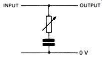
FIG. 10 a cheap and nasty form of tone control
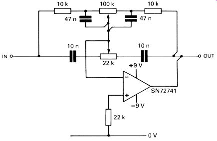
FIG. 11 a Baxandall tone-control circuit, used in all quality audio
equipment; this circuit provides both lift and cut at bass and treble
frequencies
This amplifier has a gain of unity (i.e. with the tone controls 'flat', the output signal is at the same level as the input signal) and, when used in an amplifier system, would be placed between the preamplifier and power amplifier stages.
4. INTEGRATED CIRCUIT AMPLIFIERS
The trend in electronics today is towards fewer and fewer components in a given system. Fig. 12 shows a typical 200 mW amplifier of the late 1960s, with twenty individual components. The circuit is straightforward and quite comprehensible, and you should have no problem in following it. Compare it with Fig. 9, which has fifteen components and a substantially better performance. The main saving is by using the op-amp.
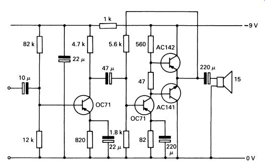
FIG. 12 a typical low-power amplifier of the late 1960s; it involves
twenty individual components and about forty soldered joints.
An audio amplifier is just the sort of device that is suitable for production as an integrated circuit there is a large market for identical units, and all components in the system (most of them, anyway) can be produced using microelectronic techniques. It is not surprising, therefore, that there is no justification nowadays for building an audio amplifier from discrete components, unless it is for hi-fi applications.
An example of just what can be done in integrated circuit audio amplifiers is the LM380, a 2-watt audio amplifier. Including the volume control, the complete amplifier uses six components. The full circuit is shown in Fig. 13.
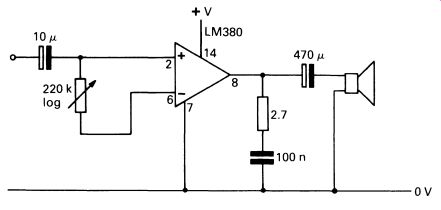
FIG. 13 a modern integrated circuit audio amplifier; there are only
six components and about twenty soldered joints.
The LM380 has obvious affinities with the op-amp; there are two inputs, inverting and non-inverting, but the output stage is class B. It will deliver 2 W maximum into an 8 ohm speaker when connected to a 20 V supply, but will work with any supply voltage down to a few volts, giving proportion ally less output. It also incorporates various safety circuits-it will shut down if it overheats, and the output can be shorted to either supply rail without damage. There is an outwardly similar high-power version, the LM384, that delivers 5 W peak from a 22 V supply.
Fig. 14 shows the pin connections-the circuit is in the familiar 14-pin DIL pack. The middle six pins are connected to the 0 V supply line, but also provide a heat-sink path for the output transistors. If the printed circuit board is designed with a large area of copper, say 20 em 2 , connected to these pins, then heat is conducted away from the output transistors and is dissipated by the copper of the printed board itself-a neat design idea.
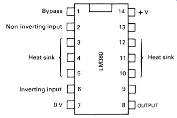
FIG. 14 pin connections of the LM380 audio amplifier circuit; the
center three pins on each side are connected to the output transistors
and provide a heat-sink path : Bypass ; +V ; Non-inverting input ; Inverting
input 0v OUTPUT
There is a companion IC for the LM380 and LM384, the LM381, which contains most of the components for a stereo preamplifier system.
There are, of course, many different integrated circuit audio amplifiers from many different manufacturers. Power outputs vary from 500mW to several tens of watts. Heat-dissipation arrangements range from fins built into the device to tags such as are used on power transistors. There is little point in cataloguing them here, except to indicate that the trend is away from complex amplifiers and towards ever simpler systems.
A general exception to this rule is hi-fi systems!
5. HIGH-FIDELITY AUDIO
There is not even a generally accepted definition of 'hi-fi'. All the standards so far produced have rapidly been thought of as far too low, while in fact the very best equipment now available is probably better than it needs to be. That is to say, the tiny amounts of distortion and 'unfaithful' reproduction are almost certainly far too small for even the most trained human ear to detect. This doesn't stop reviewers of hi-fi equipment thinking they can perceive such differences! Because integrated circuit audio systems are made for a specific price range, hi-fi amplifiers generally use discrete components in their construction, or at least use op-amps as the 'gain' element in rather complicated designs. The design of hi-fi equipment is very specialized, and well beyond the range of this guide, but it is instructive to look at the specification of a good hi-fi amplifier.
Power
The output power should probably be 20 W or more, not because this is a sensible level to use all the time, but because the amplifier is required to reproduce high-energy transient sounds without distortion. Also, modern speakers tend to be inefficient, trading small size and sound quality for electrical efficiency; they require lots of power to drive them to high volumes. Since hi-fi systems are invariably stereo (see below), this would be 20 W per channel, a total output power of 40 W. Manufacturers some times quote 'peak power', which is the amount of power an amplifier will deliver for a short period. Peak power is about twice the normal (r.m.s.) power.
Distortion
There are various measures of distortion. The most commonly used is total harmonic distortion (t.h.d.). A top-quality amplifier would achieve better than 0.01 percent t.h.d. across the entire audio range.
Frequency response
In the days of valve amplifiers and in the early days of transistor amplifiers it was quite difficult to arrive at a design which successfully amplified signals across the entire audio spectrum. It is not a problem today, and any good amplifier will handle signals from 20Hz to 20kHz: 'handle' needs definition in this context-the amplifier has to respond to, say, a 20Hz signal in the same way as to a 2kHz signal. Frequency limits are generally quoted to '3 dB down', meaning that the signal inside the quoted limits is no more than 3 dB smaller at the limits than in the middle. This is shown graphically in Fig. 15.
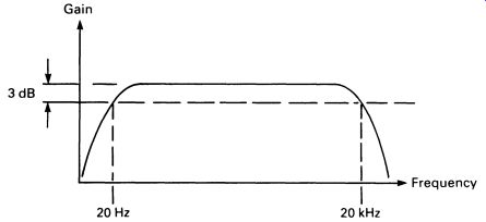
FIG. 15 an amplifier frequency-response curve (frequency response
is normally quoted at -3 dB limits).
Gain 20Hz-20kHz
It is not a good idea to have an audio amplifier that amplifies signals to too high a frequency, for ultrasonic frequencies can use up power and heat the output stage to no audible result. Most audio amplifiers are designed so that the frequency response dips dramatically above 20kHz. In the same way, very low frequencies are not wanted-playing the warps in a record will exercise the speaker cones, but will not contribute to the sound, and may actually detract from it.
Noise
Every amplifier produces some background noise, in the form of a steady 'hiss'. The noise is inherent in the way transistors work and can never be entirely eliminated. However, it is possible to reduce the noise level to a practically inaudible -70 dB, i.e. 70 dB (more than 3000 times) lower than the signal level. Hum, generally at mains frequency, and if not due to problems in interconnections between units, is always due to poor/cheap design. A hi-fi amplifier should have no discernible hum, even with the volume turned fully up.
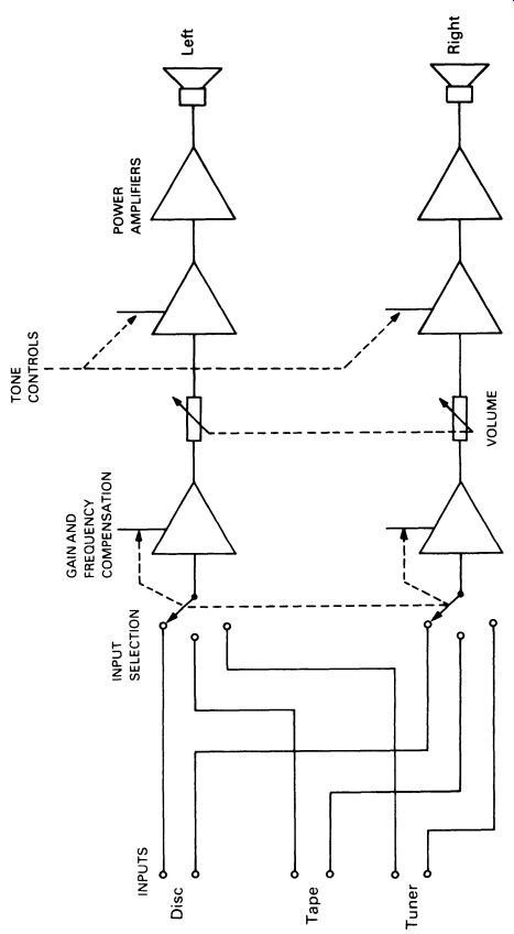
FIG. 16 system diagram for a stereo amplifier
6. STEREO SYSTEMS
The human hearing system is capable of locating objects in space by the relative volume of sound received by each ear. Thus a speaker placed on each side of the listener will be able to duplicate an entire 'sound stage' between the speakers, by presenting the left and right ears with different sounds. This is the principle of stereo sound, and is universal for hi-fi. It does require two of everything-two speakers driven by two amplifiers, with sound recorded in two separate channels. A system diagram of a stereo record-player is shown in Fig. 16. The relative loudness of the two channels (balance) is controlled by a 'two-gang' (i.e. two on one shaft) potentiometer, and tone controls are also ganged.
Although there is only one pick-up tracking the groove in the record, there are two completely separate channels of information recorded and replayed. Fig. I 7 shows a stylus resting in a groove of a stereo record. The groove is V-shaped, and the two side walls are impressed with separate vibrations for the left and right channels. The stylus is moved as shown in A and B by the two walls.
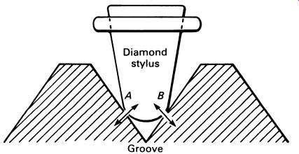
FIG. 17 separate information modulated into the groove of a stereo
record; the pick-up cartridge is sensitive to movement in both directions,
and movement in plane A or plane 8 will give separate outputs
Since the directions of movement are at right angles, the cartridge can mechanically separate the signals and generate separate outputs for the left and right channels of the system. Most modern cartridges are of the magnetic (moving-magnet) type, in which the movements of the stylus caused by the record groove are made to move a tiny permanent magnet mounted inside a fine coil of wire. The voltage induced in the coil constitutes the output, at most a few millivolts. There are, of course, two sets of coils, responding to the two channels-although cartridge designs differ from make to make, the principle is the same.
Crystal cartridges and ceramic cartridges are used on cheaper record players, and rely on the piezoelectric effect. The motion of the stylus bends a crystal of Rochelle salt, which has the property of generating an electrical voltage across its width when flexed. The voltage is quite high, up to 1 V, but the non-linearity of the output leads to a 'low-fi' output.
Ceramic materials can be made that give better linearity but lower output, about 100m V being typical.
Fig. 18 illustrates the general layout of a magnetic pick-up cart ridge. If the stylus is moved in the direction of the arrows, corresponding to one channel of the stereo recording, the magnet moves between the upper-left and lower-right pole pieces, inducing a small current in the coils.
This is the signal current that is amplified by the record-player. Since the magnet remains centered between the other two pole pieces, no signal is induced in these coils, or at least what small signal there is will be can celled out.
----------------
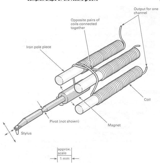
FIG. 18 internal construction of a moving magnet pick-up cartridge;
the moving parts-stylus, lever and magnet-have been shaded for clarity;
a pivot, usually of compliant plastic material, holds the moving parts
in place while allowing the stylus to track the complex shape of the
record groove
-------------------- The situation is reversed when the stylus moves in the other direction; in practice the stylus moves simultaneously in both directions to reproduce the two stereo channels.
7. COMPACT DISC DIGITAL AUDIO
The basic principle of sound recording on discs has been unchanged since Thomas Alva Edison invented it towards the end of the nineteenth century.
Sound is converted to mechanical vibrations that are used to cut an undulating groove in a suitable material when recording the sound. When replaying, the groove moves a stylus, which converts the mechanical movement back into sound. Huge improvements have been made since Edison's day, but overall, the principle is the same.
1982 (not as bad a year as it might have been, George!) brought the first major departure from Edison's system, if you exclude tape recording.
This was the 'compact disc' digital audio system, CD for short. This combines the advantages that the records have over tapes - random access of tracks, speed of mass reproduction, ease of storage -with superlative sound quality. The compact disc system uses digital recording techniques that guarantee near-perfect audio quality. Because of this, the compact disc system is described in the third part of this Guide to Mastering Electronics, Section 18.1.
QUESTIONS
1. What is the main disadvantage of class A amplifiers?
2. Class B amplifiers often feature internal temperature-compensating circuits. What are these for?
3. Why are integrated-circuit audio amplifiers preferred in most audio equipment, televisions, etc.?
4. What is the maximum power that could be delivered into an 8 n speaker by an amplifier operating from a 20 V power supply?
5. Hi-fi amplifiers are designed so that they will not amplify frequencies substantially higher or lower than the range of frequencies to which the human ear is sensitive. Why?