Suppose a computer was being fed information (digital words) from a number of different sources. The sources might be manually operated teletypewriters, transducers that are monitoring a chemical process, an electronic counter measuring the frequency of an oscillator circuit, etc. The computer can deal with these various inputs one at a time only. Thus, there must ye a way to select each input and exclude all others. The process is called data selection and in manual systems would probably be performed by a selector switch. The data appears first from one source and then from another. Since the information is entering into the computer in a more or less continuous stream of data, the process is also called multiplexing. The opposite problem, that of sorting a stream of digital words and routing each to its correct destination, is called demultiplexing.
DATA SELECTORS
Fig. 4-1 shows a 16-channel data selector/multiplexer, type 54150/74150. Its circuit operation is similar to the previously discussed one-out-of-four decoder. To select the data appearing at input E0, for example, we address the circuit with the data select input, A=B=C=D= 0. To allow the data to appear at output W, an enable signal also has to be provided at the input marked Strobe. The control circuit ( Strobe) has an inverted-buffer input and a logical 0 is needed for enabling.
With S = 0, and A=B=C=D= 0, Gate 0 will follow E0; if E0 = 1, Gate 0 = 1. Gate W has all inputs 0 except for the input ...
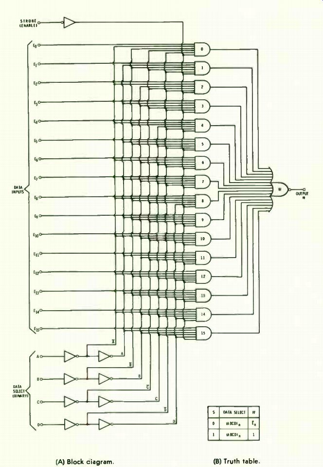
(A) Block diagram (B) Truth table.
Fig. 4-1. Sixteen-channel data selector/multiplexer.
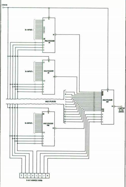
Fig. 4-2. Using multiple devices to increase input capability.
... from Gate 0. Therefore, Gate W will follow Gate 0, going to a 1 if Gate 0 is a 0 and going to 0 when it is 1. Thus, Gate W presents the negative of E.. Other outputs are selected similarly.
Circuit operation is summarized by the truth table, where (ABCD), is the address for any specific input E.
MULTIPLE DATA INPUT
What if the signal appearing at E is not just a single bit, but is a digital word consisting of 8, 16 or more bits How is this handled? One can see that, as long as S is 0, any data changes occurring at a selected input will be immediately transferred to the output. If the system is designed to function this way, no problem arises. In many cases, however, the Strobe signal will be a pulse train, with the enabling signals arriving in step (maybe slightly ahead or behind but always in the same relationship) with the data signals. In this case, the output W would go to 1 whenever S is 1. If the system is designed this way, the Strobe signal will probably be used as an enabling signal in the circuit being fed by output W. Thus, the Strobe signal controls both the data selection and data input to the following section.
The circuit shown in Fig. 4-1 applies directly to circuit type 54150/74150. Circuit type 54151/74151 is similar but has only 8 inputs for data and 3 inputs for address; thus, it can only multiplex 8 sources. The type 54151/74151 has an extra inverted output to give W; this output is labeled Y. Another 8-input, 3-address multiplexer, but without the Strobe circuit or the Y output, is circuit type 54152/74152.
MULTIPLE LOAD INPUT
Sometimes it is necessary to multiplex more than 16 signals.
This can be accomplished by using a tier or tree of devices as shown in Fig. 4-2, where 17 devices are used to select one input signal out of 256. Note that to address this circuit properly, an address word of 8 bits is needed; 4 bits are used to address device 17, and the other 4 bits are used to address devices 1 through 16.
Prev: Link | --Link | --DECODERS
Next: SHIFT REGISTERS
Guide Index : Transistor-Transistor Logic (early 1970s)