Fig. 7-1 . Checking the accuracy of a calibrated time base.
| Home | Audio mag. | Stereo Review mag. | High Fidelity mag. | AE/AA mag. |
7-1. To Check the Accuracy of a Calibrated Time Base
Equipment: Good-quality audio oscillator and lab-type am generator.
Connections Required: Connect the output from the audio oscillator or from the signal generator to the vertical-input channel of the scope.
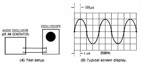
Procedure: Set the audio oscillator (or am generator) to various low, medium, and high frequencies; observe the amounts of horizontal deflection occupied by one cycle of the displayed waveform at various settings of the time/cm control.
Evaluation of Results: The period of the displayed waveform normally is equal to 1 / f, where f is the applied test frequency.
For example, in Fig. 7-1 the test frequency is 2500 Hz; the corresponding period is 400 p.s. In turn, if the time/cm control is set for 100 u.s/cm, the displayed waveform will normally occupy four horizontal divisions of the screen.
7-2. To Check the Accuracy of a Calibrated Vertical Attenuator
Equipment: Audio oscillator and audio voltmeter.
Connections Required: Connect output from audio oscillator to vertical input terminals of scope and to input terminals of the audio voltmeter. Test signal may be attenuated by 100-to-1...
(A) Test setup.
(B) Typical screen display.
Fig. 7-1 . Checking the accuracy of a calibrated time base.
(B) 100-to-1 pad to obtain low-level (A) Test setup.
... test voltages.
Fig. 7-2. Checking the accuracy of a calibrated vertical attenuator.
.... resistive pad, if required to obtain a suitably low-level signal (see Fig. 7-2).
Procedure: Check each step of the vertical-input attenuator and compare the peak-to-peak voltage indicated on the scope screen with the reading of the audio voltmeter. (Audio voltmeter may indicate in rms values, or both rms and peak-to-peak values; the peak-to-peak value is equal to 2.83 times the rms value.)
Evaluation of Results: The peak-to-peak voltages indicated on the scope screen should agree within reasonable tolerance with the peak-to-peak voltages indicated by the audio voltmeter. Note that the scope is likely to have an internal calibrating voltage; if so, this provides a useful cross-check.
7-3. To Check the Vertical and Horizontal Amplifiers for Linearity
Equipment: Audio oscillator.
Connections Required: Apply output from audio oscillator to vertical and horizontal input channels of scope as shown in Fig. 7-3.
Procedure: Adjust horizontal and vertical gain controls for a pattern that extends to the edges of the screen. However, do not exceed the linearity limits.
(A) Test setup. (B) Normal display.
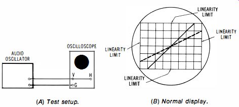
Fig. 7-3. Checking the vertical and horizontal amplifiers for linearity.
Evaluation of Results: Diagonal lines are displayed on the screen; the slope of a displayed line depends upon the relative vertical and horizontal gain settings. In any case, a line that is within the linearity limits of the screen should be precisely straight. If curvature is present, it is indicated that the vertical amplifier, the horizontal amplifier, or both, is/ are non-linear. The relative amount of curvature changes as the gain control settings are varied.
7-4. To Check the Phase Accuracy of a Dual-Trace Oscilloscope
Equipment: An am signal generator.
Connections Required: Connect output from generator to both the A and the B vertical-input channels, as shown in Fig. 7-4.
Procedure: Vary the test frequency up to the rated high-frequency limit of the scope, and observe the dual-trace pattern.
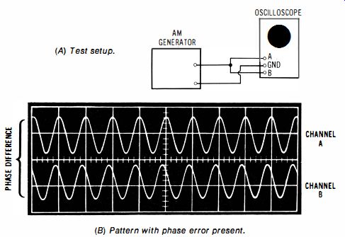
Fig. 7-4. Checking a dual-trace scope for A/B phase shift.
(A) Test setup. (B) Pattern with phase error present.
Evaluation of Results: The two patterns are normally precisely in phase with each other. If a phase error is present, it will become more evident at high frequencies. In such a case, the phase error may be noted and taken into account.
7-5. To Check a Vertical Amplifier for Overload Recovery
Equipment: An am generator and pulse generator.
Connections Required: Connect outputs from generators to vertical-input terminals of scope, as shown in Fig. 7-5.
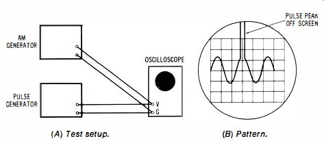
Fig. 7-5. Checking the overload recovery capability of an oscilloscope. (A)
Test setup. (B) Pattern.
Procedure: Synchronize the pulse generator from the signal generator, or carefully adjust the am generator frequency to make the sine wave "stand still" on the screen. Operate the am generator at a higher frequency than the pulse generator.
Display the sine-wave pattern ; then advance the pulse-generator output until the pulse component is off-screen vertically.
Evaluation of Results: The sine-wave pattern should not become distorted as the pulse component is increased into the overload region of the vertical amplifier. Note, however, that some lab-type scopes are designed for better overload recovery than others. When the overload recovery capability is good, a waveform may be expanded vertically as much as may be desired.
7-6. To Check a Differential-Input Scope for Common-Mode Rejection
Equipment: Square-wave generator.
Connections Required: Connect output from generator to one of the differential-input terminals and ground. Then, connect output from generator to both of the differential-input terminals and ground (Fig. 7-6).
(A) Test setup. (B) Pattern.
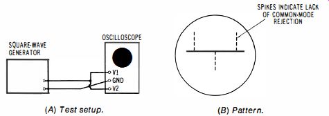
Fig. 7-6. Checking a differential-input scope for common-mode rejection.
Procedure: With the square-wave signal driving one of the differential vertical-input terminals, adjust the corresponding vertical attenuator for full-screen deflection. Then, set the other vertical attenuator to the same level. Apply the squarewave signal to both of the differential vertical-input terminals, and observe the screen pattern (if any). Evaluation of Results: Only a straight horizontal line will be displayed if common-mode rejection is complete. In practice, small irregularities may appear along the horizontal trace.
If tall spikes appear in the pattern, common-mode rejection is faulty.
7-7. To Check the Response of an Oscilloscope to Line-Voltage Fluctuation
Equipment: Variac or equivalent, and audio oscillator.
Connections Required: Connect power cord of oscilloscope in series with the Variac; connect output from audio oscillator to vertical-input channel of scope.
Procedure: Display the audio sine-wave pattern on the scope screen. Vary the output voltage from the Variac over the rated power-line voltage range for the scope. Observe pattern changes (if any) while varying the line voltage slowly, and while varying it rapidly.
Evaluation of Results: Virtually no change in pattern size, brightness, or stability will occur in a scope that has complete voltage-regulation circuitry. On the other hand, an economy-type design may be susceptible to pattern jumping and/or displacement, loss of sync, change in pattern size, and change in pattern brightness as the line voltage is varied.
7-8. To Determine Whether an Oscilloscope Radiates RF Energy
Equipment: An am radio receiver, signal generator.
Connections Required: Connect output from signal generator to vertical-input channel of scope.
Procedure: Place radio receiver in vicinity of scope. Apply a 1 MHz signal to the scope, and display the waveform on high-speed sweep, such as 0.04 u.s/ cm.
Evaluation of Results: Tune the radio receiver to a station in the midband reg ion, and vary the generator frequency. If the scope is radiating rf energy, a heterodyne squeal will be heard from the speaker. If the receiver is tuned through the am broadcast band, a rasping type of interference may be found at one or more regions of the band. Some scopes have a comparatively high level of rf radiation, and the condition cannot be classified as a fault. In such a case, the operator should keep the radiation field in mind when making tests on nearby high-impedance high-frequency circuitry.
7-9. To Determine Whether an Oscilloscope Case Is "Hot"
Equipment: An ac voltmeter and 100K resistor.
Connections Required: Connect ground terminal of scope to cold-water pipe vi a the 100K resistor. Connect ac voltmeter across the resistor.
Procedure: Turn scope "on" and observe meter reading (if any).
Evaluation of Results: The meter should read virtually zero, when the power switch of the scope is "off" or "on." A substantial voltage reading indicates that there is excessive power-line voltage gaining access to the scope case.
7-10. To Check the Immunity of an Oscilloscope to External Fields
Equipment: Radio transmitter operating within the rated frequency range of the scope.
Connections Required: Short-circuit the scope's vertical-input terminals.
Procedure: Place the scope in the vicinity of the transmitter.
Operate the scope without any applied signal.
Evaluation of Results: If the scope is immune to external rf fields, no pattern will be displayed when the transmitter is operating. On the other hand, if the radiation field from the transmitter finds entry into the scope circuitry, the transmitter signal will be displayed on the screen. Note that the transmitter signal may gain entry via the power line, or because of incomplete shielding of the scope circuitry. It is sometimes helpful to ground the case of the scope to a cold-water pipe.
7-11. To Determine the Temperature Response of an Oscilloscope
Equipment: An am Signal generator.
Connections Required: Connect output from am generator to vertical-input channel of scope.
Procedure: Observe pattern display when room temperature is chilly; then, turn on room heater and raise the ambient temperature to 90 degrees
Observe pattern change (if any) as room temperature rises.
Evaluation of Results: A well-designed oscilloscope is virtually immune to room-temperature change. However, an economy type scope may show substantial change in gain and/or stability with variation in room temperature. To eliminate possible changes in output from the signal generator when the room temperature changes, the generator may be located in another room.