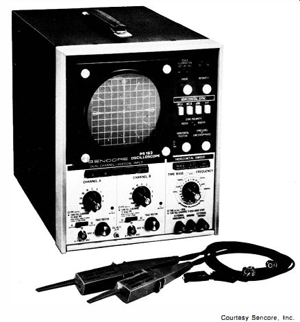
Fig. 1-1. A modern service-type oscilloscope.
| Home | Audio mag. | Stereo Review mag. | High Fidelity mag. | AE/AA mag. |
Introduction (this page; see below)
SECTION 1 Audio Tests and Measurements
SECTION 2 Impedance Measurements
SECTION 3 Television Tests and Measurements
SECTION 4 Digital Logic Tests
SECTION 5 Semiconductor Tests and Measurements
SECTION 6 Miscellaneous Applications
SECTION 7 Oscilloscope Performance Checks
Electronics technicians and television servicemen must learn to use the oscilloscope to its fullest potential. Often, the scope is used for only a limited number of tasks, far less than its versatility can provide.
This guide describes the potential uses of the oscilloscope. These uses range from audio tests and measurements, impedance measurements, television tests and measurements, semiconductor tests and measurements, digital logic tests, and miscellaneous applications, to oscilloscope performance tests.
The carefully written text is very generously illustrated to show how the individual tests are made. The illustrations include many actual photographs of waveforms that should be expected to be seen with the test being performed. Servicemen and technicians will want this guide to aid them in using the oscilloscope to its fullest potential.
Author:
Bob Middleton has been a professional free-lance technical writer in the electronics field for many years. His many books and magazine articles have proved invaluable to students, technicians, and engineers, because they have all been based on his own practical experience. His home workshop is filled with test equipment, receivers, and other equipment that he uses to check out every detail in preparing his many books Other Sams books by Mr. Middleton include 101 Ways to Use Your VOM, TVM & DVM, Radio Training Manual, Know Your Oscilloscope, Troubleshooting With the Oscilloscope, and many others.
----------------
In recent years electronics has undergone significant changes-some technicians would say revolutionary changes.
For example, the vacuum tube has almost disappeared from the scene (with the exception of the cathode-ray tube) . The bipolar transistor and field-effect transistor are now being extensively replaced by integrated circuits. Today, an integrated circuit operational amplifier could be confused with an older type of transistor, except for its more complex basing. Silicon control led rectifiers and related devices have made extensive inroads into the power-type bipolar transistors formerly used in television receivers. More dramatically, a digital revolution has occurred, and receiver tuning in particular is often accomplished by computer-type arrangements. Specialized television receivers provide digital-control led readouts of the operating channel and the time, with provision for extensive preprogramming of receiver operation. Digital filtering techniques are currently used for optimum separation of chroma and Y signals.
Evolution of the oscilloscope has kept pace with the rapid advance of electronics technology. Not too long ago the service-type oscilloscope illustrated in Fig. 1-1 was unheard of, although its predecessor was used in laboratories. Today, the television technician regards a dual-channel triggered-sweep oscilloscope as a basic service instrument. Bread-and-butter types of service oscilloscopes have vertical-amplifier bandwidths of approximately 5 MHz. Oscilloscopes designed for servicing computer-type circuitry, such as the one shown in Fig. 1-2, provide vertical bandwidth in the order of 30 MHz.
Professional varieties of oscilloscopes designed for comprehensive testing of high-speed digital circuitry (Fig. 1-3) feature vertical-amplifier bandwidths in the order of 100 MHz. "Old-old timers" are necessarily impressed also by the comparatively small dimensions and light weight of extra-high performance modern oscilloscopes, with respect to the large and heavy low-performance scopes used forty years ago.
This guide emphasizes practice, not theory. It is designed to show you how to do various jobs with your equipment as efficiently as possible. Information is presented without frills or double talk. Since a television set has the most involved electronic circuitry the average technician encounters, much of the text is related to testing the various sections and components of this type of receiver. This guide has a twofold purpose: to help you understand how to make waveform tests with an oscilloscope, and to show you how to analyze the waveforms produced by defective circuits. A careful study of these pages should make your work easier and more effective. Beginners will find it very helpful to make the various tests at the bench, as they proceed from one topic to the next. This provides a form of reinforced learning which facilitates both learning and retention of new material.
Most servicing is done with voltmeters. An oscilloscope is a voltmeter. It is a more complete voltmeter than a vom or dvm.
Courtesy Sencore, Inc.

Fig. 1-1. A modern service-type oscilloscope.
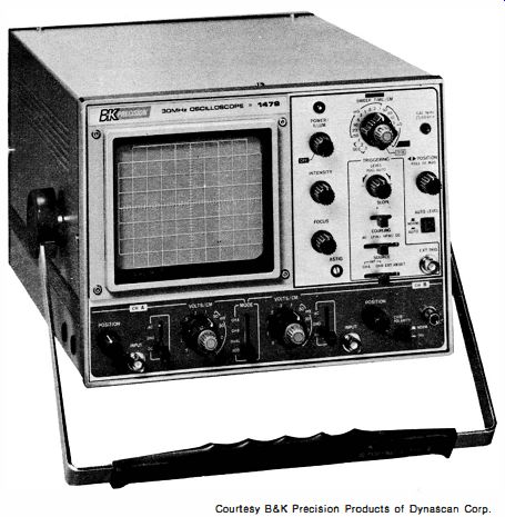
Fig. 1-2. A 30 MHz oscilloscope suitable for digital circuitry tests. Courtesy
B&K Precision Products of Dynascan Corp.
A scope gives more complete information than a vom (or dvm), because it shows how a voltage rises and falls in a receiver circuit. This variation is called the waveform of the voltage.
It is sometimes supposed that a scope is difficult to operate. Admittedly, a modern scope with triggered sweeps and dual channel display is more elaborate than the obsolescent instruments with free-running horizontal-deflection oscillators and single-channel display. However, it is still easier to learn how to use a scope than to learn how to ride a bicycle.
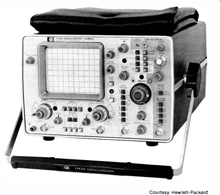
Fig. 1-3. A professional type of oscilloscope with a 100-MHz bandwidth.
Just as we can go places faster on a bicycle than on foot, we can troubleshoot tv receivers faster with a scope than with a voltmeter. For example, a meter cannot show whether a voltage is "ringing"-a scope does. A meter cannot show whether a signal is undistorted, clipped, or noisy-but a scope does.
A meter cannot indicate the occurrence of parasitics, cross talk, or phase shift-a scope shows these troubles at a glance.
Although this guide is not intended to be used as a textbook, if you have never used a scope before you will find it helpful to read the next few pages carefully. Here you will find a practical discussion of peak-to-peak, instantaneous, effective, and average values of sine waves, and how they tie in with the peak-to-peak values of complex tv waveforms.
Television service literature frequently refers to "peak-to-peak" voltage values. The ac voltage scales of a vom indicate rms voltage values. The meter movement in a vom responds to the average value of a rectified sine wave. Similarly, a rectified sine wave is displayed on the screen scope with its average value at the zero (beam- resting) level, when the scope is operated on its ac function. What do these various terms mean?

Fig. 1-4. A sine wave with important values.
A sine wave, with its important component values indicated, is given in Fig. 1-4. The highest value reached in any one direction by a waveform is called its peak value. The peak-to-peak voltage is equal to the total excursion from the positive peak to the negative peak. The two peaks of the sine wave have the same values on both positive and negative half-cycles-that is, a sine wave is a symmetrical waveform. The peak voltage is equal to one-half of the peak-to-peak voltage. The rms voltage (indicated by a vom) is equal to 0.707 of the peak voltage, as will be explained later in greater detail.
Of course, not all television waveforms are symmetrical . For example, consider the basic pulse waveform as shown in Fig. 1-5. Note that here the positive-peak voltage is not equal to the negative-peak voltage. However, the positive area of the wave-form is equal to its negative area. The sum of the positive-peak and negative-peak voltages is equal to the peak-to-peak volt-age. Note that any complex waveform will be displayed on the scope screen with its positive-peak voltage above the zero-volt axis, and with its negative-peak voltage below the zero-volt axis, when the scope is operated on its ac function.
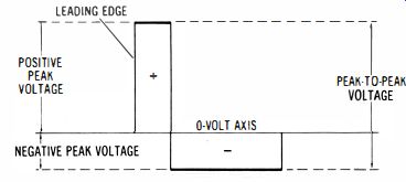
Fig. 1-5. Basic pulse waveform.
As can be seen in Fig. 1-4, the average value of a sine wave is zero-that is, the average value over one complete cycle is zero. It is sometimes puzzling to consider how we can speak of "10 milliamperes of alternating current," because the instantaneous value of the current is continuously changing, and the ave rage value of a complete cycle is zero. This puzzle is solved by first recognizing that, although the average value of an ac current is zero when tested with a dc meter, it does have some finite value when tested with an ac meter. Furthermore, when an alternating current is used for heating a soldering gun, or for lighting a crt filament for example, both the positive and the negative half-cycles of the waveform effectively produce heat and / or light, and do not cancel out. In other words, cancellation occurs only when the ac waveform is applied to a dc utilization device, such as a dc voltmeter.
Early in the development of the electrical industry, dc was used exclusively for heating, lighting, and power. Later, ac was found to be more economical to distribute and use, and ac power systems gradually displaced dc power systems. Now, the industry faced a new problem. A unit of voltage and current measurement was needed, whereby "1 10 volts" of ac would produce the same amount of heat, light, or power as "110 volts" of dc. What unit of ac measurement provides this equivalence? Equivalence is realized when ac is measured in terms of "effective" values. In other words, the effective value of an ac current corresponds to a dc value. A soldering gun will get just as hot when energized by 110 volts of dc as it will by 110 effective volts of ac. Usually, we speak of an effective value as an rms value. As noted in Fig. 1-4, the rms value is equal to 0.707 the peak value. Vom's are calibrated to read ac voltage and current in terms of rms values. The initials "rms" stand for "root mean square." Thus, we can compile the useful relations of sine-wave voltages:
PEAK-TO-PEAK VOLTAGE = 2 x PEAK VOLTAGE PEAK VOLTAGE = 1/2 x PEAK-TO-PEAK VOLTAGE RMS VOLTAGE = 0.707 x PEAK VOLTAGE PEAK VOLTAGE = 1.41 4 x RMS VOLTAGE PEAK-TO-PEAK VOLTAGE = 2.83 x RMS VOLTAGE
Furthermore, if you are using a dc scope, you need to know that when you apply a 1.S-volt battery across the vertical input terminals of the dc scope, the trace will move the same vertical height as when a 1.5 peak-to-peak sine wave voltage is applied.

Fig. 1-6. Sine wave and square wave with the same peak-to-peak voltage.
The peak-to-peak voltages of the sine wave and square wave in Fig. 1-6 are equal. On the other hand, it is clear that the rms voltages of the two waveforms are not equal. We know that the rms voltage for the sine wave is equal to 0.707 of its peak voltage. It will be realized by inspection of the square wave that its rms voltage is equal to its peak voltage. As a general rule, the rms value of a complex waveform cannot be determined by inspection. Service procedures require that rms values be measured only when heat or mechanical power is to be produced.
Otherwise, scope operators are concerned solely with peak and peak-to-peak voltages. Note, too, that an ac waveform may be associated with a dc level, as depicted in Fig. 1-7. In this situation, a dc scope provides measurement of the dc component level and of the peak-to-peak voltage of the ac component (sine wave in this example). As noted before, electronics technology is becoming increasingly more advanced. We must keep up with these advances if we are to remain competitive. Unless the full capabilities of oscilloscope use are clearly understood, it will become much more difficult in the future to properly service modern circuitry.

Fig. 1-7. How an ac waveform with a dc component is displayed on the screen
of a dc scope.
Also see: 50 Circuits Using 7400 Series IC's
Know Your Signal Generators [1965]