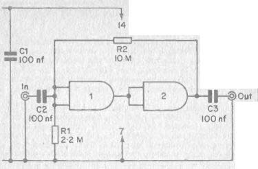
FIG. 33 A simple CMOS Schmitt trigger
| Home | Audio mag. | Stereo Review mag. | High Fidelity mag. | AE/AA mag. |
A Schmitt trigger is a fairly simple type of circuit, but it is one of the most useful of all electronic building blocks and is widely used in home constructor projects. Basically a Schmitt trigger is a circuit which can only have one of two stable states (high or low) at its output.
Which of these states the output assumes depends upon whether the input of the circuit is above or below a certain threshold voltage.
Most Schmitt trigger circuits have a degree of hysteresis, and so the threshold voltage at which the output goes high is above the threshold voltage at which it returns to the low state. In many applications this is a highly desirable feature, and in few it is absolutely essential, but it is usually necessary to have at least a small degree of hysteresis as otherwise the circuit would tend to become unstable with the input at or very close to the threshold voltage. Thus hysteresis is usually used whether it is essential to the basic operating principle of the circuit or not.
CMOS Schmitt trigger I.C.s are available, and the 4093 quad Schmitt trigger is one example. However, in most applications only a single Schmitt trigger is required, and it is more economical to connect a couple of inverters to form the circuit than it is to use a special I.C. (which arc not as cheap as simple gates). Either one or both of the unused inverters can sometimes be usefully employed in some other section of the circuit.
Simple CMOS Schmitt Trigger
There are several ways of connecting gates to form a Schmitt trigger circuit, and the method shown in Figure 33 is probably the simplest. Here the input of inverter 1 is tied to ground via R1, and so the output of this inverter is high. The output of inverter 2 will therefore be low.
If a positive input signal is now applied to the circuit this will take the input of inverter I positive, but it will not have any effect upon the circuit other than this unless the input signal reaches an amplitude which is equal to the transfer voltage of inverter 1. When this happens, the output of inverter 1 will swing down towards the negative supply rail voltage, and this will cause the output of inverter 2 to start to go high. As it does so it feeds a positive voltage to the input of inverter 1 via R2, and this causes the output of inverter 1 to go more negative. This in turn sends the output of inverter 2 more positive. This causes a further positive voltage to be fed to inverter 1 input by way of R2, and this regenerative action will continue until the output of the circuit is fully positive.
---------
A Schmitt trigger is a fairly simple type of circuit, but it is one of the most useful of all electronic building blocks and is widely used in home constructor projects. Basically a Schmitt trigger is a circuit which can only have one of two stable states (high or low) at its output.
Which of these states the output assumes depends upon whether the input of the circuit is above or below a certain threshold voltage.
Most Schmitt trigger circuits have a degree of hysteresis, and so the threshold voltage at which the output goes high is above the threshold voltage at which it returns to the low state. In many applications this is a highly desirable feature, and in few it is absolutely essential, but it is usually necessary to have at least a small degree of hysteresis as otherwise the circuit would tend to become unstable with the input at or very close to the threshold voltage. Thus hysteresis is usually used whether it is essential to the basic operating principle of the circuit or not.
CMOS Schmitt trigger I.C.s are available, and the 4093 quad Schmitt trigger is one example. However, in most applications only a single Schmitt trigger is required, and it is more economical to connect a couple of inverters to form the circuit than it is to use a special I.C. (which are not as cheap as simple gates). Either one or both of the unused inverters can sometimes be usefully employed in some other section of the circuit.
Simple CMOS Schmitt Trigger
There are several ways of connecting gates to form a Schmitt trigger circuit, and the method shown in Figure 33 is probably the simplest.
Here the input of inverter 1 is tied to ground via R1 , and so the output of this inverter is high. The output of inverter 2 will therefore be low.
If a positive input signal is now applied to the circuit this will take the input of inverter 1 positive, but it will not have any effect upon the circuit other than this unless the input signal reaches an amplitude which is equal to the transfer voltage of inverter 1. When this happens, the output of inverter 1 will swing down towards the negative supply rail voltage, and this will cause the output of inverter 2 to start to go high. As it does so it feeds a positive voltage to the input of inverter 1 via R2, and this causes the output of inverter 1 to go more negative.
This in turn sends the output of inverter 2 more positive. This causes a further positive voltage to be fed to inverter 1 input by way of R2, and this regenerative action will continue until the output of the circuit is fully positive.
FIG. 33 A simple CMOS Schmitt trigger
In practice this all happens extremely rapidly, and virtually the instant the input voltage reaches the transfer voltage of inverter 1, the output assumes the high state.
If the input signal now begins to swing back towards the negative supply rail, a point will of course be reached where the input of inverter ' 1 is taken below the transfer voltage, and the output will start to swing negative. A regenerative circuit action will then once again take place and the output will quickly go fully low.
Hysteresis is introduced by the fact that once the output has gone high, the voltage through R2 is added to the input signal. This means that the input signal must go well below the transfer voltage before the circuit will return to its original state. The circuit will not normalize until the voltage from the output plus the input signal voltage equals a total which is less than the transfer voltage of inverter 1.
This basic circuit has many uses, and it can, for example, be used to produce a squarewave output from a sine or triangular input waveform.
It can also be used to speed up a slowly rising or falling waveform, and it is often necessary to do this when using logic devices. This is due to the fact that many logic devices will not function reliably unless they are operated by a fast rising waveform, and CMOS counters and flip flop for example, must be driven by an input signal having a risetime of 5 micro -seconds or less.
In practice this all happens extremely rapidly, and virtually the instant the input voltage reaches the transfer voltage of inverter 1, the output assumes the high state.
If the input signal now begins to swing back towards the negative supply rail, a point will of course be reached where the input of inverter 1 is taken below the transfer voltage, and the output will start to swing negative. A regenerative circuit action will then once again take place and the output will quickly go fully low.
Hysteresis is introduced by the fact that once the output has gone high, the voltage through R2 is added to the input signal. This means that the input signal must go well below the transfer voltage before the circuit will return to its original state. The circuit will not normalize until the voltage from the output plus the input signal voltage equals a total which is less than the transfer voltage of inverter 1.
This basic circuit has many uses, and it can, for example, be used to produce a squarewave output from a sine or triangular input waveform.
It can also be used to speed up a slowly rising or falling waveform, and it is often necessary to do this when using logic devices. This is due to the fact that many logic devices will not function reliably unless they are operated by a fast rising waveform, and CMOS counters and flip flop for example, must be driven by an input signal having a risetime of 5 micro-seconds or less.
Light Detector
Schmitt triggers are not only used in A.C. applications, and are frequently used in D.C. circuitry. In this type of application it is usually the role of the circuit to ensure that a definite output state is obtained, with no intermediate ones being possible.
An example of this is the simple light detector circuit which is shown in Figure 34. This type of circuit is used to close a set of relay contacts when the light level falling on a photocell exceeds a certain level. Such devices can be used in burglar alarms and for many other purposes.
It is usually necessary for the unit to draw a very low standby current so that economic battery operation is feasible. In the circuit of Figure 34 the Schmitt trigger ensures that this is achieved. VR1 is adjusted so that the output of the Schmitt trigger circuit is normally low, and no significant base current is supplied to Tr1. This transistor is therefore cut off and the relay is not activated.
When the light level falling on PCC1 exceeds a certain threshold level, the resistance of this cell will have dropped to a low enough level to cause the voltage at the junction of VR1 and PC C1 to rise above the trigger voltage of the Schmitt trigger. Its output will quickly go to the high state and Tr1 will turn on. The relay will then be activated.
Under normal conditions the Schmitt trigger and the output transistor draw no current, and the only supply current which flows is the small current through PCC1 and VR1. The circuit would still work if the trigger circuit and R3 were to be omitted, with the junction of PCC1 and V R1 then being connected direct to Tr1 base. However, with the circuit in the normal or off state it would be quite possible for a small base current to be fed to Tr1. This would cause it to draw a significant collector current which although too small to activate the relay, could discharge the batteries over a period of time.
Darkness Detector
In many applications it is necessary to have a circuit which operates a relay when the light level goes below a certain level, rather than when it goes above a certain level. It is quite simple to convert the circuit of Figure 34 to do this and there are several ways of doing it. Probably the most simple one is simply to transpose VR1 and PC C1. The voltage at the junction of these two devices will then rise with decreasing light level, and the required circuit action is thus provided.
Latching Version
In alarm circuits and certain other applications it is necessary to have a circuit that will remain on once it has been triggered. It is an easy Light Detector Schmitt triggers are not only used in A.C. applications, and are frequently used in D.C. circuitry. In this type of application it is usually the role of the circuit to ensure that a definite output state is obtained, with no intermediate ones being possible.
An example of this is the simple light detector circuit which is shown in Figure 34. This type of circuit is used to close a set of relay contacts when the light level falling on a photocell exceeds a certain level. Such devices can be used in burglar alarms and for many other purposes.
It is usually necessary for the unit to draw a very low standby current so that economic battery operation is feasible. In the circuit of Figure 34 the Schmitt trigger ensures that this is achieved. VR1 is adjusted so that the output of the Schmitt trigger circuit is normally low, and no significant base current is supplied to Tr1 . This transistor is therefore cut off and the relay is not activated.
When the light level falling on PCC1 exceeds a certain threshold level, the resistance of this cell will have dropped to a low enough level to cause the voltage at the junction of VR1 and PCC1 to rise above the trigger voltage of the Schmitt trigger. Its output will quickly go to the high state and Tr1 will turn on. The relay will then be activated.
Under normal conditions the Schmitt trigger and the output transistor draw no current, and the only supply current which flows is the small current through PCC1 and VR1. The circuit would still work if the trigger circuit and R3 were to be omitted, with the junction of PCC1 and VR1 then being connected direct to Tr1 base. However, with the circuit in the normal or off state it would be quite possible for a small base current to be fed to Tr1 . This would cause it to draw a significant collector current which although too small to activate the relay, could discharge the batteries over a period of time.
Darkness Detector
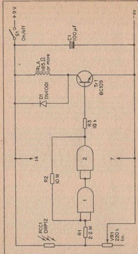
FIG.34 A simple light detector circuit
In many applications it is necessary to have a circuit which operates a relay when the light level goes below a certain level, rather than when it goes above a certain level. It is quite simple to convert the circuit of Figure 34 to do this and there are several ways of doing it. Probably the most simple one is simply to transpose VR1 and PCC1. The voltage at the junction of these two devices will then rise with decreasing light level, and the required circuit action is thus provided.
Latching Version
In alarm circuits and certain other applications it is necessary to have a circuit that will remain on once it has been triggered. It is an easy matter to modify the circuit of Figure 34 to provide latching, and the revised circuit diagram appears in Figure 35.
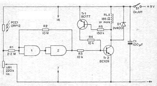
FIG 35 A latching light detector circuit
This operates in exactly the same way as the original circuit until the relay is activated. Then the voltage across the relay, which was previously zero, rises to several volts, and a base current is supplied to Tr1 by way of current limiting resistor R5. This turns Tr1 on, and a base current will be supplied to Tr2 via Tr1 emitter and collector and current limiting resistor R4.
Even if the output of the Schmitt trigger now returns to the low state, Tr2 will not be switched off as it will still be receiving a base current from Tr1. The circuit therefore latches in the on state once it has been triggered, with Tr1 and Tr2 providing a sort of thyristor action. Like the circuit of Figure 34, this circuit can be built as a darkness detector by swopping over VR1 and PC C1.
Automatic Parking Light
In applications where a light switch is to be used to operate a low voltage D.C. load it is usually possible to use a relay-less circuit. An automatic parking light for a car is one such example, and a suitable circuit is shown in Figure 36.
Here the circuit is triggered when the light level falls below a level which causes the voltage at the junction of VR1 and PCC1 to exceed the trigger voltage of the Schmitt trigger. The trigger circuit then provides a base current to a high gain Darlington pair using Tr1 and 'Tr2. Tr2 is a power transistor which is capable of handling the relatively high current drawn by a parking light. S1 enables the light to be turned on independently of the automatic circuitry.
In this circuit the current consumption of the device is of secondary importance since it will be powered from a high capacity car battery.
However, it is obviously desirable to have the lamp switching cleanly from one state to the other. Perhaps less obviously it is necessary for the circuit to avoid intermediate output states in order to illuminate the possibility of damage to Tr2 due to overheating.
This could occur if Tr2 was partially switched on with about half the supply voltage being present at its collector, as it would then have to dissipate several watts of power. This could be overcome by using a large amount of heatsinking for Tr2, but it is probably better to use a trigger circuit, as Tr2 can then only rest in the hard on or fully off state. The dissipation in either case can only be low, as when it is turned hard on very little voltage is produced across it, and when it is turned hard off it passes no significant current. It will dissipate a significant amount of power when it is turned on, and if a high current lamp is being controlled a certain amount of heatsinking will be necessary, but this will only need to be minimal.
This operates in exactly the same way as the original circuit until the relay is activated. Then the voltage across the relay, which was previously zero, rises to several volts, and a base current is supplied to Tr1 by way of current limiting resistor R5. This turns Tr1 on, and a base current will be supplied to Tr2 via Tr1 emitter and collector and current limiting resistor R4.
Even if the output of the Schmitt trigger now returns to the low state, Tr2 will not be switched off as it will still be receiving a base current from T r1 . The circuit therefore latches in the on state once it has been triggered, with Tr1 and Tr2 providing a sort of thyristor action. Like the circuit of Figure 34, this circuit can be built as a darkness detector by swopping over VR1 and PCC1.
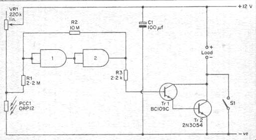
FIG. 36 An automatic parking light
In all the light switches just described it is possible to adjust the circuit by means of VR1 to produce a switching threshold at almost any required light intensity.
Touch Switch
A Schmitt trigger can be used as the basis of a simple touch switch, where it ensures that the circuit switches briskly from one state to the other and does not take up a stable intermediate state. It thus provides an action which is very similar to a conventional mechanical switch.
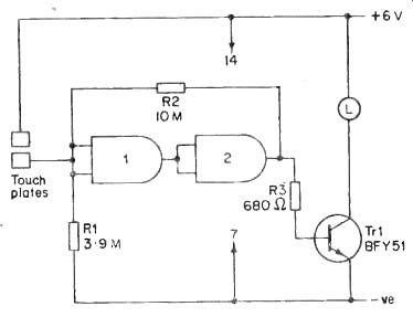
FIG. 37 Touch operated torch circuit
A simple touch switch circuit is shown in Figure 37 , and this shows how a CMOS Schmitt trigger can be used as the basis of a novel home made torch. The circuit has other possible uses of course, and any small D.C. load can be connected in place of the lamp. Other loads can be controlled by using a relay in the collector circuit of Tr1, and if this is done it will also be necessary to include a protective diode in this part of the circuit.
Operation of the circuit is very straightforward. The Schmitt trigger is arranged so that its input and output are both normally in the low condition, and Tr1 is therefore normally cut off. When the touch contacts are bridged by the operator's finger a current will flow from the positive supply rail and through R1. In effect, the skin resistance of the operating finger and R1 together form a potential divider, and In all the light switches just described it is possible to adjust the circuit by means of VR1 to produce a switching threshold at almost any required light intensity.
Touch Switch
A Schmitt trigger can be used as the basis of a simple touch switch, where it ensures that the circuit switches briskly from one state to the other and does not take up a stable intermediate state. It thus provides an action which is very similar to a conventional mechanical switch.
A simple touch switch circuit is shown in Figure 37, and this shows how a CMOS Schmitt trigger can be used as the basis of a novel home made torch. The circuit has other possible uses of course, and any small D.C. load can be connected in place of the lamp. Other loads can be controlled by using a relay in the collector circuit of Tr1 , and if this is done it will also be necessary to include a protective diode in this part of the circuit.
Operation of the circuit is very straightforward. The Schmitt trigger is arranged so that its input and output are both normally in the low condition, and Tr1 is therefore normally cut off. When the touch contacts are bridged by the operator's finger a current will flow from the positive supply rail and through R1 . In effect, the skin resistance of the operating finger and R1 together form a potential divider, and provided the voltage at their junction is above the threshold voltage of the Schmitt trigger, this circuit will assume the high state at the output.
It then supplies a base current to Tr1 which is, in consequence, biased hard on. Power is then supplied to the lamp which should have a current consumption of no more than about 100 mA.
When the operator's finger is removed from the touch contacts the Schmitt trigger reverts to its original state and the lamp is switched off.
Over Temperature Indicator
In this application it is the purpose of the Schmitt trigger to ensure that an erroneous indication is not produced. This is simply a circuit which indicates by means of a lamp any rise in temperature above a preset threshold level. If the triggering were to be left out, then the lamp would begin to glow dimly as the temperature approached the threshold level. This could be confusing, and if the unit is battery powered it could result in the batteries having a very short working life. The circuit diagram of the unit appears in Figure 38.
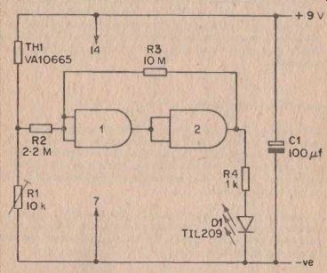
FIG. 38 Over temperature indicator circuit
TH1 and R1 are connected as a potential divider at the input of the trigger circuit. TH1 is a negative temperature coefficient thermistor, and its resistance therefore decreases with increasing temperature. R1 TH1 and R1 are connected as a potential divider at the input of the trigger circuit. TH1 is a negative temperature coefficient thermistor, and its resistance therefore decreases with increasing temperature. R1 is adjusted so that the voltage produced by this potential divider reaches the trigger threshold of the Schmitt trigger at the required threshold temperature. When the output of the Schmitt trigger goes high, power is supplied to the L.E.D. indicator, D1.
When the lamp is in the off state the circuit only consumes about 1 mA from the supply lines, and this is the power which flows through the thermistor and R1. A reasonable battery life can be obtained by using a large capacity battery to power the unit, but in many cases it will be better to use a small battery and connect a push to make non -locking push button switch in series with the positive supply lead. The unit will then only consume power when this push switch is -operated. Obviously in some applications this form of periodic monitoring will not be suitable, but it is preferable to use it wherever it is practical to do so.
A wide range of threshold temperatures can be provided by R1, and the actual operating range of the circuit extends from more than 100 degrees Fahrenheit to less than 0 degrees Fahrenheit. It is therefore a very versatile circuit.
It is not essential for the thermistor to be built into the main unit, and there is no reason why it should not be remotely located from the rest of the unit. Quite a long connecting cable can be used between the thermistor sensor and the rest of the unit if necessary. The unit could thus be used as a rue alarm for an outbuilding, or in some similar Under Temperature Version The circuit of Figure 38 is easily modified to function as an under temperature indicator, and it is merely necessary to transpose the positions of R1 and Till. The circuit could then be used, for example, as a frost alarm, and could be used by gardeners or in automotive applications. The operating temperature range is the same as for the original version of the unit.
By using all four gates of a 4001 or 4011 I.C. it would be possible to make both versions of the unit using a single device. The unit could then be adjusted so that it would indicate any temperature deviation outside two preset limits.
Over Temperature Alarm
This is basically the same circuit as the over temperature indicator, but the output of the Schmitt trigger is used to control an audible slams circuit rather than an indicator light. The circuit diagram of this unit is shown in Figure 39.
is adjusted so that the voltage produced by this potential divider reaches the trigger threshold of the Schmitt trigger at the required threshold temperature. When the output of the Schmitt trigger goes high, power is supplied to the L.E.D. indicator, D1.
When the lamp is in the off state the circuit only consumes about 1 mA from the supply lines, and this is the power which flows through the thermistor and R1 . A reasonable battery life can be obtained by using a large capacity battery to power the unit, but in many cases it will be better to use a small battery and connect a push to make non-locking push button switch in series with the positive supply lead. The unit will then only consume power when this push switch is operated. Obviously in some applications this form of periodic monitoring will not be suitable, but it is preferable to use it wherever it is practical to do so.
A wide range of threshold temperatures can be provided by R1, and the actual operating range of the circuit extends from more than 100 degrees Fahrenheit to less than 0 degrees Fahrenheit. It is therefore a very versatile circuit.
It is not essential for the thermistor to be built into the main unit, and there is no reason why it should not be remotely located from the rest of the unit. Quite a long connecting cable can be used between the thermistor sensor and the rest of the unit if necessary. The unit could thus be used as a fire alarm for an outbuilding, or in some similar application.
Under Temperature Version
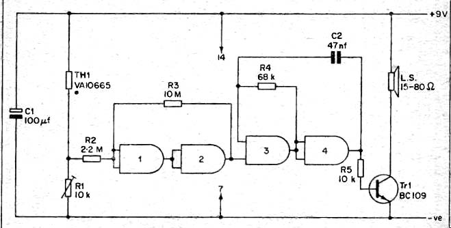
FIG. 39 Over temperature alarm circuit (use 4011 only)
The circuit of Figure 38 is easily modified to function as an under temperature indicator, and it is merely necessary to transpose the positions of R1 and TH1 . The circuit could then be used, for example, as a frost alarm, and could be used by gardeners or in automotive applications. The operating temperature range is the same as for the original version of the unit.
By using all four gates of a 4001 or 4011 I.C. it would be possible to make both versions of the unit using a single device. The unit could then be adjusted so that it would indicate any temperature deviation outside two preset limits.
Over Temperature Alarm
This is basically the same circuit as the over temperature indicator, but the output of the Schmitt trigger is used to control an audible alarm circuit rather than an indicator light. The circuit diagram of this unit is shown in Figure 39.
Inverter 3 and inverter 4 are connected as an astable multi-vibrator which operates at a frequency of a few hundred Hz. This feeds a common emitter amplifier using Tr1 , and this in turn operates a loudspeaker.
The multivibrator is blocked and cannot operate unless the output of the Schmitt trigger is high, and the alarm does not therefore sound until the circuit has been triggered.
The quiescent current and operating temperature range of this circuit are the same as for the over temperature indicator. The unit can be converted to an under temperature alarm by swopping over R1 and TH1.
It is important to note that this circuit will only operate using a 4011 I.C., and a 4001 is not suitable in this instance.
Providing R1 with the correct adjustment is quite simple and is the same for this circuit and for the over temperature indicator. The thermistor is heated or cooled to the required threshold temperature, and then R1 is adjusted for the lowest resistance which causes the indicator lamp to conic on or the alarm to sound, as appropriate.
For the under temperature versions the procedure is much the same, the only difference being that R1 must be adjusted for the highest resistance which keeps the indicator lamp on or the alarm sounding.
Electronic
Two simple timers which provide an audible output at the end of a variable timing period have already been covered. These circuits were limited to a maximum timing interval of only about 10 seconds, because using a longer time constant would result in the tone generator being turned on only gradually, which would obviously not be satis factory.
The timer circuit shown in Figure 40 is basically similar to the original one (see Figure 12) in that it uses an R-C timing network and an astable multivibrator tone generator. However, instead of the tone generated being fed to the output stage/speaker via an enabling gate, it is fed direct to this arrangement. The multivibrator itself is control led on this occasion, via a control voltage which is fed to one input of gate 4. This terminal is normally low and the astable circuit is muted.
The output of gate 5 is also normally low with Tr1 being cut off and passing no current. This is very important, as if it were normally high, Tr1 would be biased on and there would be a very high static current consumption.
Gates 2 and 3 are used as the Schmitt trigger, and this has its input fed from an inverter which in turn has its input fed from the R-C timing network. C1 is the capacitive part of the timing network and R1 – VR1 are the resistive part.
Inverter 3 and inverter 4 are connected as an astable multi-vibrator which operates at a frequency of a few hundred Hz. This feeds a common emitter amplifier using Tr1 , and this in turn operates a loudspeaker.
The multivibrator is blocked and cannot operate unless the output of the Schmitt trigger is high, and the alarm does not therefore sound until the circuit has been triggered.
The quiescent current and operating temperature range of tills circuit are the same as for the over temperature indicator. The unit can be converted to an under temperature alarm by swopping over R1 and TH1 .
It is important to note that this circuit will only operate using a 4011 I.C., and a 4001 is not suitable in this instance.
Providing R1 with the correct adjustment is quite simple and is the same for this circuit and for the over temperature indicator. The thermistor is heated or cooled to the required threshold temperature, and then R1 is adjusted for the lowest resistance which causes the indicator lamp to come on or the alarm to sound, as appropriate.
For the under temperature versions the procedure is much the same, the only difference being that R1 must be adjusted for the highest resistance which keeps the indicator lamp on or the alarm sounding.
Electronic Egg Timer
Two simple timers which provide an audible output at the end of a variable timing period have already been covered. These circuits were limited to a maximum timing interval of only about 10 seconds, , because using a longer time constant would result in the tone generator being turned on only gradually, which would obviously not be satisfactory.
The timer circuit shown in Figure 40 is basically similar to the original one (see Figure 12) in that it uses an R-C timing network and an astable multivibrator tone generator. However, instead of the tone generated being fed to the output stage/speaker via an enabling gate, it is fed direct to this arrangement. The multivibrator itself is control led on this occasion, via a control voltage which is fed to one input of gate 4. This terminal is normally low and the astable circuit is muted.
The output of gate 5 is also normally low with Tr1 being cut off and passing no current. This is very important, as if it were normally high, Tr1 would be biased on and there would be a very high static current consumption.
Gates 2 and 3 are used as the Schmitt trigger, and this has its input fed from an inverter which in turn has its input fed from the R -C timing network. C1 is the capacitive part of the timing network and R1 - VR1 are the resistive part.
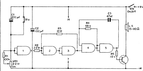
FIG. 40 Electronic egg timer circuit (use 4011 only)
S1 a opens when the on/off switch (Sib) is closed, and this starts the timing interval. C1 begins to charge up through VR1 and R1 and eventually the voltage across R1 and VR1 will fall to the transfer voltage of gate 1. When this happens, the output voltage of gate 1 will gradually begin to rise. After a short while its output voltage will reach the trigger voltage of the Schmitt trigger circuit, and the output of inverter 3 will immediately go high. This turns on the multivibrator and the audible alarm tone is produced from the speaker.
When the unit is switched off, S1 a discharges C1 and the unit is then ready to start another timing period when it is switched on once again.
VR1 enables the length of the timing interval to be varied from less than 30 seconds to more than 6 minutes, and the unit is thus suitable for use as an egg timer, or indeed for a multitude of uses in the house.
A timer of this type can be much more useful than one might imagine.
A dial calibrated in minutes should be marked around the control knob of VR1, and there is unfortunately no quick way of doing this. It is a matter of finding all the calibration points using a process of trial and error.
Note that this circuit can only be built using a 4011 IC., as gate 4 must be a NAND type. In actual fact it requires two I.C.s, since five gates are employed in the circuit and only four are contained in each 4011 I.C.
Under Voltage Indicator
Many pieces of 9 volt battery operated equipment, particularly in the field of test equipment, use a stabilized supply rail of between 5.6 and 7.5 V. Malfunction of the equipment can occur if this voltage should fall below its nominal level due to battery ageing, but many pieces of gear do not incorporate any form of battery check facility. This can be added to such equipment using the simple circuit shown in Figure 41.
The upper and lower threshold voltages of a CMOS Schmitt trigger are determined by the individual characteristics of the gates employed and by the supply rail potential. This circuit is therefore powered from a stabilized supply so that these voltages are not significantly affected by variations in the supply rail potential. This stabilized potential has been made lower than that of the monitored voltage for obvious reasons.
The two inverters are connected as a simple Schmitt trigger which has its input fed from the monitored voltage via a preset potentiometer ( R1). R1 is adjusted so that the Schmitt trigger is normally in the high state, with the voltage at its slider being fractionally higher than the lower threshold voltage of the Schmitt trigger. An L.E.D. indicator (DI) and current limiting resistor (R4) are connected at the output of S la opens when the on/off switch (Sib) is closed, and this starts the timing interval. C1 begins to charge up through VR1 and R1 and eventually the voltage across R1 and VR1 will fall to the transfer voltage of gate 1. When this happens, the output voltage of gate 1 will gradually begin to rise. After a short while its output voltage will reach the trigger voltage of the Schmitt trigger circuit, and the output of inverter 3 will immediately go high. This turns on the multivibrator and the audible alarm tone is produced from the speaker.
When the unit is switched off, S1a discharges C1 and the unit is then ready to start another timing period when it is switched on once again.
VR1 enables the length of the timing interval to be varied from less than 30 seconds to more than 6 minutes, and the unit is thus suitable for use as an egg timer, or indeed for a multitude of uses in the house.
A timer of this type can be much more useful than one might imagine.
A dial calibrated in minutes should be marked around the control knob of VR1, and there is unfortunately no quick way of doing this. It is a matter of finding all the calibration points using a process of trial and error.
Note that this circuit can only be built using a 4011 I.C., as gate 4 must be a NAND type. In actual fact it requires two I.C.s, since five gates are employed in the circuit and only four are contained in each 4011 I.C.
Under Voltage Indicator
Many pieces of 9 volt battery operated equipment, particularly in the field of test equipment, use a stabilized supply rail of between 5.6 and 7.5 V. Malfunction of the equipment can occur if this voltage should fall below its nominal level due to battery ageing, but many pieces of gear do not incorporate any form of battery check facility. This can be added to such equipment using the simple circuit shown in Figure 41.
The upper and lower threshold voltages of a CMOS Schmitt trigger are determined by the individual characteristics of the gates employed and by the supply rail potential. This circuit is therefore powered from a stabilized supply so that these voltages are not significantly affected by variations in the supply rail potential. This stabilized potential has been made lower than that of the monitored voltage for obvious reasons.
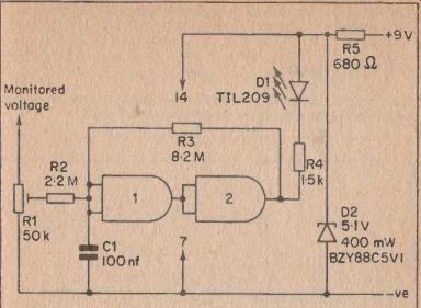
FIG. 41 Under voltage indicator circuit.
The two inverters are connected as a simple Schmitt trigger which has its input fed from the monitored voltage via a preset potentiometer (R1) . R1 is adjusted so that the Schmitt trigger is normally in the high state, with the voltage at its slider being fractionally higher than the lower threshold voltage of the Schmitt trigger. An L.E.D. indicator (D1) and current limiting resistor (R4) are connected at the output of the Schmitt trigger, and these are not supplied with power unless the output of the trigger circuit goes low.
This is precisely what will happen if the monitored voltage should fall significantly, as the input voltage to the Schmitt trigger will fall below the lower threshold voltage and will cause the circuit to change state.
The circuit thus indicates any significant fall in the monitored voltage. The circuit is very easy to set up, and it is merely necessary to adjust R1 for what is virtually the lowest slider voltage which does not cause D1 to come on. It is best not to take this voltage too close to the lower threshold voltage of the Schmitt trigger, as it must be remembered that voltage stabilizer circuits are all less than perfect. There is usually a certain decrease in a stabilized rail which is derived from a battery supply, even before the battery voltage drops below a suitable working level.
It is possible to have the monitor circuit permanently connected to the un-stabilized supply, but the unit will consume a current of about 6 mA under quiescent conditions, this being the current used by the zener regulator circuit (R5 and D2). It could therefore significantly reduce the working life of the battery.
A more practical solution is to connect the unit to the positive supply by way of a push to make non -locking push button switch. This can then be periodically operated in order to check whether or not the battery needs replacing.
Capacitor C1 is needed in order to suppress transient voltages which could cause the circuit to operate erratically.
Over Voltage Version
The circuit of Figure 41 can easily be modified to act as an over voltage indicator, and the appropriate circuit appears in Figure 42.
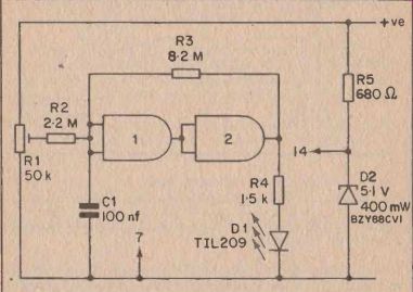
FIG 42 Over voltage indicator circuit.
Here the Schmitt triggers output is normally in the low state, and the L.E.D. indicator circuit, which is now connected between the trigger output and the negative supply, does not receive any current. If the supply voltage goes above a predetermined level, the voltage at the input of the trigger circuit will exceed the upper threshold voltage, and the output of the circuit will go high. Current will then be supplied to D1 which will, in consequence, come on and indicate the excessive supply voltage.
The circuit can be adjusted to operate at any voltage from about 3 to 15 volts. In order to give R1 the correct setting it is necessary to connect the unit to a supply voltage which is equal to the required threshold voltage. R1 is then adjusted for the lowest slider voltage which causes D1 to come on.
Due to the fact that the circuit has a degree of hysteresis, it is necessary to start with R1 slider at minimum voltage, and then gradually increase this until DI lights up. Starting with R1 slider at maximum voltage Capacitor C1 is needed in order to suppress transient voltages which could cause the circuit to operate erratically.
Over Voltage Version
The circuit of Figure 41 can easily be modified to act as an over voltage indicator, and the appropriate circuit appears in Figure 42.
Here the Schmitt triggers output is normally in the low state, and the L.E.D. indicator circuit, which is now connected between the trigger output and the negative supply, does not receive any current. If the supply voltage goes above a predetermined level, the voltage at the input of the trigger circuit will exceed the upper threshold voltage, and the output of the circuit will go high. Current will then be supplied to D1 which will, in consequence, come on and indicate the excessive supply voltage.
The circuit can be adjusted to operate at any voltage from about 3 to 15 volts. In order to give R1 the correct setting it is necessary to connect the unit to a supply voltage which is equal to the required threshold voltage. R1 is then adjusted for the lowest slider voltage which causes D1 to come on.
Due to the fact that the circuit has a degree of hysteresis, it is necessary to start with R1 slider at minimum voltage, and then gradually increase this until D1 lights up. Starting with R1 slider at maximum voltage and then turning it back until the L.E.D. goes out is not correct. If this is done, the lower threshold voltage of the Schmitt trigger will be reached when the input voltage reaches the overload point, whereas it should be the upper threshold voltage that is reached. The circuit would then fail to respond to a slightly excessive voltage.