The horizontal and vertical deflection circuits control the horizontal and vertical scanning that produce the picture on the television screen. In other words, the deflection circuits cause the electron beams to move in a manner that produces a scanning raster on the screen:
1. The sync separator divides the sync signals into horizontal signals and vertical signals, removes extraneous signals, such as video signals, from the sync signals, amplifies the signals, and outputs the signals to the appropriate deflection circuits.
2. The horizontal deflection circuit moves the electron beams from the left to the right on the screen, then back to the left 15,734 times every second. The horizontal scan operates at a frequency of 15.734 kHz.

FIG. 1. The deflection circuits (shaded).
3. The vertical deflection circuit moves the electron beams from top to the bottom of the screen, then back to the top 60 times every second.
The vertical scan operates at a frequency of 60 Hz.
A basic deflection circuit diagram is shown in FIG. 1.
The horizontal output circuit also produces the high voltage needed to power the CRT and other circuits in the chassis. This use of the horizontal output circuit is described in Section 4, Troubleshooting Power Supplies and Section 8, Troubleshooting High-Voltage Circuits.
If you suspect that an IC is faulty, gently press the IC to make sure the pins are correctly seated if the IC is mounted in a plug-in socket. If the problem persists, continue with the troubleshooting procedures. Measure voltages on all pins. Also, check the solder connections on all pins.
The configurations of ICs and components that make up the deflection circuits can vary according to the manufacturer. Refer to the DATASHEET schematic for the television’s brand and model for the exact composition of the circuits and component values.
Sync Separator
When the television station transmits the composite video signal, shown in FIG. 2, it contains the video signal, the audio signal, the color signal and the sync signal. The sync signal synchronizes the horizontal and vertical scanning on the CRT screen with the original signal broadcast from the station.
The video processing circuits separate the sync signals from the video signals. The sync separator circuit, like the one shown in FIG. 3, filters out any extraneous signals, including video and noise. The clean sync signals are output to low-pass filters that separate the 60 Hz vertical signals from the 15.750 kHz horizontal signals.

FIG. 2. A composite video signal.
The first stage in the sync separator separates the sync signals from the video signal and any noise that remains in the signal. Then, the vertical integrator and the sync amplifier select the vertical sync signal from the total sync signal, amplifies the vertical sync signal, and sends it to the vertical deflection circuits. In the same manner, the horizontal differentiator selects the horizontal sync signal, amplifies the horizontal sync signal, and sends it to the horizontal deflection circuits.
Picture problems, like those shown in FIG. 4, suggest that the sync separator is not working properly.

FIG. 3. A sync separator circuit, internal to IC.
Troubleshooting the Sync Separator

FIG. 4. Sync signal problems: moderate loss of vertical sync (a); moderate
loss of horizontal sync (b); severe loss of horizontal sync (c); loss of horizontal
and vertical sync (d).
Loss of vertical sync causes the picture to roll up and roll down, and not lock vertically, even when you adjust the vertical hold. This problem suggests that the vertical integrator/amplifier stage is faulty and cannot maintain the vertical hold. If the vertical deflection circuits were faulty, the picture would roll either up or down, but not in both directions. Use an oscilloscope to check the waveform from the output of the vertical integrator/amplifier stage. If there are horizontal signals or noise in the waveform, the vertical integrator/amplifier is not selecting only the vertical signals.
If you see horizontal tearing or just horizontal scan lines, try to adjust the horizontal hold. If the horizontal hold control does not lock the picture horizontally, check the horizontal differentiator/amplifier or the APC (automatic phase control) circuit, described later in this Section. Use an oscilloscope to check the waveform from the output of the horizontal differentiator/amplifier stage. If there are vertical signals or noise in the waveform, the horizontal differentiator/amplifier is not selecting only the horizontal signals. See the section on the APC, later in this Section, for more information on troubleshooting the APC.
A problem with multiple symptoms, such as horizontal tearing and vertical rolling, and the blanking bar appearing on the screen, indicates a problem before the sync separator circuit. Look carefully at the waveform output from the video detector circuit. If the video detector output signal is correct, trace the signal through the sync separator. If the video detector output signal is not correct, measure the outputs and inputs for all circuits that process the sync signal. Most sync problems in this area occur at or after the video the detector. IF stages rarely cause this type of problem.
FIG. 5. An APC circuit.
As you are troubleshooting the sync circuit IC, check the supply voltages to the IC, and check all components and connections around the IC. If the source of the problem is the sync separator circuit IC, replace the IC.
Automatic Phase Control (APC)
The APC circuit, shown in FIG. 5, is part of the horizontal deflection IC and keeps the horizontal oscillator synchronized with the sync signal sent from the television station. This circuit rarely is deflective.
There are two inputs into the APC. One input is the sync signal pulse from the sync separator. The other input is a reference signal from the horizontal oscillator from any circuit past the horizontal oscillator. The APC compares the horizontal sync pulse and the reference signal for a phase difference. If it detects a difference, the APC produces a correction voltage. The correction is made when the polarity of the correction voltage adds to or subtracts from the horizontal oscillator’s normal bias. The correction output voltage varies according to how close the two inputs are. The correction voltage is output to the horizontal oscillator, and the horizontal oscillator changes frequency accordingly. In some televisions, the APC does not output directly to the horizontal oscillator. Instead, there is a reactance stage between the APC and the horizontal oscillator, as shown in FIG. 6.
Troubleshooting the APC
You can check the APC by adjusting the television’s horizontal hold control. If the control adjusts the voltage and changes the picture, the APC is working at some level. You can connect an oscilloscope to the output of the APC to see the waveforms as they change according to the adjustments you make. However, if you see horizontal tearing or weaving, or a jittery picture, the APC may not be working correctly.

FIG. 6. A reactance stage circuit.

Fig. 7. APC and the horizontal oscillator form a closed loop.
The APC and the horizontal oscillator form a closed loop—a series of circuits whose outputs affect their inputs, and whose inputs affect their outputs. This loop is shown in Figure 7. Also, the inputs and outputs originate outside the closed loop. This can complicate the troubleshooting process. Therefore, when you troubleshoot a jittery picture, measure the inputs and output from the APC first. Then, measure the input and output from the horizontal oscillator. If both are operating properly, expand your troubleshooting to include the circuits that originate the inputs to the loop.
You can quickly test the APC by jumping the circuit and using a voltage genera tor to substitute for the input voltages. Then, you can vary the voltages and measure the outputs. If the APC is working correctly, use signal tracing or signal injection to test the inputs and outputs of the circuits that affect the APC circuit. Also, make sure you check the components and connections around the IC, including transistors and diodes.
If you determine that the APC is faulty, replace the horizontal deflection IC.

Fig 8. A horizontal oscillator circuit.
Horizontal Oscillator
The horizontal oscillator circuit, shown in FIG. 8, produces 31.5 kHz signals that maintain the picture’s horizontal stability. The horizontal oscillator also produces the drive signal for the horizontal output circuit. The horizontal hold control adjusts the frequency of the oscillator which, also controls the output signal as well as the APC reference signal.
The horizontal oscillator is an amplifier that has a feedback to the APC. If the feedback is not in phase with the input when the two signals are compared in the APC, the APC generates a correction voltage. The horizontal oscillator can be many types; however, regardless of the type, the purpose is the same:
1. Countdown circuit.
2. Push-pull amplifier,
3 SCR
The input to the timing circuit is the signal from the horizontal oscillator, the horizontal sync pulse and the correction voltage from the APC. The output from the timing circuit is a 15,734 Hz signal that drives the horizontal output circuit.
Troubleshooting the Horizontal Oscillator
If you see a picture on the screen, the horizontal is working, even though it might not be working correctly. If the oscillating output frequency is too low, the oscillator is running too slowly and the picture on the screen will tear downward to the left. If the oscillating output frequency is too high, the oscillator is running too fast, and the picture on the screen will tear upward to the left.
You can quickly check the operation of the horizontal oscillator by adjusting the horizontal hold control. If you cannot adjust the picture using the horizontal hold control, the horizontal oscillator or the APC might be faulty.
If you suspect that the feedback loop is not working properly, measure the output from the horizontal oscillator. Then, compare the output waveform you get to the output waveform on the DATASHEET schematic. If the output waveform is correct, measure the supply voltages to the oscillator.
It the supply voltage is correct, check the APC as described earlier in this chap ter. Then, measure the inputs and outputs of the components that are around the IC and the circuits that impact the voltages in the horizontal deflection circuit. Also, check the soldered connections.
Check the base for the correct waveform. If the input waveform to the horizontal oscillator is correct but the output from the oscillator is not correct, the horizontal oscillator circuit may be faulty.
If the frequency output from the horizontal oscillator is too low or too high, another component may have increased or decreased its frequency, and the time constant has changed. If the time constant has decreased, look for a faulty resistor, shorted capacitor or a bad coil. If the time constant has increased, look for a faulty resistor or an open capacitor.
Shorts can cause erratic responses from the horizontal oscillator. However, if the television is producing no picture and no sound, and you want to check the horizontal oscillator, inject a signal from a signal generator into the input of the horizontal oscillator and supply power to the horizontal oscillator. Then, use an oscilloscope to check the output. This quick test will tell you whether the oscillator is working, even though it still might be faulty. It also tells you that the horizontal oscillator may not be the reason the television is inoperative.
Horizontal Deflection Circuits
The horizontal deflection (drive) circuits, shown in FIG. 9, process the horizontal signal to ensure that the electron beam deflection on the picture tube is centered, and the video signal is correctly synchronized with the original signal broadcast by the television station.
If you suspect that the horizontal deflection IC is faulty, check each of its stages. When you troubleshoot the horizontal deflection circuits, use an oscilloscope to look at the signal waveforms. Use a DMM to check the input and output voltages, and a high-voltage probe to check the focus and the CRT high voltage.

FIG. 9. The horizontal deflection (drive) circuit.
Horizontal Output Circuit
The horizontal output circuit, shown in FIG. 10, is a transistor that is used as a switching circuit. It performs two functions:
1. It controls the horizontal scan that produces the horizontal lines in a television’s picture.
2. It produces high voltage power and low voltage supplies for other circuits and for the CRT. The high-voltage use is described in Section 4 and Section 8.
The horizontal output circuit is considered a switching circuit because it controls the power to the CRT’s deflection yoke and to the flyback. In newer televisions, the damper diode that acts as a switching device is built into the transistor. In older televisions, the damper diode is a separate component.
The output circuit can be directly coupled to the deflection yoke. However, the output circuit can also use a resistor, capacitor, transformer or transistor to couple the signal to the deflection yoke.

FIG. 10. A horizontal output circuit.

FIG. 11. A simplified horizontal output circuit with the deflection yoke
connected.
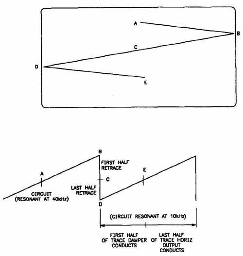
FIG. 12. One scan line and one retrace sequence.
Horizontal Scanning
The horizontal output circuit is resonant (can be tuned) to 10 kHz. However, in order to rapidly retrace (move back to the left side of the television’s screen) when the end of a scan line is reached, other components are added to the circuit so that the circuit is resonant at 40 kHz. These components are the damper diodes, the deflection yoke coil and capacitors, and the timing capacitors. A simplified horizontal output circuit with the deflection yoke connected is shown in FIG. 11.
In older televisions, the damper diode was external to the transistor. The damper diode is connected from the horizontal output transistor’s emitter to its collector. The deflection yoke coil is connected to the collector of the horizontal output transistor. The return capacitors are in series with the yoke to ground. For efficiency, the timing capacitor is parallel with the damper diode and the horizontal output transistor. This structure keeps the voltage discharge smaller and linear during a scan sequence—less than the capacitor’s total voltage.
FIG. 12 shows one scan line and one retrace sequence. The retrace requires a pulse of 10 kHz. The scan requires a pulse 40 kHz. In order to produce one scan cycle, the voltage must vary from 10 kHz to 40 kHz in an orderly, timed manner.
The scan takes exactly 51 msec. The retrace takes exactly 12.5 msec. In order for the scan to take place in 51 msec, the resonant frequency must be 40 kHz. The retrace requires 10 kHz.
For example, to begin the scan and move the electron beams from the center of the screen to the right side of the screen (A to B in the diagram), there must be a linear increase in magnetic energy on the right side of the screen to attract the electron beams. Therefore, the current in the deflection yoke is increased on the right side, which causes a magnetic field to build up around the right side of the deflection yoke. The magnetic field then attracts the electron beam to the right side of the screen.
When the resonant frequency increases to 40 kHz, the magnetic field around the yoke drops and the magnetic field collapses. At the same time, the current in the deflection yoke starts to increase on the left side, which causes the rapid magnetic field buildup on the left side of the screen. This causes the electron beams to return to the center (B to C) then deflect to the left (C to D). Finally, when the magnetic field on the left collapses, and the field starts to increase on the right side, the beams return to center (D to F) and deflect to the right again. FIG. l3shows the shape of a horizontal waveform.
Triggering a Scan/Retrace Sequence
Refer to the DATASHEET schematic for the television you are troubleshooting for the type of triggering device used in the chassis and the voltage values to expect when testing the inputs and outputs.

FIG. 13. A horizontal waveform.
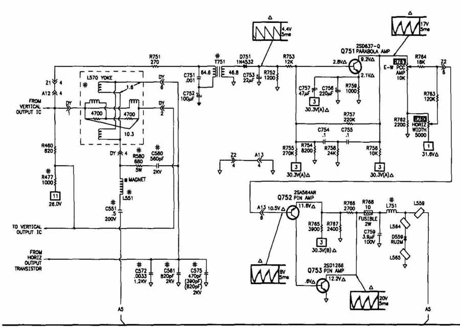
FIG. 14. A pincushion circuit.
A damper diode acts a switch that causes the transfer of current from the yoke to the capacitor, and causes the scan on the left side of the screen. The horizontal output transistor acts as a switch that causes the transfer of current from the capacitor to the yoke, and causes the scan on the right side of the screen.
An SCR (silicon control rectifier) also can be used to trigger a scan/retrace sequence. The SCR is a switching component that is turned on by a signal pulse. When voltage reverses in polarity or drops significantly, the SCR turns off. When it receives another signal pulse, it turns on again. There usually are two SCRs in a horizontal output circuit. One is used to trigger a scan; the other is used to trigger retrace.
Pincushion Correction Circuit
The pincushion correction circuit, shown in FIG. 14, prevents a distortion called pincushioning, shown in FIG. 15, where the picture appears to pull in at the center and out at the corners. The pincushion circuit increases the voltage to the mid-screen section of the yoke to compensate for the voltage reduction that caused the distortion.
Troubleshooting a Horizontal Output Circuit
If the horizontal output circuit is faulty, the symptoms can vary. If the television is totally inoperative (no sound or picture), the scan-derived power supply from the horizontal output circuit might have a shorted diode. Also, the boost circuit might be bad. Refer to Section 4, Troubleshooting Power Supplies, and Section 8, Troubleshooting High-Voltage Circuits, for more information on the scan derived power supply.
If the focus is bad, the picture is dim, the picture brightness is not right, or you see blooming on the screen, there is probably an overloaded circuit. Also, you might hear a ringing sound associated with the picture problem.
If you see a picture width problem, or if the picture folds or weaves, the source is probably a drop in the voltage pulses to the deflection yoke coil. If you see the keystone effect where the picture is narrower in one direction than the other, there is probably a short in a deflection coil.
If you turn on the television and the B÷ fuse blows, check for a shorted horizontal output transistor or damper diode. A shorted transistor or diode will cause the fuse to open.

FIG. 15. Picture pincushioning.
Note: If the emitter collector junction measures low resistance when checking a horizontal output transistor, be aware of any internal components that may have a low resistance measurement, such as a damper diode or resistor.
Note: The best way to trouble shoot horizontal deflection is to inject a horizontal drive pulse into the base of the horizontal output transistor. Problems in the transistor, flyback or yoke can then be detected.
Note: Voltage on the collector of the horizontal output transistor can cause damage to many oscilloscopes and voltmeters, due to the high peak-to-peak RF waveform.
A shorted damper diode or SCR suggests that there may be a high B+ voltage condition. An overloaded circuit can cause shorts. If you replace a damper diode or SCR, make sure you use exact replacements. In newer televisions, the damper diode is part of the transistor.
When you begin troubleshooting, use an oscilloscope and test the input signal to make sure it is correct. If it is not, trace it back through the path of the horizontal oscillator, sync and drive processing circuits until you find the source of the problem. If the input signal is correct, test the output signals and the output voltage from the horizontal output circuit.

FIG. 16. Interlaced scanning.
Vertical Deflection Circuits
When one set of 262+ horizontal lines are scanned, the vertical retrace causes the electron beams to be deflected back to the top left of the screen. Then, the next set of 262+ horizontal lines are scanned. FIG. 16 shows interlaced scanning and the signals for retrace on the alternate fields.
In the figure, the first field starts at (1) and ends at (2). The second field starts at (3) and ends at (4). During the vertical retrace when the picture is blanked, the beam moves back to (1). Then, the cycle begins again.
Horizontal scanning occurs 15,750 times every second. Vertical scanning occurs 60 times every second. The vertical deflection circuit also supplies a blanking signal so that the CRT’s screen blanks during the vertical retrace. A problem with the vertical deflection circuits can cause the picture to roll vertically.
In newer televisions, the vertical deflection circuit may be one or two ICs. The main stages in the IC are the vertical oscillator and the vertical output circuits. However, there may be other support circuits around the main stages, such as an amplifier between the vertical oscillator and the vertical output circuits.
Vertical Oscillator
Vertical oscillators produce a signal that turns off the vertical output transistors. Turning off the vertical output transistors causes the magnetic field in the vertical deflection yoke to collapse. The result is a retrace to the top of the screen. During the retrace, a blanking signal is sent to the vertical output circuits to turn off the scan and blank the screen.
The vertical oscillator operates at 60 Hz and is controlled by the sync pulses it receives from the sync separator. The vertical oscillator is always on, running at a slightly lower frequency than the sync signal from the sync separator. When the sync signal is input, the transistors conduct the signals. When the signal is discharged, the frequency drops and once again the oscillator is running at a lower frequency than the sync signal. This pattern of conduction and discharge creates a sawtooth waveform, like the one shown in FIG. 17. Also, since the vertical scan occurs at a much slower rate than the horizontal scan, pulses are sent out between each vertical scan/retrace cycle to keep the horizontal oscillator synchronized with the vertical retrace.
Note: In some televisions, the vertical oscillator is part of a countdown circuit of a horizontal oscillator normally internal to an IC.

FIG. 17. A sawtooth waveform.
The purpose of the vertical scanning waveform is to trigger the vertical oscillator, to blank the screen during retrace, to keep the horizontal scanning in sync during vertical retrace, and to make sure that alternate fields are interlaced.
Output from the vertical oscillator is a linear signal of 1V to 2V. The output is a modified sawtooth scan signal, shown in Figure 18 which is sent through an amplifier to the vertical output circuit. The amplitude of the sawtooth signal corresponds to the vertical size of the picture screen. The amplifier receives feed back from the vertical deflection yoke and adjusts the signal as needed. The signal cannot be linear if the sawtooth waveform is not linear. If the signal is not linear, the picture is scanned at an uneven rate and will be distorted.
Several types of oscillators can be used in the vertical circuits, such as:
1. Countdown circuit.
2. Sawtooth generator.
The vertical timing circuit, like the countdown circuit shown in FIG. 19, contains several flip-flop circuits that correctly divide the horizontal pulse, and “count down” from the horizontal rate to the vertical rate. The purpose of the timing circuit is to cause the capacitor to discharge at the right time to trigger the vertical retrace. Refer to the DATASHEET schematic for the correct input and output values for the television you are servicing.
If you suspect that the timing circuit is faulty, check the supply voltages and the feedback, as well as the components and connections around the IC. Also, you can temporarily replace the IC with one that you know is working properly. If the normal operation resumes, the IC is defective.

FIG. 18. A modified sawtooth waveform.

FIG. 19. A vertical countdown circuit.
Feedback in Vertical Circuits
When a picture is not linear, the top or bottom will appear stretched. The vertical circuits use feedback extensively to adjust a signal to more or less linear conduction. This maintains picture linearity and corrects picture distortions.
During linearity correction, a sample of the sawtooth signal is fed back to the amplifier. The sample is the opposite polarity of the nonlinear signal; thus, the nonlinearity is canceled out. Feedback also is used to “round off” the peaks in sawtooth signals.
Pincushion Circuit
Some televisions have a vertical pincushion circuit that prevents uneven vertical deflection, as shown in FIG. 20. When the vertical deflection is uneven, the picture appears to pull in toward the center at the top and bottom, and bow out on the sides. The horizontal pincushion effect causes the picture to pull in on the sides.
The vertical pincushion circuit controls the current flow to the yoke, which corrects the scan lines at the center, top and bottom of the screen. The correction voltage is taken from the flyback and sent to a transformer that is connected in series to the vertical yoke coils.

FIG. 20. The pincushion effect.

FIG. 21. A vertical output circuit.

FIG. 22. Vertical output waveforms.
Vertical Output Circuit
The vertical output circuit, shown in FIG. 21, is a power amplifier that sup plies a vertical output waveform to deflect the electron beams to perform the vertical scan and retrace on the CRT’s screen. Because of the current in the circuit, the amplifier in most televisions is mounted on a heat sink. The output from the vertical output circuit is a peaked sawtooth, shown in FIG. 22. The vertical output signal is sent to the CAT’s vertical deflection yoke coils and is used during scanning. The peaked portion creates the blanking signal that blanks the screen during the vertical retrace.
The output circuit can be directly coupled to the deflection yoke. However, the output circuit can use a resistor, capacitor, transformer or transistor to couple to the deflection yoke.

FIG. 23. The horizontal bar due to loss of vertical sync.
Troubleshooting the Vertical Deflection Circuits
When you troubleshoot the vertical deflection circuits, use an oscilloscope to look at the waveforms of the signals. Use a DMM to check the input and output voltages.
If the vertical stages are not working properly, the most common symptom is a horizontal white line on the screen and vertical distortion or intermittent vertical scanning. If a horizontal line appears, like the one shown in FIG. 23, and nothing else, turn off the television or turn down the brightness because the CRT can be damaged. If the vertical sweep fails on newer sets, they may blank the raster to prevent CRT damage. In this case the horizontal white line will not appear on the screen unless the master screen control on the horizontal output transformer is adjusted.
With picture problems that are not severe, such as distortion, line pairing or line splitting, or a short picture, use the vertical controls to adjust the picture:
1. Use the vertical height control to adjust the picture height.
2. Use the vertical hold for sync problems. Some television sets have eliminated the need for a vertical hold control.

FIG. 24. Keystoning.
Note: If the vertical height control does not adjust the height correctly, check all electrolytics in the vertical circuits and capacitors in the feedback circuit.
If the control does not adjust the picture properly, look for leaking or open di odes, capacitors, or transistors. A worn potentiometer also can cause a vertical picture problem. In the case of constant line pairing or line splitting, also check the sync separator. If the problem is intermittent, check the high-voltage stages. You could be seeing the results of a voltage discharge or arcing.
If the bottom part of the picture appears to be correct and the top is not, or the other way around, check for faulty push-pull transistors used in the vertical output circuit, or for a faulty capacitor. Disconnect and check the transistors and capacitors.
Distortion also can indicate a linearity problem. A distortion such as keystoning—the picture is smaller on one side than the other, as shown in FIG. 24—can be caused by a defective deflection yoke, as well as incorrect control does not signals from the vertical deflection circuits. However, when the picture spreads at the top or bottom, and compresses at the opposite end, there is probably linearity problem. FIG. 36 shows waveforms that are linear and others that are not.
When the picture rolls, use the vertical hold control to adjust the picture. If the control does not adjust the picture correctly, use an oscilloscope to check the signals into and out of the vertical oscillator. Also, check the sync separator because the vertical oscillator may not oscillate unless it receives sync signals.
If the vertical oscillator, the sync separator and all components connected to the two circuits are operating correctly, and all connections are sound, check the vertical drive circuits and yoke.
If the sync separator does not correctly separate the signals, there may be horizontal signals or noise mixed in with the vertical signals. In this case, check the sync separator and sync filter circuits. Then, check the circuits, components and connections in the horizontal sync circuits.
If the vertical deflection IC has been shorted, the supply voltages will probably be lower that usual. If the IC is open, the supply voltages will probably be higher than usual. If the IC output is lower than expected and the supply voltages are the expected values, check the components, especially the external bias components and connections around the IC. If the components and connections are operating properly, the IC is probably bad.
Quiz
1. What is the purpose of the peak or spike of the vertical output wave form?
2. What is the proper name of the horizontal oscillator correction circuit?
3. Why does the vertical scan start at the top left for the first field of scan, and the top center for the second field of scan?
4. The horizontal drive signal drives what circuit?
5. What component deflects the electron beams in the CRT?
Key
1. Vertical blanking.
2. APC (automatic phase control) or AFC (automatic frequency control).
3. It allows for interlacing.
4. The horizontal output circuit.
5. The deflection yoke.