A television’s tuner stage, shown in FIG. 1, selects one channel from all of the signals received by the antenna. Each channel consists of an RF frequency that contains two carriers: the FM sound carrier and the AM video carrier. The tuner circuit adjusts the level of the RF signal and converts it into an IF signal. So, the tuner circuit has one input, the RF frequency, and one output, the IF signal, even though there are two carriers in the RF frequency.
Each of the television stations in a geographic area transmit on a specific frequency. In order to select one signal from all of the possible signals and have all of the other stages in the chassis recognize the selected signal without having to constantly retune, televisions use a tuning method called heterodyning.
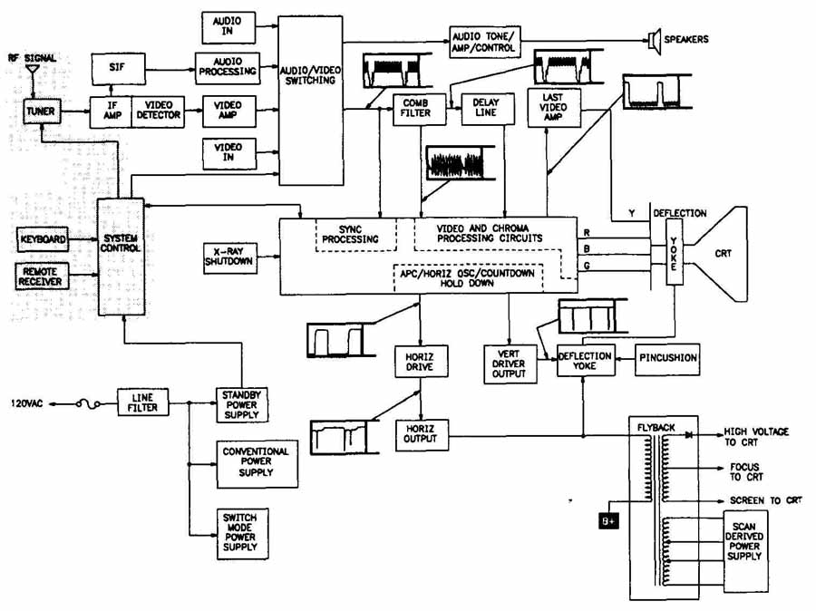
FIG. 1. The tuner stage (shaded).
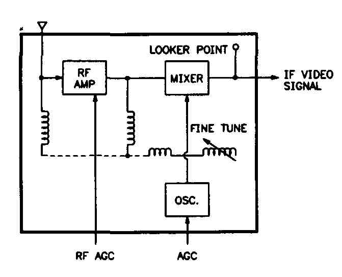
FIG. 2. A “Generic” tuner circuit.
In heterodyning, when you select a channel, the RF amplifier is tuned to that frequency. The RE amplifier amplifies the signal and outputs it to the mixer stage. Then, the oscillator outputs its signal reference to the mixer. These two input signals are mixed so that the output signal from the mixer is the difference between the two signals, or the intermediate frequency (IF). All of the later stages in the chassis are permanently tuned to the IE so that they do not have to be retuned each time you select a new channel.
There are two types of tuner circuits:
1. A “discrete” tuner is composed of individual components as part of the main board. If a discrete tuner is not working correctly, you can test the components, locate the one that is faulty, and repair it.
2. A modular tuner is a replaceable unit that is easier to replace than try to repair when it is faulty.
FIG. 2 shows a block diagram for a “generic” tuner circuit.
Manufacturers have developed several types of tuners, including varactor (variable capacitance diode) and frequency synthesis tuners. However, all tuners, including the older mechanical tuners and hybrid tuners, have three main tuner stages: RF amplifier, oscillator and mixer.
RF Amplifier
The RF amplifier:
1. Provides frequency selectivity.
2. Improves the signal-to-noise-ratio.
3. Prevents the radiation from the oscillator from leaking back to the antenna.
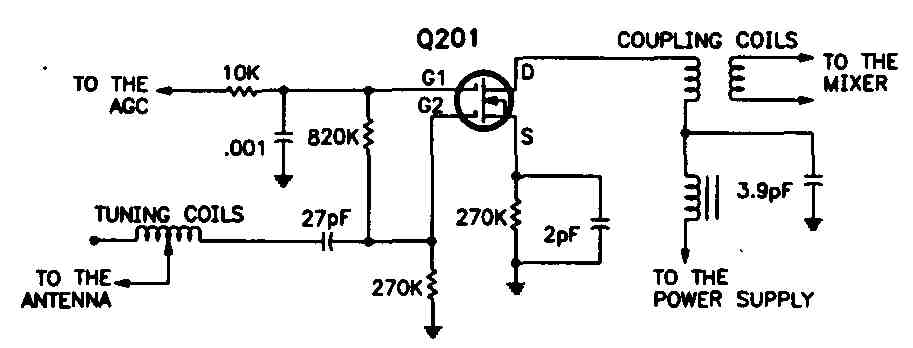
The RF amplifier stage, shown in FIG. 3, selects one RF signal from all of the signals being received by the antenna, amplifies it, and outputs it to the mixer. The AGC (automatic gain control) is connected to the RF amplifier and controls the gain of the amplifier by offsetting variations in the carrier signals. The RF amplifier can be a transistor or a FET (field effect transistor).
The television’s antenna is part of the RF amplifier circuit. The RF amplifier blocks the signal from the oscillator from leaking back to the antenna. Signal leaking can cause picture interference.
Oscillator
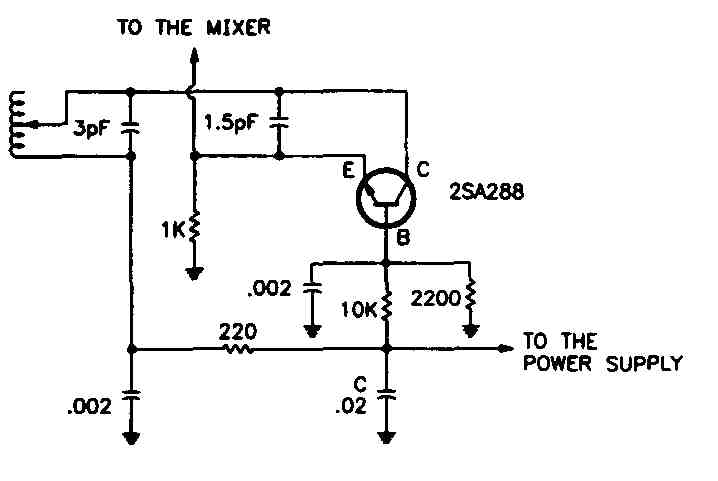
The oscillator stage, like the one shown in FIG. 4, outputs an unmodulated reference signal to the mixer that tracks the desired RF signal at a fixed, offset frequency. The frequency of the reference signal is manufacturer dependent.
Also, tuners have an AFT (automatic fine tuning) circuit connected to the oscillator. The AFT shifts the oscillator frequency as needed to keep the signal in phase with the selected channel frequency. Older televisions have manual fine tuning controls that keep the signal in phase with the channel frequency.
Mixer
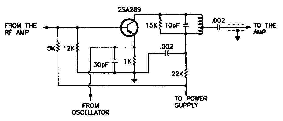
The mixer stage, like the one in FIG. 5, inputs the RF signal and the oscillator signal, mixes the signals, strips out the extraneous signals from the original RF signal and oscillator signal, and produces the IF signal. The conversion must be performed without distorting the incoming signal. Mixers are sometimes called frequency converters, frequency translators or heterodyne detectors.
The output from the mixer is an IF signal, as shown in FIG. 6. The frequencies represented in the signal are constant so that the signal can be used in later stages in the chassis:
1. 39.75 MHz—The adjacent channel’s video carrier.
2. 41.25 MHz—Audio carrier.
3. 41.67 to 42.67 MHz—Color carrier.
4. 45.75 MHz—Video carrier.
5. 47.25 MHz—Adjacent channel’s audio carrier.
Tuner Types
Listed below are only three of the types of tuners you will see. The design of most tuners are dependent on the individual manufacturers:
1. A varactor tuner is a diode that acts like a variable capacitor when the diode is biased by a variable voltage supply. The capacitance can be changed over a large range of frequencies by inputting a control voltage from the regulated low-voltage power supply.
When a channel is selected, a pre-selected voltage for that channel is applied to the diode. This causes the diode to align with the selected frequency. When you fine tune the frequency, the applied voltage is slightly adjusted using a potentiometer on older sets, or by an AFT correction voltage on newer sets, until the diode is completely aligned with the frequency.
2. A reactance tuner consists of coils and a capacitor. Each coil is assigned to a tuner frequency. The coils are connected with a multiple contact switch or a series of diodes used as switches. When a new channel is selected, the switch contacts another coil and the channel changes.
3. A frequency synthesis (FS) tuner, also known as digital tuning or quartz tuning, provides up to 127 channels and all of the UHF frequency band. The FS circuit is an IC that contains additional stages such as a phase locked loop (PLL), step generator, a frequency band switch decoder, an AFT, digital sync, and a presence decoder. Refer to the schematic for details about the FS tuner.
Troubleshooting Tuner Circuits
The quickest way to see if the tuner circuits are faulty is to inject an IF signal at the tuner’s IF output. If the picture returns to normal, check AFT, B+ supplies, and switching circuits. If they check out okay, replace the tuner.
If the picture does not return to normal, check the IF amplifier, the video processing stages and the power supplies. A defective power supply can cause the channel frequencies to “drift,” which results in poor fine tuning and poor reception.
Picture problems can be caused by faulty tuners, as well as other stages in the chassis. The components in the tuners are very critical in value and placement in the circuit. Extreme care must be used when working in the tuner as mis alignment can occur, which can result in a very poor or no picture. With any picture problem, if you determine that the tuner is faulty, it is many times less costly to replace the tuner than to try to repair it, plus this will result in a much better picture.
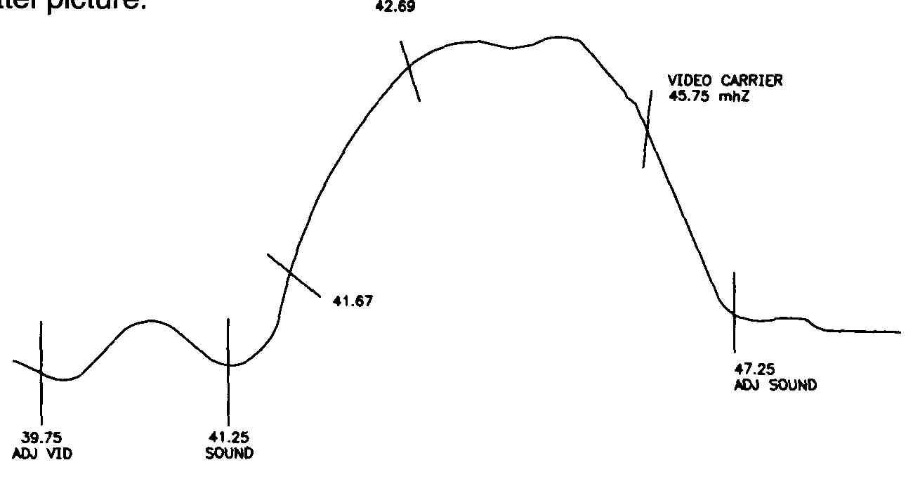
FIG. 6. An IF signal waveform.
Drifting
If the television appears to have drifting frequencies and is not holding one channel, the problem may be in the power supply to the tuner:
1. Disconnect the AFT (automatic fine tuning) circuit.
2. Check the inputs to and outputs from all components (or pins in an IC) that are in the supply voltage path.
3. If the supply voltage varies, the supply voltage circuit may be faulty.
4. If the supply voltage is stable, the tuner may be faulty.
Strong Raster with No Picture or Sound
If you see a strong raster pattern on the screen with no picture, and have faint or no sound, the tuner’s mixer might be faulty. This condition also is caused by a faulty IF amplifier or a video processing circuit. If there is no snow, the mixer is probably faulty because it generates most of the raster snow (noise) pattern.
Strong Raster with Weak Picture and Sound
If you see a strong scanning pattern and very weak picture, and hear very faint sound, the RF amplifier or the antenna connection might be faulty. This condition is often accompanied by a hissing sound. If you adjust the contrast, the snow should increase. If you adjust the volume, the hissing sound should in crease. This indicates that the mixer and the following stages are operating. Therefore, the RF amplifier is probably faulty.
If the RF amplifier is working correctly, check the AFT, the IF amplifier, and the video circuits.
Weak Raster with Weak Picture and Sound
If you see a weak scanning pattern and very weak picture, the mixer is probably faulty. You also might hear faint sound. This condition also is caused by a faulty IF amplifier.
Weak Raster with No Picture or Sound
It you see a very weak scanning pattern and no picture, or do not hear sound, the oscillator might be faulty. This condition also is caused by a faulty IF amplifier.
No Raster, and No Picture or Sound
If the mixer circuit fails, or if the regulated B+ power supply is faulty, you may not see a scanning pattern (snow), and the sound and picture can range from none to very weak. In this case, inject an IF signal at the mixer’s output. If the picture returns to normal, and the B+ power supply is working correctly, the mixer is probably the source of the problem.
Replacing a Modular Tuner
When a modular tuner is faulty—you see problems with color, video or sound, or experience intermittent problems—check all of the soldered connections around the tuner shield. Then, if you need to replace a modular tuner, order an exact replacement for the tuner circuit and follow these steps to remove the old tuner and install the new one:
1. Unplug the chassis from the AC power source.
2. Disconnect the antenna lead and the IF circuit lead.
3. Remove solder from any soldered connections. Make sure you re move any remaining solder from the connections so that the connections are clean for the replacement.
4. Unbolt the circuit from the chassis if it is attached by bolts.
5. Insert the new tuner.
6. Complete any connections according to the instructions that may be included with the replacement.
Quiz
1. How many inputs and outputs does the tuner circuit have if there are two carriers in the RF frequency?
2. Describe the two types of tuner circuits.
3. What is the purpose of the AF amplifier?
4. What is the purpose of the automatic fine tuning (AFT) circuit?
5. Describe the differences between a varactor tuner (a), a reactance tuner (b), and a frequency synthese (FS) tuner (c).
Key
1. One of each: The RF frequency (input) and the IF signal (output).
2. The discrete tuner is made of individual components as part of the main board, and the modular tuner is an individual replaceable unit.
3. It provides frequency selectivity, improves the signal-to-noise ratio, and prevent oscillator radiation from leaking into the antenna.
4. It shifts the oscillator frequency as needed to keep the signal in phase with the selected channel frequency.
5a. A varactor tuner is a diode that acts like a variable capacitor when the diode is biased by a variable voltage supply;
5b. A reactance tuner consists of coils and a capacitor. When a new channel is selected, the switch contacts another coils and the channel changes.
5c. A frequency synthesis (FS) tuner is an IC that contains additional stages. It provides up to 127 channels and all of the UHF frequency band.
