DAVIS UPDATES HEIL
I’d LIKE TO offer a few bits of information I've gathered about building the Heil type tweeter since my article appeared in TAA 2/787, p.15.
First, the easiest way to make the diaphragm is to etch the foil pattern with ferric chloride (standard circuit board etchant). I've been able to make several diaphragms in just one evening with this technique and have saved myself many hours of nervous frustration.
To etch the diaphragm, glue a sufficiently large piece of foil, with the two sides folded over for reinforcement, onto the .5 mil polyethylene. Protect what will be the short (horizontal) lines of the pattern by burnishing on etch resist such as the Datak Dry Etch transfers. Protect the long lines of the pattern with drafting tape of the desired width.
Before etching the foil, add the top and bottom reinforcement strips, covering them and the side strips with a layer of rubber cement so they will not be at tacked by the etchant. Then lay the foil and plastic in the etchant to remove all foil not protected by tape, polyethylene, or rubber cement. When the etching is complete, remove the tape from the long runs but don't bother trying to remove the transfers. Glue on a top layer of polyethylene to complete the diaphragm.
You must etch the diaphragm in a diluted etchant solution, since full strength ferric chloride will actually harden the plastic from the intense heat of its reaction with the aluminum, and bury the diaphragm in a flurry of bubbles. If the etchant is too weak, the water will eventually seep in under the tape and attack the pattern. Adjust the solution to thoroughly etch the foil in about one half hour; you'll find you need somewhere around one-quarter strength.
I've made a number of diaphragms with this technique, and found it especially easy to take advantage of the 0.1" spacing between IC pads on the Datak ER 14 sheet. By using every other pad and using 0.100'' drafting tape, a 2'' x 8'' diaphragm can be laid out in less than an hour. The diaphragm will be approximately two inches square when folded and will require a %¢'' magnet gap, making it midway in size between the full size and mini versions described in my article. This smaller magnet gap allows high performance with fewer magnets, and the diaphragm is still large enough to be crossed over at 1500-2000Hz.
The mini-Heil can easily be laid out using half these dimensions, but the %"' tape does not always flawlessly protect the foil. The etchant will occasionally work its way under this narrow tape and etch very fine cracks across the foil to destroy the current path. Two out of six that I etched failed for this reason, but I am confident a little experimentation will give a better yield for the mini diaphragm.
Second, I've found things go much smoother if one builds the tweeter with a removable front grid. Several beads of silicon glue can then be run along the magnet structure inside the gap to keep the diaphragm securely positioned. This way the diaphragm has no chance to rattle against the pole pieces, and initially establishing the individual pleat spacing is much easier. Use silicon glue to hold together the strips that will form the front grid, and lay this front pole piece in place after the diaphragm is secured to the magnets and rear pole pieces. Silicon glue and a simple wood or aluminum frame will keep the assembly rigid.
Third, I'd like to stress again that there are many good ways to build a magnet structure; I stress this point because the high cost of magnets and metal may force the experimenter to improvise in order to keep down expenses.
For quick, low-cost experimenting, a surprising amount can be done with a little imagination, salvaged magnets from defective speakers, and odd sizes of hardware.
Since the price of 2" x 5"' x 3/8'' solid bar magnets puts the total cost for a stereo pair of Heils at over $300, it is absolutely necessary to use a number of smaller magnets glued together.
However, I'd hesitate recommending the extreme Mike Hamill suggest in his letter (TAA 4/78, p. 50), since gluing 384 repelling magnets could be a messy, sticky, and difficult job; but I certainly applaud his resourcefulness. The 1 7/8 x 7/8 x 3/8'' magnets from Edmund are probably still the best way to go if you have no other choice, but the least expensive course is to salvage magnets from defective speakers and design the magnet structure and diaphragm around your magnets. This approach is especially worthwhile if your goal is to get a Heil up and going for an inexpensive audition.
And fourth, I'm curious to know if anyone has tried constructing the mini Heil, which is not, as Hamill suggested, a laborious form of gilding the lily. The commercial Heil unit, as I pointed out in my article, is non-directional in the horizontal plane, this of course is because the diaphragm opening is a ¾” slit. However, the Heil is extremely directional in the vertical plane, since the opening is near 5'--and anyone who has listened to this speaker is immediately aware of the enormous difference between listening on the tweeter's horizontal plane and listening out of this plane.
Even more startling is comparing a directional Heil with an entirely non directional one. The intense brilliance of the directional Heil completely disappears in a non-directional version, and is replaced by a subtlety and realism which are at first hearing rather unimpressive. Amplifier hiss is still there and all high frequencies are for a fact being reproduced, but the speakers seem to have an altogether different character. I hope other readers will experiment more with the non-directional configuration of Heil-type tweeters, since the difference is, at the very least, quite interesting.
I'd also like to encourage readers to attempt building a Heil of any size, especially if they have spare magnets from scrapped speakers. Of course, being able to etch a diaphragm, rather than having to perform microsurgery on an uncooperative slice of aluminum, greatly simplifies the project. This amateur's version is quite amazing in terms of quality; and controlling directionality, efficiency (basically, the number of magnets used), cost (size and number of magnets, and physical dimensions, while still maintaining low distortion and flat response, can be a rather exciting freedom for the audio amateur.
NEIL DAVIS; Annandale, VA 22003
A 3dB LADDER
THIS CIRCUIT PRODUCES a series of reference voltages separated by 3dB increments. Such a circuit is useful, for example, as part of a digital VU or power level meter, using LEDs for display.
If one attempts to produce these voltages by a straight divider string, the resistors take on oddball values which make it hard to implement accurately.
My circuit uses a variation on the familiar ''R-2R'' ladder network commonly found in D-A converters. ''R'' represents any convenient value of resistance, and the other resistors in the ladder are scaled accordingly.
The diagram shows exactly calculated ratios, along with currents in mA through the ladder for R =1k ohm . Any number of steps or voltages may be produced by simply including extra resistors within the ladder in the pattern shown. If one chooses 5% resistors, then 1k, 8.2k and 2.4k are a logical choice for the ladder resistors. These values are within 0.5% of the calculated ratios, insuring good accuracy, especially if the resistors are selected or checked. If extreme accuracy is required, then ...
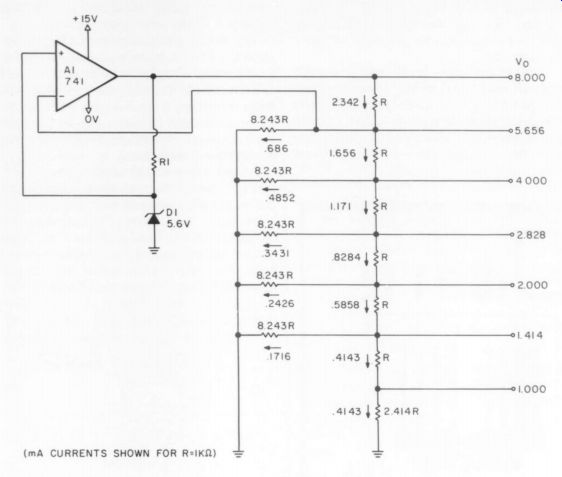
----- (mA CURRENTS SHOWN FOR R= 1 K ohm)
1% resistors may be used with values 1k, 8.25k and 2.43k. For general use, an op amp and zener diode produce a regulated voltage source. The voltage at the top of the ladder will be 1.41 times the zener voltage. Of course one may connect the ladder to another regulated voltage if one is available.
RICHARD K. BRUSH; Salt Lake City, UT 84106
HEADSHELL LEVELING:
SME 3009 III WHEN SETTING UP A TONEARM, one of the most difficult adjustments is setting the top of the headshell parallel to thé record surface. Most manufacturers call for this adjustment to be made by eye, which is not very precise: because the headshell is so small, one can err greatly in guessing whether or not the headshell is parallel to the record surface. Fortunately an objective way to make the adjustment is not difficult to invent and implement.
A spirit level provides a simple way to determine if the top of the headshell is level in playing position. Use the following procedure with a small spirit level encased in a block of plastic 3"'x1"'x
1) First set up the arm completely according to the manufacturer's instructions. Then, with the arm in playing position near the outside of a record, measure the height of the front of the headshell above the turntable surface or some other convenient, fixed surface (not the record surface.) Record this measurement for later reference.
2) In the following step you will place the spirit level on the headshell, so take precautions to prevent damage to the stylus: either remove the stylus assembly or install a sturdy, rigid guard now.
Remove the record and mat (unless it is flat) from the turntable platter. Next, rest the cartridge on some rigid shims of solid metal or plastic, adjusting its height to equal the playing height measured in step 1 (see Fig. 1). It is important that the platform of shims be both level and firm to properly support the cartridge.
3) Hold the spirit level (which should be small and light) to the smooth upper surface of the headshell. If it indicates that the headshell is level, all is OK (if your turntable is level!). Otherwise, use whatever adjustments the tonearm manufacturer provides (arm height, etc.) to level the headshell, using the spirit level as your unambiguous guide.
4) Once the headshell is level, remove the spirit level and return everything to normal playing condition. Re-check the arm height, using the same method used in step 1. If the new height is within 1/16'' of the old height measured in step 1, all is well. This 1s what you should find if your initial height adjustment wasn't too far off. Otherwise you will have to keep repeating steps 2 and 3 until agreement is reached between the arm height you measure before and after making levelness adjustments.
I used this method to set up my SME 3009 III tone arm, and discovered Shure unknowingly had a quality control problem with the carrying arm. I found I could not set the headshell parallel to the record surface unless I raised the arm so high that the stylus could no longer touch the record surface. This problem
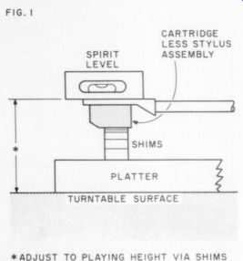
------------ FIG. 1 -- ADJUST TO PLAYING HEIGHT VIA SHIMS
was not apparent when setting up the arm according to SME's instruction, which give less precise results than my method. Of the three carrying arms I have examined, two were defective in this manner; one of them was later given a chiropractic adjustment by Shure, and is now OK.
The trouble is a carrying arm can be within the tolerances specified by SME and still be sufficiently misshapen to cause the problem I mentioned.
Shure are now aware of this: they agree that my method of adjusting arm levelness is valid and superior and that their arm should allow such precise adjustment. I suggest any 744 reader who owns a series III arm and discovers it is also defective should write to Shure [222 Hartrey Ave., Evanston IL 60204]. My own correspondence with them was rather lengthy since I was the first to detect the difficulty, but they were very helpful once they recognized the problem of loose tolerances.
Whether or not all this is worthwhile depends on the audibility of cartridge misalignment. I have found even a small error can have pronounced effects on sibilance and the proper reproduction of depth.
BRIAN CLARK; Sunderland, MA 01375 USA.
ZENERS UNMYSTIFIED
MANY PUBLICATIONS give instructions for selecting the components in a given simple voltage stabilizer detailed in a power supply schematic. These methods work, but I cannot seem to remember them, and they usually ignore the fact that you must choose from a rather small number of zener power ratings.
My method selects the zener's power rating first so that the resulting stabilizer will have the maximum current output that that zener can tolerate. The only simplifying assumption I will make is that you want the zener to be safe with the load disconnected.
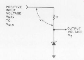
First find the voltage drops across the resistor R. Allow for the input voltage to vary between V a, and Visas illustrated in the figure. The voltage drops are:
V Rmin - Vrms - Vz
and
V_Rmin -- Wisndia - V;
where V; is the desired zener voltage.
Now you can choose the zener's ...
--------------
POSITIVE INPUT VOLTAGE Vmax T0 VMIN OUTPUT VOLTAGE Vz
...power rating. Basically it is the product of the voltage of the zener and the current required, but two adjustments are needed. First allow for the fact that you'll have to use standard value resistors by using a current 10% larger than you'll need.
The second adjustment will allow delivery of the maximum current under minimum voltage input. The power of the zener must be at least the zener voltage times the maximum current increased by the ratio of the voltage drops:
(eqn 1)
Select the next larger available zener power rating.
Next the resistor is the product of the larger voltage drop and the zener voltage, divided by the zener power rating:
(2)
You will find this important formula easy to remember if you note that if the zener 1s one watt, the resistor is just the product of the voltages. Compute the resistor's power rating by the usual V^2/R, using V gma for the voltage:
(3)
Use the next larger available resistance and wattage.
As a check on the result, compute the maximum current your circuit can put out by:
(4)
As an example, suppose you have need of 12 volts at a current of 20 milliamperes and you have a supply that can vary between 15 and 20 volts. The two voltage drops are thus 3 and 8 volts.
By (1) the zener power is:
Pz = [(8)(12)(0.022)] / 3 = 0.71 watts, so you'll need a one watt zener.
By (2) the resistor is:
By (3) the power rating is:
2 P, = 5 _ 96 so you'll use a 100 ohm, 1 watt resistor.
By (4) the maximum current is:
- 3 -30Ma.
0.67 watts, Lx For a negative supply, reverse the zener and do the same computations ignoring minus signs.
DAVID CARLSTROM; Huntington Woods MI 48070
----
Also see:
Kit Report: The Integrex Dolby Noise Reducer, by Fred M. Gloeckler, Jr.
The Williamson 40/40, Power Amplifier--Return of an improved favorite after a decade