THE BORBELY PREAMP: PART 2
In TAA 4/85, Mr. Borbely discussed the RIAA-1 and RIAA-2 sections of his preamp. This time, he describes the line amp, tape buffer and power supplies. Figure 19, rerun from Part I, shows the pin-outs for the various devices used in his design.
------------
EXCEPT FOR THE FEEDBACK network, the line amp (Fig. 20) is the same as the second stage of the RIAA amp. The line amp has a flat gain of 20dB. I included a balance adjustment in the feedback network, using ganged potentiometers for the two channels. The total adjustment range for each channel is approximately 4dB, with the gain going from 17.6 dB to 21.6 dB. If your balance requirements are greater than 4dB, you can change the feedback network as shown in Fig. 21. The adjustment range with this circuit is approximately 8dB. Which ever schematic you use, one thing is very important: only the highest quality potentiometer is good enough for this spot. It should be a low-noise type with very good contact between the wiper and the resistive layer. A conductive plastic or cermet pot is preferable.
As you can see, I did not include regulators on the line amp board (Figs. 22 and 23). My idea was to run it from as high a supply voltage as possible to increase overload capability and reduce distortion. If you prefer to supply regulated voltage to this stage, you might consider using the second type of power supply board I propose, which has regulators on it.
Alternatively, you may use the second stage RIAA boards (RIAA-2) as line amps. As I mentioned earlier, the only difference between the RIAA-2 amp and the line amp is the feedback network, and you can easily configure the RIAA-2 board as a 20dB flat amplifier.
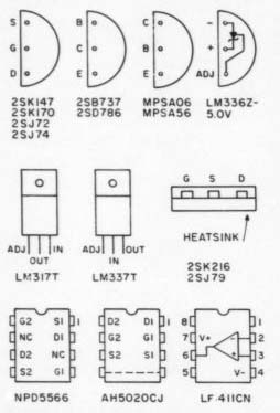
FIGURE 19: Pin-outs for the devices used in Mr. Borbely's design. These
are bottom views, except for the LM317/337.
Although the layout was designed for an input and output capacitor, none is really necessary when using the servo circuit. Again, I included an offset adjustment in the input stage (P1), and the setup procedure is the same as in RIAA-2. If you choose to run the amp in DC mode (this is also possible because of the low gain), you do not have to install the servo circuit at all. In this case, however, I recommend using the output capacitor. A 4.7 to 10 uF polypropylene cap is suitable here.
The output stage is the same as the one on the RIAA boards. Quiescent current should be adjusted to approximately 15mA, and a snap-on heat sink should be used on the MPSA transistors. If you wish to drive loads down to 60 0-ohm, you must change the output devices to Hitachi MOSFETs (2SK216/2Sj79s). Adjust quiescent current to about 20mA. With a 10uF cap at the output, the load should not be lower than a few kilo-ohms to avoid low-frequency losses.
If you use the line amp in DC mode without input and output capacitors, you must bypass C1 and C15 with jumpers. Connect the balance control with a twin-lead shielded cable with very low capacitance. Table 4 lists typical specifications for the line amp.
Tape Buffer Although you can build a minimalist preamp with the modules described thus far, our kind editor suggested that I include a tape buffer in the design. He noted that some tape machines act as nonlinear loads when switched off, feeding distortion into the top of the level control. As I was just looking at some high-quality unity-gain buffers for a four-way crossover, it was easy to adapt one of those to the task of tape buffering.
The buffer topology (Fig. 24) is the same as that of the RIAA amplifier's input stage, so a detailed description should not be necessary. Due to the unity gain, the buffer is all DC coupled, with an offset adjustment in the input stage. P1 should be a cermet trimpot for long-term stability. The input FETS are from Toshiba, but are different from those in the RIAA devices. The 2SK170/2Sj74 devices have less transconductance (gm) and a bit more noise than the 2SK147/2Sj72s. Consequently, they also cost less.
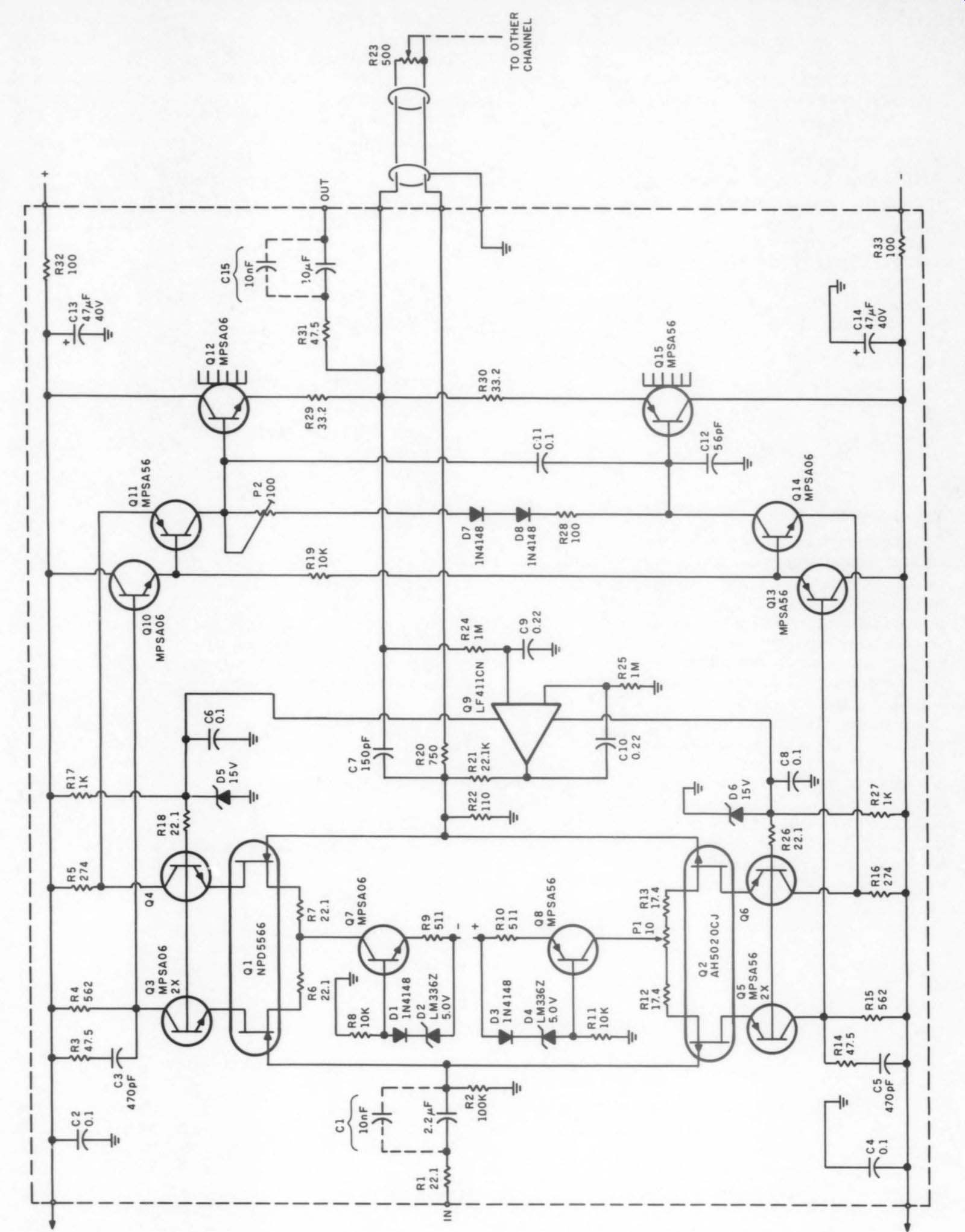
FIGURE 20: The line amplifier has a built-in active balance control.
The FETs come in four I_dss (drain current) groups covering a range of 1 to 20mA. You should not use the lowest group, Y (1 to 3mA), in this circuit. The second stage uses MPSA06/MPSAS56 bipolars, with un decoupled emitter resistors. The + 22V supply voltage can be taken from the line amplifier boards.
Figure 25 is the board layout for the tape buffer, and Fig. 26 is the stuffing guide. Typical specifications for the tape buffer are as follows:
Gain: Unity Frequency Response: -3dB at >10MHz Rise Time: 0 to +8V, 50nsec
THD: 4V RMS, same as measurement setup.
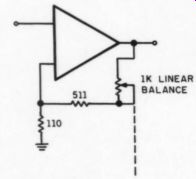
FIGURE 21: If your balance requirements are greater than 4dB, you can
use this balance control circuit, which has an adjustment range of approximately
8dB.
Power Supplies
To get the full potential out of the circuits presented so far, you must complement them with a high-quality power supply. Besides proper regulation, I find that two things improve sound quality: using separate supplies for the two channels and mounting the transformer(s) in a separate box.
The first improves channel separation, reduces intermodulation distortion and eliminates ground loops.
Putting the transformer in a separate box preserves all the low-noise capability of the circuit because there is no magnetically induced noise (hum) in the amplifier. You might solve the latter problem by shielding the trans former inside the preamp, but the separate box is a simpler and cheaper solution.
As I mentioned in the line amp section, I did not include regulators on the line amp board. This should not prevent you from using regulated supplies for the line amp, though. I propose two power supply solutions (Photo 4), one with and one without regulators for the line amps.
Power supply arrangement 1 is shown in Fig. 27. This is based on ...
--------------
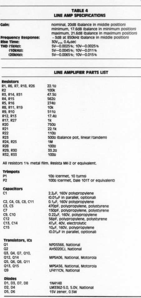
TABLE 4 LINE AMP
SPECIFICATIONS nominal, 20dB (balance in middle position) minimum, 17.6dB (balance in minimum position) maximum, 21.6dB (balance in maximum position)
-3dB at 850kHz (balance in middle position) 30V,.p, 0.4 usec 5V-0.0025 %; 10v-0.0025 % 5V-0.0045 %; 10v-0.011 % 5V-0.0065 %; 10v-0.015 %
----------------
LINE AMPLIFIER PARTS LIST
Resistors R1, R6, R7, R18, R26 R2 R3, R14, R31 R4, R15 RS, R16 R8, R11, R19 R9, R10 R12, R13 R17, R27 R20 R21 R22 R23 R24, R25 R28 R29, R30 R32, R33 22.10 100k 47.50 5620 2740 10k 5110 17.42 1k 7500 22.1k 1100 5000 (balance pot, linear/tandem) m™ 1000 33.20 1000 All resistors 1 % metal film. Resista MK-2 or equivalent.
c1 C2, C4, Cs, C8, C11 C3,C5 C7 C9, C10 C12 C13, C14 C15
Transistors, ICs 1 Q2 Q3, Q4, Q7, Q10, Q12, Q14 Q5, Q6, Q8, Q11 Q13, Q15 Q9 Diodes D1, D3, D7, D8 D2, D4 DS, D6 100 (cermet, 10 turns) 1000 (cermet, Dale 101T or equivalent) 2.24F, 160V polypropylene (0.014F in parallel, optional)
0.1 uF, 160V polypropylene 470pF, polypropylene, polystyrene 150pF, polypropylene, polystyrene
0.22uF, 160V, polypropylene S56pF, polypropylene, polystyrene 47uF, 40V, electrolytic 10 uF, 160V, polypropylene (0.014F in parallel, optional) NPD5566, National AH5020CJ, National MPSA06, National, Motorola MPSAS6, National, Motorola LF411CN, National 1N4148 LM3362-5.0, 5.0v, National 15V zener, 0.5W
----------------------
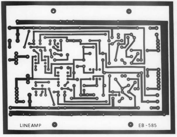
FIGURE 22: Circuit board layout for the line amplifier.
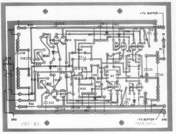
FIGURE 23: Stuffing guide for the line amplifier.
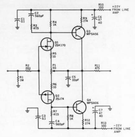
FIGURE 24: The topology of the optional tape buffer is the same as that
of the RIAA amplifier input stage.
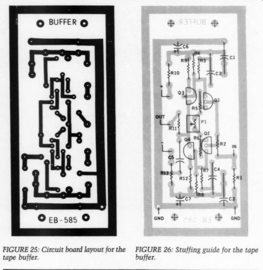
FIGURE 25-26
---------------

TAPE BUFFER
PARTS LIST
Resistors R1 Mm R2 2210 R3, R7, R11 47.50 RA, RS 1K RS, R6 100 RY, R12 2740 R1 1000 R10, R13 All resistors 1 % metal film. Resista MK-2 or equivalent.
Trimpot P1 500, (cermet, Dale 101T or equivalent) Capacitors
0.1 uF, 160V, polypropylene C2, CA 560pF, 160V, polypropylene, polystyrene C5 33pF, 160V, polypropylene, polystyrene 47uF, 40V, electrolytic 25K170, Toshiba 25J74, Toshiba MPSAS6, National, Motorola MPSAQ6, National, Motorola
----------------
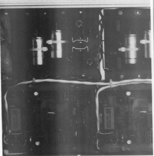
PHOTO 4: Two power supply boards supply the unregulated
voltage to the RIAA boards and the regulated + 24V to the line amps.
The six-pin LEMO (type 2B) connector for the transformer box is shown
in the upper right corner of the picture.
Note that the line amps shown on the left have a slightly different layout from the one described in the text: I added the optional 10nF caps in parallel with the input and output caps. The white cables are low-capacitance shielded cables connecting the balance pot to the line amp.
---------------------
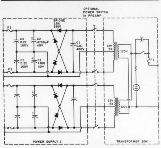
FIGURE 27: In power supply arrangement 1, keeping the transformer(s)
in a separate box, as always, will alleviate the hum problem.
... power supply board 1 (Figs. 28 and 29), which contains two independent supplies. You can use 2,200 to 4,700uF filter capacitors on the board.
(Note that the big filter caps should be strapped to the board with cable ties.) Although the higher value is recommended, you must remember that you are approaching capacitor values normally used in medium-size power amps with corresponding surge currents at switch-on. This requires a large value for the fuse (F1) on the transformer primary. I ended up using a 1A slow-blow fuse with a 220V primary, which you must double for 110V. This is, of course, much higher than that necessary for normal operation of the preamp. One way to avoid this would be to include a time-delay circuit, which connects a resistor in series with the caps to limit the surge current. However, for simplicity, I didn't include such a circuit in this design.
Two separate transformers are ...
---------------
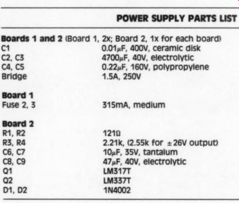
POWER SUPPLY PARTS LIST
Boards 1 and 2 (Board 1, 2x; Board 2, 1x for each board)
C1 0.014F, 400V, ceramic disk C2,C3 C4,C5 Bridge 1.5A, 250V Board 1 Fuse 2, 3 315SmA, medium Board 2 R1, R2 R3, R4 C6, C7 Cs, C9 1 LM317T Q2 LM337T D1, D2 1N4002 1210 47004F, 40V, electrolytic 0.22uF, 160V, polypropylene 2.21k, (2.55k for +26V output) 10 uF, 35V, tantalum 47,F, 40V, electrolytic
-----------------
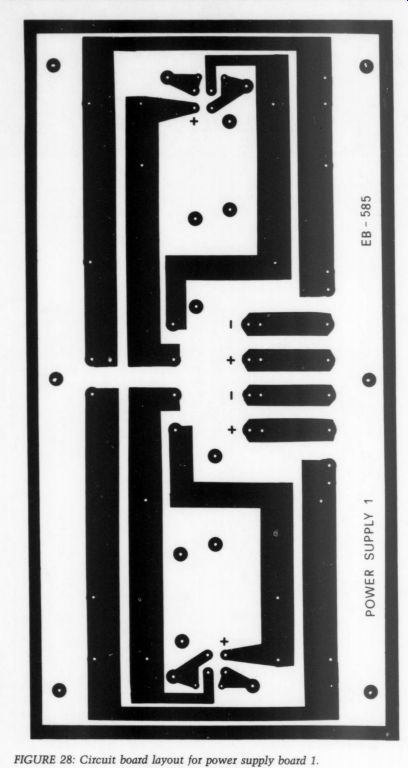
Fig. 28
... shown in Fig. 27, but there is no reason why a single transformer with two secondaries should not work. I used such a custom-made transform er in one of my prototypes. The secondary voltage should be 21 to 22V RMS, which will give you a no-load DC voltage of 29 to 31V. If you have problems finding this transformer or prefer to use a 2 x 24V one, you must modify all your regulators to produce a 26V output instead of +24V. This is to limit power dissipation in the regulators, especially those on the RIAA-2 boards.
Although the transformer box is supposed to be placed away from the preamp and it might not be convenient to turn on the preamp from this box, I indicated a power switch there.
If you prefer a power switch in the preamp itself, you need a four-pole device because you must switch both channels. You might also make other switching arrangements when needed.
The second power supply arrangement is shown in Fig. 30. This is based on power supply board 2 (Figs. 31 and 32), which supplies one channel of a stereo amp. You will need two of these boards. The rectifier/ filter is the same as on board 1, and the added regulator circuits are the same as the ones on the RIAA-2 boards.
Unregulated voltages for the RIAA stages are taken before the regulators, and the regulated + 24V outputs feed the line amps (and the tape buffers if you are using them). No fuse is mounted on this board, so you must install a row of internal fuse holders somewhere near it (Photo 5). I suggest that you fuse both outputs (regulated and unregulated).
Complete Preamp
Having seen all the modules, you can now build a complete preamp. As I indicated in the first part of this article, I have minimalist requirements when it comes to inputs and switching facilities. This should not, however, prevent you from building a more complex system.
Figure 33 is a block diagram of my EB-585 preamp; Fig. 34 is the wiring diagram. Boards are shown from the component side (top), where all the connections are made to the 1mm soldering pins. The audio jacks are insulated from the chassis. I prefer to mount them this way because I am never sure whether I will get good ground connection to the chassis through the anodized surface of the back panel. Grounding is through a silver-plated wire (minimum 1.5mm diameter), which runs along the whole back panel and is soldered to a ground lug next to the phono inputs. The ground side of all line level inputs and outputs from both channels are soldered directly to this wire.
The phono inputs are grounded through a 0.01 to 0.1uF high-quality film capacitor (polypropylene or poly styrene). All inputs and outputs use gold-plated audio jacks. I recommend the Old Colony Royce SCXT8s for this application.
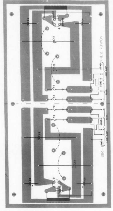
FIGURE 29: Stuffing guide for power supply board 1.
The six wires from the transformer box are connected through a mufti-pin connector on the back panel. I use LEMO or FISCHER (makers of the excellent CAMACs) six-pin connectors for this purpose, but I am sure you can find others that are suitable.
In any case, I recommend that you use a connector with some sort of locking mechanism.
Although the cartridge loading capacitor, C1, can be soldered directly on the RIAA-1 boards, it might not be the best solution for you. (Do not forget to subtract 60pF from the recommended value, which is the in put capacitance of RIAA-1.) If you have several phono cartridges that re quire different loading caps, you should consider either a small switch on the back panel or an extra set of phono inputs connected in parallel with the main ones. You can then make a set of phono plugs with the different loading caps mounted inside and plug these in to match the cartridge used.
All signal wiring is done with low noise, low-capacitance coax or twin lead shielded cable. Balance control wiring must be twin-lead shielded cable. Power supply wires are 0.5 square mm Litz (AWG 21 or 20).
Switches SW1 and SW2 should have gold-plated contacts. For SW1, I used an ELMA type 01 (break before make) miniature switch, which is often used in professional audio equipment. The volume control must be a high-quality, low-noise, low-distortion tandem potentiometer with good tracking. It may also be a dual-shaft type, in which case you do not need the active balance control indicated with the line amplifier. I have been using the Alps 20k volume control (sold by Old Colony) in one of my prototypes, and a smaller Alps device (type K272A) in a slim-line version of the preamp.
The boards were originally de signed for horizontal mounting, and two of my prototypes are made this way. Due to the rather generous size of the boards, however, you need a lot of real estate for this. Minimum mounting surface for the preamp shown in Fig. 34 is 420mm wide and 360mm deep. Add some extra millimeters to the width if you plan to have shielding walls between the boards.
Figure 35 shows a typical mechanical layout with “horizontal” placement of the boards in a 19-inch box.
The boards and all components fit nicely into a slim-line one-unit-high 19-inch box. The Old Colony 20k Alps fits in a 1-unit box if internal height is 36mm (1.42 inches). All you have to do is bend the soldering pins and put some tape on the inside of the top cover. (The Alps K272A fits very well without modification.| With a two-unit-high box (or some thing in between), you have plenty of space for the Old Colony Alps pot and all sorts of sophisticated switching arrangements on the front panel.
Alternatively, you can mount the boards vertically. In this case, cut about 10mm (0.4 inch) off one side of the boards and mount them in a 10mm (4-inch) high box. Use L brackets for mounting the boards.
Naturally, the mechanical arrangement shown in Fig. 35 is not the only setup possible. In addition to put ting the transformer(s) in a separate box, you can move the power supply board into this box as well. The interconnecting cable will then carry DC voltage instead of AC. If you choose this solution, I suggest you use the RIAA-2 boards as line amps because they have on-board regulators. You may then put power sup ply board 1 without regulators in the transformer box to limit the number of interconnecting wires, as in Fig. 34. This arrangement will save surface area in the preamp for future expansion.
I would like to conclude with a few comments from a friend who is a professional reviewer of high-end audio equipment. He made a “private ”' review of this unit and reported that it sounds homogeneous, with no special area being over-pronounced.
He noted that it has a wide and deep sound stage, very wide dynamic range and an excellent low-level resolution. He recommends that you leave the preamp on all the time for best sound quality.
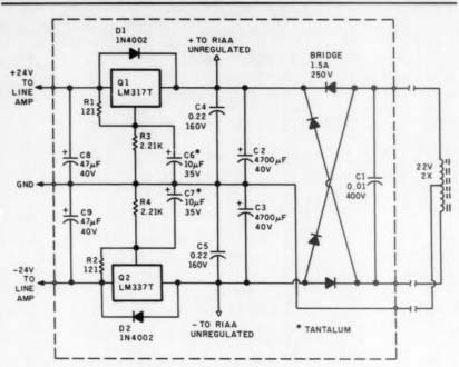
FIGURE 30: In power supply arrangement 2, one board supplies one channel
of a stereo amp.
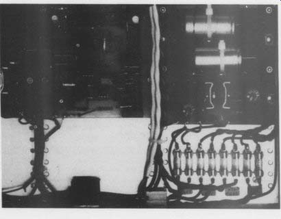
PHOTO 5: Notice the fuse block next to the power supply boards.
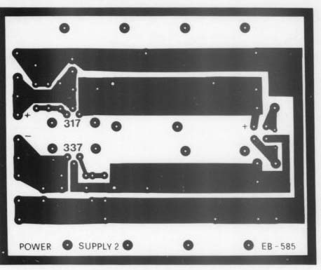
FIGURE 31: Circuit board layout for power supply board 2.
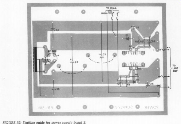
FIGURE 32: Stuffing guide for power supply board 2.
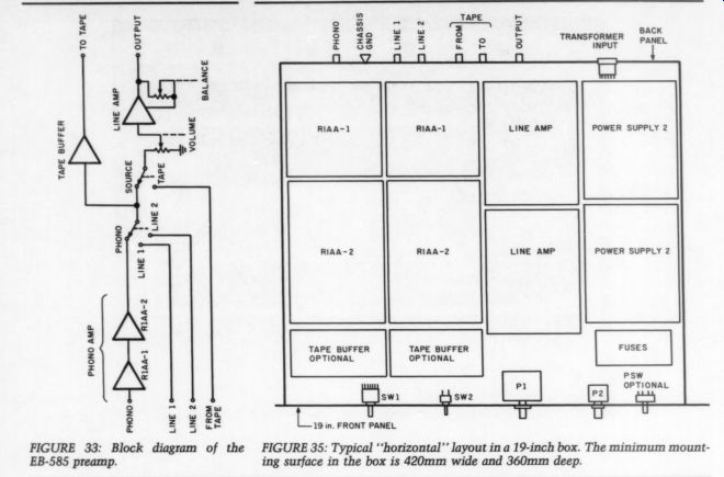
FIGURE 33: Block diagram of the EB-585 preamp.
FIGURE 35: Typical 'horizontal' layout in a 19-inch box. The minimum mounting surface in the box is 420mm wide and 360mm deep.
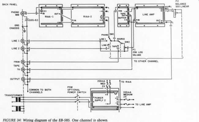
FIGURE 34: Wiring diagram of the EB-585. One channel is shown.
-------------
If you should have a TECHNICAL QUERY about an article appearing in this magazine, write it clearly, leaving space for a reply and referencing the magazine, the article and the page about which you are inquiring. Enclose a self-addressed stamped envelope and send these to Audio Amateur, Technical Dept., P.O. Box 576, Peterborough, NH 03458.
Help us by not calling in your question. We have neither the staff nor the time to respond to technical questions by phone.
-------------------------
Also see:
PREEMINENT PHONO PREAMP, By John H. Roberts