By Fernando Garcia Viesca
ADCOM GTP-400 Reviewed by Fernando Garcia Viesca THE FIRST QUESTION: do we need another tuner/preamp? If the design offers impressive specifications or has unique features, the answer is yes. The ADCOM model GTP-400 is such a device (Photo 1). After listening to the ADCOM unit for several weeks, I find its impressive specifications, sonic quality and out standing performance difficult to improve upon.
Features The GTP-400 has several important features; among them, separate RECORDING and LISTENING rotary selectors independently allow you to listen or record to Phono, Tuner, CD, TAPE 1 or TAPE 2. ADCOM advises that TAPE 1 and TAPE 2 may be used as any high level input, but have the added bonus of being ‘cross-dubbing ’ monitor outputs on the rear, enabling you to easily connect add-on circuits. The BASS, TREBLE and BALANCE controls are center detented, and the large VOLUME control knob allows fine adjustment.
Pushbuttons control the selection of AM or FM, saving and recalling up to eight stations (each of which lights up when in use), FM scan, Contour, Mono, Muting/Hi Blend and tuning. The GTP-400 tunes in 0.1MHz increments instead of the familiar odd-order 0.2Mhz, allowing its use in countries where the tuning format is different, but slowing down the tuning process. Muting is always in effect during either manual or automatic tuning.
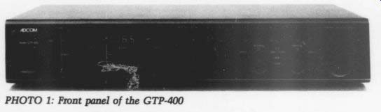
PHOTO 1: Front panel of the GTP-400
ADCOM wisely chose to omit such items as subsonic filters and stereo enhancements, since these built-in devices satisfy few people.
The rear panel offers phono jacks, switched and unswitched convenience outlets and antenna inputs, all neatly arranged. The FM antenna may be either flat twinlead 300 ohm or coaxial 75 ohm. Accessories included are loop AM antenna, dipole FM antenna and gold-plated, audio-quality phono cables.
The Guts
I’m an engin-ear who loves music and the means to product it; immediately
after a quick operational check the first thing I do-you guessed it-is open up the unit and follow the circuit. I do this for three reasons: to review the circuit design, to see the type of components used, and to look at the quality of the assembly.
Without its cover, the GTP-400 looks like a VCR-type assembly. Most of the circuitry is on a large board (Photo 2), but seven smaller boards contain components for the front panel switches, head phone amp and displays. Except for short jumpers, no audio signals leave the main board.
Some semiconductor statistics may give you an idea of the circuitry ’s complexity: 33 diodes, 14 LEDs, 41 transistors (10 FETs), 17 ICs (two large-scale integration) and three voltage regulators.
Since the unit doesn ’t come with a schematic I had to visually count the components. Part of the boards are hidden and I did not want to disassemble them, so I may have missed some semiconductors.
---------------
MANUFACTURER’S GTP-400 SPECIFICATIONS
Capture Ratio 1.7dB
Alternate Channel Selectivity
(+400kHz) =75dB IF Rejection =90dB Image Rejection (+ 400kHz) =80dB Separation (@ 1kHz) =50dB Frequency Response (+ 0.5dB) 30Hz-15kHz AM Tuner Section Sensitivity 300uV/m Selectivity (+ 10kHz) 40dB Image Rejection 42dB IF Rejection 70dB Signal-to-Noise (@ 5mV/m, weighted) 45dB General Power (available in other voltages on special order) 120V AC/50-60Hz Power Consumption 20W Chassis Dimensions 17 ’ by 11% ’ by 3 ’ Maximum Dimensions 17 ’ by 12% ’ by 3% ’ Weight 11.51bs.
Input Sensitivity (rated output) High Level 310mV Phono 3.3mV Tone Controls Bass (@20Hz) + 10dB Treble (@ 20kHz) + 10dB Loudness (volume @ 9:00 o ’clock) 100Hz + 5dB; 20Hz + 10dB Crosstalk (@ 1kHz) 80dB FM Tuner Section Usable Sensitivity (mono) 19uV/11dBf Quieting Sensitivity (50dB) Mono 2.5uV/13.5dBf Stereo 38.5uV/36.8dBf Signal-to-Noise (@ 65dBf, weighted) Mono =80dB Stereo =75dB THD + Noise (@ 1kHz, 65dBf) Mono =<0.08% Stereo <0.1% Preamplifier Section Output Impedance Main Out 1000 Tape Out 5000 Output Level (main out) Rated 2V Maximum = 10V Frequency Response (+0.5dB) High Level 10Hz-100kHz Phono 20Hz-50kHz THD + Noise High Level 0.009% Phono =0.08% IMD (SMPTE) High Level <0.005% Phono =0.008% Signal-to-Noise (rated output, weighted) High Level >=95dB Phono =80dB Input Impedance High Level 18,0000 Phono 47,0000
----------------
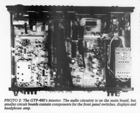
PHOTO 2: The GTP-400 ’s interior. The audio circuitry is on the main board,
but smaller circuit boards contain components for the front panel switches,
displays and headphone amp.
The synthesized phase-locked loop (PLL) FM section has a double- gate FET front end. A large-scale integration IC controls the digital display and provides tuning voltage for the local oscillator.
This circuit may also enable tuning memory. The signal strength meter uses a bargraph driver IC. PLL techniques using dedicated ICs demodulate the stereo.
Tuning coils are remarkably absent. Ancillary circuits are used (I suppose) for automatic frequency tuning (AFT) and some sort of stereo processing. Unfortunately all ICs have Far East part numbers, for which I don ’t have information.
We’ll have to stock Samsung and Toshiba semiconductor data-books alongside National and Motorola.
The AM section shares the FM controller IC, but the RF follows a different path, with dedicated circuitry. The front end also uses a FET. A separate IC handles the IF gain (and, I suppose, de modulation). Compared to my Lafayette tuner made in the early seventies, I am simply amazed how circuit designs have changed; I remember the days when I could completely follow a tuner’s circuitry without a schematic.
The phono section is a straightforward topology using independent op amps for each channel. All resistors are 1% metal film, all capacitors are polypropylene. I suppose the ADCOM house number op amps are high-quality commercial ones selected to ADCOM’s specifications. The circuit performs impressively.
The tone control section shares the same design philosophy: metal film resistors, polypropylene capacitors, and two house number op amps per channel (although these are different from the phono devices). I would be hard put to find an easy upgrade in the phono and tone control sections; ADCOM has done an excellent job.
The power supply, as I mentioned earlier, has three-terminal regulators, two of which are ADCOM house numbers, but it also uses several transistors and controls the muting relay. The power transformer is tucked well away in a corner with a separate custom engineered for ADCOM board. A fast-blow fuse protects the circuitry.
Last, the microprocessor controls all panel functions and provides a stable frequency (via a crystal oscillator) to the tuning PLLs and (I suppose) the FM scanning features and tuning memory. I was puzzled by ADCOM ’s warning that since unplugging the preamp for long periods will cause memory loss, it uses some static RAM; I could not find the energy backup.
Measurements
There are two ways to test audio gear: first, check the manufacturer ’s publish ed specifications; second, test the equipment for which the manufacturer does not publish specifications. As a seasoned engineer and audiophile, you will gain in sight into the equipment ’s overall performance and design detail.
I randomly tested several parameters and all met the published specifications.
When there was a disagreement, it was slight and I know it may be traced to such differences as test equipment or setup.
Starting with the line level section, harmonic distortion was an inaudible 0.003% with a 0.5V input level and maximum volume. Signal-to-noise ratio (S/N) was an impressive 94dB. With maximum volume control and all tone controls flat, gain was 15.8dB, giving a 3.1V output for the conditions stated above. This should be more than enough to drive any power amp. The main output impedance is remarkably low (1000), so you could easily drive several amplifiers in parallel. This may even allow you to discard the buffer stage in a biamped system crossover filter, eliminating an active component in the signal path.
The required line level input for a 1% distortion was 1.95V, with an output level of 12.1V. Such headroom is more than adequate for even the strictest digital sources without any fear of clipping.
Frequency response from 20Hz-30kHz (my generator range, 1kHz reference) was within +0.38dB. For all practical purposes it is ruler flat. I was clearly impressed, however, by the tone control response.
First, the tone control (bass, treble, contour) effect in the midband was negligible. Even at maximum or minimum settings, the effect at 1kHz did not deviate more than 0.6dB. I cannot over emphasize the importance of this, since a poorly designed tone control smears in to the midband, causing a clearly audible unnatural effect. Bass boost/cut was +11.5/-11.5dB at 20Hz (from a published + 10/ - 10dB) and at the center de tent, 00 dB. Treble boost/cut was +8.6/ -8.6dB at 20kHz (from a published + 10/ - 10dB) and also 0-dB at the center detent. I don ’t believe the small performance differences are detrimental; rather, the exquisite tone control symmetry, which gave a true zero at mid point, is relevant.
ADCOM's Contour pushbutton differs from the traditional loudness response; only the low-frequency area is affected, leaving the high frequencies undisturbed.
ADCOM claims that studies from Robinson and Dadson of Harvard showed this enabled easier listening. I measured a +10.31dB bass boost at 20Hz and 0dB response at 20kHz.
The headphone amplifier gave a strong 5.1V output before clipping into a 100 Ohm load. With the large dynamic range of the preamp, this level is enough to split your eardrums if you accidently drop the phono tonearm while wearing your head phones.
The phono section measurements were just as good. Gain at 1kHz was 39.5dB. Harmonic distortion and S/N at this same frequency and a 5mV input were 0.045% and 67dB, respectively.
Specifications quote a better S/N measurement, but since the weighting filter was not specified, I did not use one. The input amplitude required to reach 1% distortion at this frequency was 88.5mV, giving a headroom of 25dB.
RIAA frequency response was accurate within 0.3dB, which reflects careful design and quality components. For the FM tuner section, measured harmonic distortion and S/N was 0.075% and 79dB for a mono signal at 60dBf input into 750. The muting circuit was remarkable.
When the signal reached 30dBf the muting worked effortlessly, and the level could increase to 33dBf before the muting circuit cut out. This signal hysteresis is useful in avoiding what I call ‘squelch chatter’--the audio turning on and off annoyingly. The signal strength bargraph stops reading at 17dBf, but even at this low level, I could listen without hearing appreciable noise. Unfortunately, I did not have a stereo generator available to test the FM stereo features. I tested only a couple AM parameters, and came out within specifications.
Last, I tested miscellaneous parameters. Many manufacturers dread these tests because they impose strenuous limits on the equipment. They also indicate the equipment ’s survival capability.
I applied a surge test of 10V AC, each 150V and 100msec wide. The AC input fast-blow fuse located inside the unit blew, as it should. It doesn ’t matter whether protective devices trip, only that the equipment survives the test.
Next I applied cycle dropouts, which tests the power supply design. Energy storage and rejection of line transients are quickly revealed in this torture test, in which I completely dropped off full AC cycles within 1sec (60 full cycles). The unit should be tested in the low range of the input voltage. The GTP-400 passed the test with flying colors, since it required dropping three full cycles at 110V AC before the muting relay came into action. The usual record is about two cycles. Judging from the signal on the oscilloscope, I think if the relay had been eliminated the power supply could have withstood a four-cycle dropout before transients appeared at the output.
I tested cutoff voltage next, which is similar to the previous test except I applied a continuous AC voltage that I slowly lowered until the equipment failed, which happened at 87V, more than adequate to handle summer brownouts. The S/N increased at this low level.
In two tests the unit did not perform well. I have seen countless devices apparently damaged by electrostatic discharge (ESD). ESD was unheard of in consumer electronics about ten years ago, but with units packing more and more powerful digital processors for control or signal, immunity to this effect has become increasingly important. A single bit disruption may put your unit totally out of control.
Worse yet, this disruption triggers a parasitic silicon-controlled rectifier (SCR) inside the IC where the malfunction occurs. The IC starts to draw inordinate amounts of current until it burns out, a process that often destroys adjacent circuits in a deadly domino effect. Once the parasitic SCR is triggered, you can stop it only by cutting off the power, but you may not be alerted to the malfunction until the acrid smell of burnt plastic permeates the air.
In the ESD test I applied a 5kV integrated electronic component pulse to several parts of the chassis, since in the dryest seasons 5kV is an easily attained, moderate amount of ESD. Apply the test pulse randomly, since you don ’t know pr area of the chassis you may touch first.
The chassis is all metal, so the test progressed nicely. When I put the probe tip on the listening selector, however, a spark flew into the inside of the unit, making the tuner ’s digital display flash zeros. I turned off the unit, then turned it back on after a few seconds passed with no further malfunction. I applied the probe to the same selector; another spark and the display went blank. I turned off the unit again and decided not to repeat the experiment lest I destroy the unit.
I am not blaming ADCOM, for most equipment fails my ESD test. I am sure ADCOM engineers soon will be correcting this problem.
The AC transient did not really fail my test, since I decided to analyze the circuit rather than test it. Many events interfere with the electrical supply in your home. Lightning strikes, high-voltage transformers cutting out and substation switching all send deadly ripple voltages (kilovolt levels, though of microsecond duration) to unsuspecting users. This phenomenon is common, but for the same reasons mentioned with ESD, until ten years ago the problem was un noticed in consumer electronics.
I decided not to perform this test since I did not see a quenching device (varistor, spark gap) inside the unit. Fuses are not fast enough and I didn ’t want to destroy the unit. Again, most manufacturers do not properly address this problem.
Listening Tests
If I had to define the GTP-400 ’s operation in a few words, they would be:
quiet, accurate, gentle, friendly. I chose quiet not only because of the unit ’s impressive S/N, but also because the muting relay silences all the turn-on transients that can be so disturbing. Also, the FM muting feature performed flawlessly, muting without any sharp transients or noises.
I call it accurate because of the smooth action and response of tone controls. It is gentle because the FM muting/blend was so subtle as to be almost un noticeable. I particularly liked this feature since it enabled me to listen to stations I usually tolerate for only a few moments.
I found it friendly because of the easy control of its powerful features. As I stated before, I would find it difficult to improve the sound of the unit. The bass is powerful yet not boomy, the treble gives crystal clear response. The tuner section is sensitive and stereo separation (I performed A/B tests with another high quality tuner) is superb. Contour is certainly more natural sounding than normal loudness controls.
I appreciated the unit ’s low output impedance. I removed the first buffer stage in my biamped system without any audible or measurable loading. I admit, with difficultly, that this unit is much quieter than my custom-made preamp. Also, its stylish appearance blends easily with other high-tech consumer devices.
Most remarkable of all this unit ’s characteristics is its unbelievably low price.
The music lover will be hard put to find more preamp performance for this price.
And the tuner, given the cost, may be regarded as a gift.
Criticism
We must, unfortunately, look for faults in a well-made device, otherwise a review will be product propaganda. My few criticisms of this unit follow.
Why has ADCOM (and many other companies) assumed the nasty habit of not providing a schematic? The obvious answer is to assure factory service. There are times or places, however, when you must service it elsewhere. Also, the serious audiophile would prefer to know the circuit topology. Despite that deficiency, the manual accompanying the unit is exceptionally well written and otherwise complete.
The FM ENTER pushbutton is positioned close to the memory recall pushbuttons, is identical in appearance and easy to confuse, and once pushed, you cannot cancel the command. If you push the button of the station currently in use, it still will not cancel. You must enter another station, destroying the set ting you have saved.
Last, I think ADCOM should provide some form of varistor or spark gap with the unit to protect sensitive circuits.
Victor Campos of ADCOM comments:
We would like to thank TAA and Mr. Viesca for the great review of the GTP-400. There are a few points I would like to address. First, the GTP-400 is, in fact, provided with 'a quenching device' on the AC power line. There is a metal oxide varistor (MOV) on the primary of the power transformer, mounted on the underside of the circuit board in which the strapping for multi-voltage operation is performed. Perhaps Mr. Viesca mis took this MOV for a capacitor, but the GTP-400 is protected from power line spikes and other high voltage surges.
Second, service manuals are available for all our products and can be obtained from us for nominal cost. The service manuals contain not only the schematic, but parts lists and other necessary data.
We were quite surprised at the experience Mr. Viesca had with the listening selector and his 5kV static discharge.
In fact, the switch shaft is designed to provide a small gap between the shaft, which is insulated, and the chassis, which is steel. This small gap is intended to prevent any such occurrence by bleeding the static discharge. We will be investigating this situation when we receive the unit back from Mr. Viesca.
Editor ’s Note: At ADCOM ’s request, Mr. Viesca repeated his experiment for ESD immunity after grounding the chassis as suggested in the User ’s Manual. He reports that if the unit is grounded it is, as the manufacturer suggests, immune to ESD.
Also see:
Link | --A SIMPLE HIGH-QUALITY CD OUTPUT AMP, By Jan Didden
AC SENSING CONTROL, By LB. Dalzell
EDITORIAL Bags & Taxation