BY J.M. DIDDEN
I STARTED THE DESIGN for my CD output amp as a result of my ideas about a systems approach to audio design, on which I based my recent article (TAA 2/88). All components in a system should be simple, direct and designed with the rest of the chain in mind.
The first component I tackled was my CD player, specifically its analog output section. In Fig. 1 the schematic for one channel is shown.
I don ’t think I must explain why I want to do without the output coupling electrolytic (2758) and the output series mute relay (1660, 'kill'). I believe these types of components have been shown to audibly degrade the sound. If possible, I also would like to eliminate op amps 6675(a) and 6675(b). I believe this is potentially better than to try to find a better chip. Although we tend to think of op amps in terms of black boxes, they contain tens of active devices which in one way or another all degrade the signal.
Refer to the Jung/Childress discussion on other pitfalls of op amps for this application! As they explained, the first op amp provides current-to-voltage con version and the first section of a third order filter; the second provides a second-order low-pass filter. Relay 1658 (pre-emp) does the switching for the 50usec de-emphasis. This relay is switched by the CD subcode information (Fig. 6).
Only a third-order output filter is necessary since my Philips CD 303 uses four-fold oversampling (176.4kHz instead of the basic 44.1kHz); more on this later.
In my effort to keep the circuitry as simple and direct as possible, I came up with the current-to-voltage converter of Fig. 2. Actually, it can be done with just one transistor, but the DAC requires that its output remain within + 10mV from ground. The DAC output current is reflected in Re and can be picked off at the emitter of Q2.
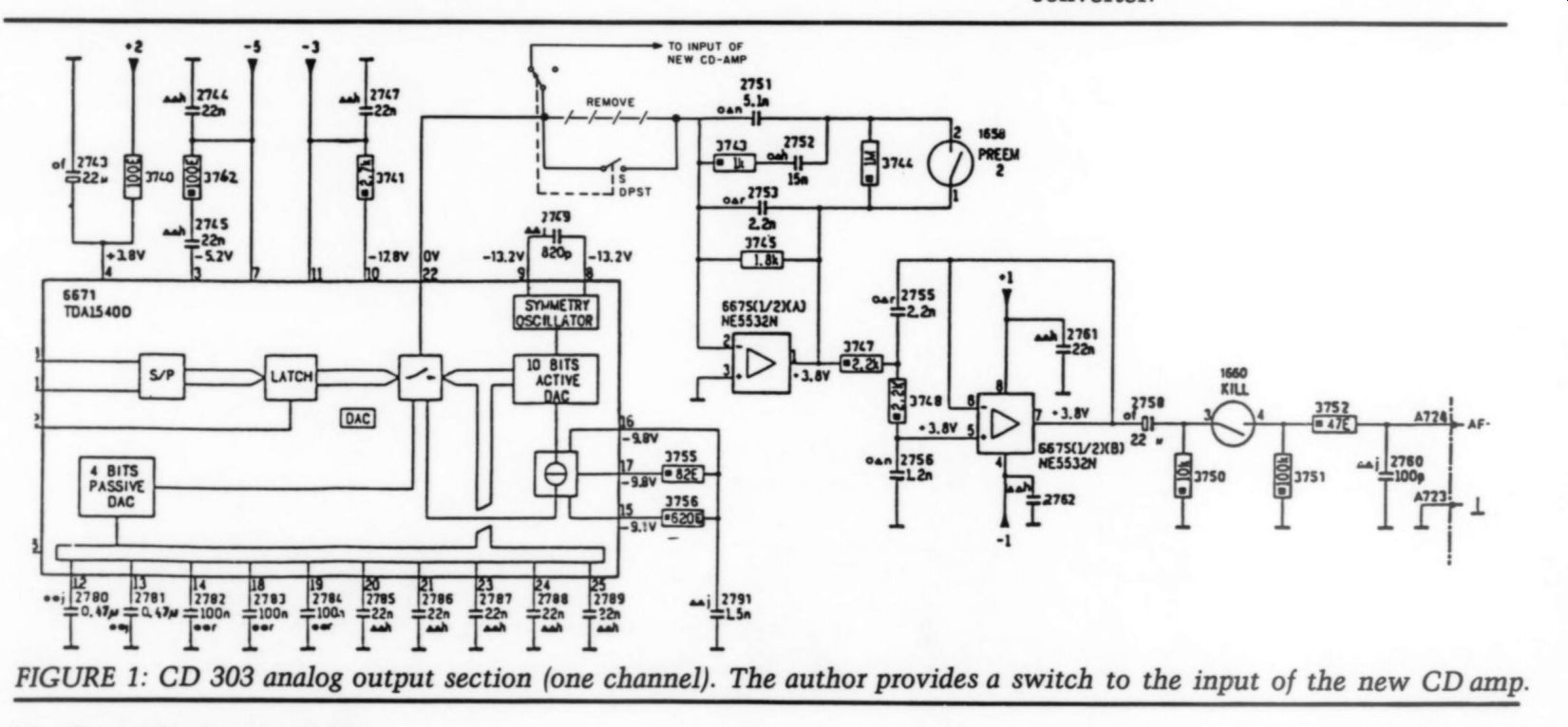
FIGURE 1.
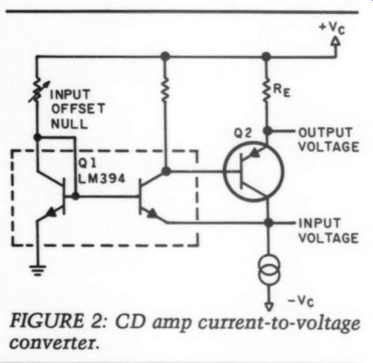
FIGURE 2: CD amp current-to-voltage converter.
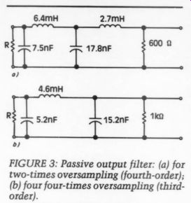
FIGURE 3: Passive output filter: (a) for two-times oversampling (fourth-order);
(b) four four-times oversampling (third order).
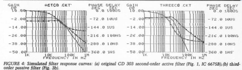
FIGURE 4: Simulated filter response curves: (a) original CD 303 second-order
active - (Fig. 1, IC 6675B); (b) third-order passive filter (Fig. 3b).
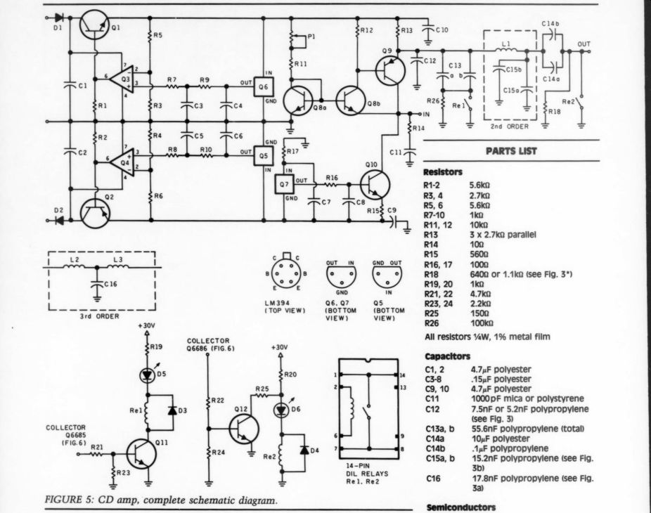
FIGURE 5.
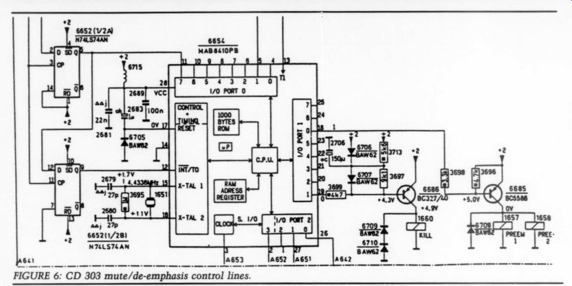
FIGURE 6: CD 303 mute/de-emphasis control lines.
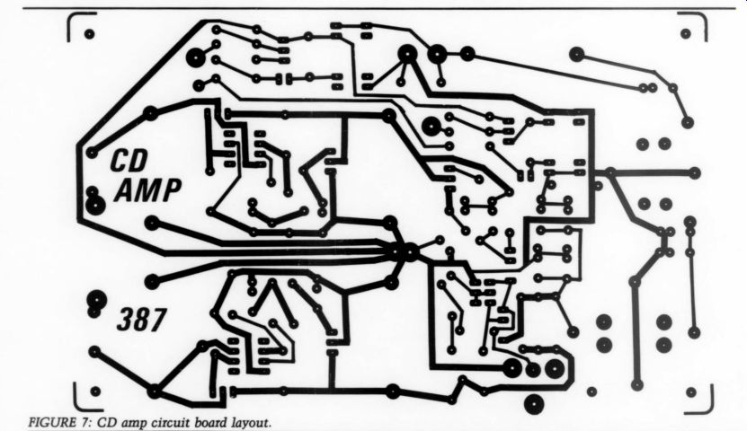
FIGURE 7: CD amp circuit board layout.
As you see, the output is referred to the positive supply line; I had to decide whether to use a high quality supply or add another stage. Since a high quality supply is desirable anyway, I chose not to introduce more active circuitry. The use of the LM394 provides an accurate and temperature-independent input off set null, which can be adjusted with the trimpot.
Output Filtering
All digital samples of the CD signal are coming off the disc at a rate of 44.1kHz, this is standard for any player. This means if we want to attenuate the switching components, a standard 50dB in relation to the highest audio signal, we need a filter that rolls off at 50dB/ octave. Such a filter is complex, expensive and ruins your phase response.
With four-fold oversampling, as used in my CD 303, each 44.1kHz sample is made into four samples that appear at the D/A converter at a rate of 176.4kHz.
The process involves repeatedly multi plying each original sample. It is done entirely in the digital domain and thus has no influence on the quality.
So now our filter must roll off 50dB between 22kHz and 176.4kHz, or about 18dB/octave. This can be done with the third-order filter, as shown in Fig. 1.
The active filter around 6675(b) with R3347, 3348 and C2755, 2756 provides 12dB/octave, another 6dB/octave is provided by R3745 and C2753 which also satisfies the default S5pusec de-emphasis.
The input rolloff of the preamp provides a safety margin where I normally use an RC filter at 30kHz. Some players use two-fold oversampling; the filter must roll off 50dB between 22kHz and 88.2kHz, or about 24dB/octave. My output amp can accommodate filters for both situations.
A passive filter is, I believe, inherently more neutral because of the lack of active circuitry in the signal path, provided you use high quality parts; but the same requirement holds for the parts of an active filter.
Arthur Williams gives an excellent design ‘menu ’ for these classes of filters. You can also use Robert Bullock ’s crossover design software ’ which gives almost identical results. The filter circuits are shown in Fig. 3.
I generated the filter transfer curves from Fig. 4 on my computer with an analog simulation program? The measured responses closely follow these curves.
The complete schematic is shown in Fig. 5.
The signal must negotiate just two transistors and some wire, instead of the tens of transistors hidden in an op amp. These kinds of circuits, simple, with low feedback, and without ...
-----------------
PARTS LIST
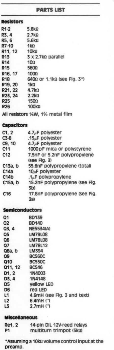
R1-2 5.6ka R3, 4 2.7k0 RS, 6 5.6k0 R710 1 k-O R11, 12 10k0 R13 3 x 2.7ka parallel R14 100 R15 5600 R16, 17 1000 R18 6400 or 1.1ka (see Fig. 3*) R19, 20 1ka R21, 22 4.7 k-O R23, 24 2.2k0 R25 1500 R26 100k0 All resistors Ww, 1% metal film Capacitors 2 4.7yF polyester C38 A5uF polyester C9, 10 4.7,F polyester cn ’ 1000 pF mica or polystyrene C12 7.5nF or 5.2nF polypropylene (see Fig. 3) 55.6nF polypropylene (total 10xF polyester AF polypropylene 15.2nF polypropylene (see Fig. 3b) C16 17.8nF polypropylene (see Fig. 3a) C133, b C14a C14b C153, b
Semiconductors
BD139 Q2 BD140 NE5534(A) Qs LM79L08 Q6 LM78L08 Q7 LM78L12 Q8a, b LM394 Q9 BC560C BC550C BC546 1N4003 1N4148 D5 yellow LED Dé red LED 1 4.6mH (see Fig. 3 and text) L2 6.4mH ( ‘) L3 2.7mH () Re1, 2 14-pin DIL 12V-reed relays m1 multiturn trimpot (5k2)
*Assuming a 10k2 volume control input at the preamp.
-------------------
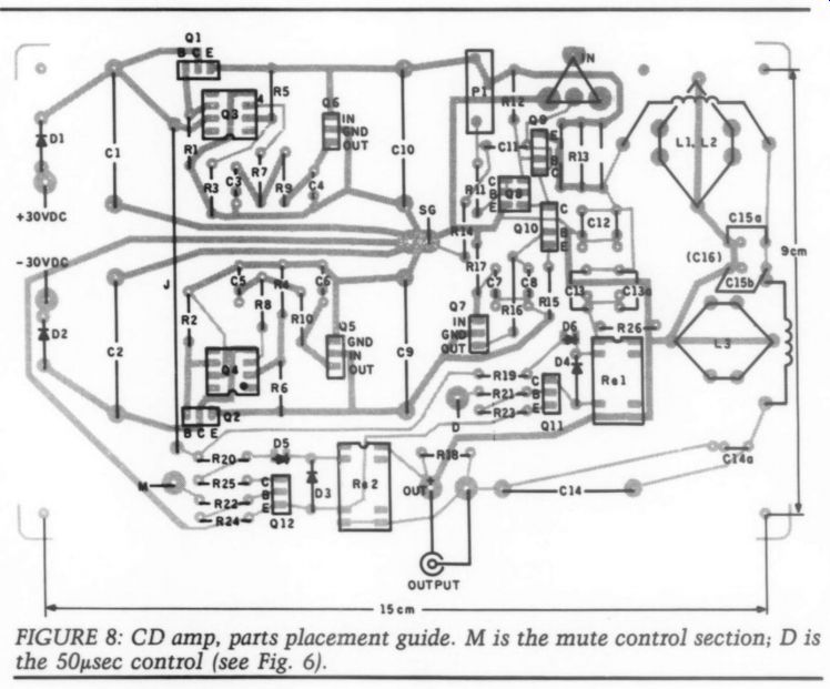
FIGURE 8.
.... the need for frequency or phase compensation, provide extremely high sound quality.
Note: After I submitted the draft of this article, I had the opportunity to audition the L ’Audiophile ‘‘Nemesis ’ single-transistor power amp at a high end show. Yes, that ’s right. Only one transistor (MOSFET SK135). The signal enters at the gate and emerges from an output transformer in the drain lead. I came away fully convinced that less is better.
The CD amp even measures well: at full input (1.4mA RMS) the output level is 0.7V RMS, with a 10kHz THD of less than .005%, almost purely second harmonic. Oscilloscope testing with fast input pulses simulating the DAC output showed no misbehavior.
Two control lines from the CD player must be brought out to the output amp. These activate the 50usec de emphasis, controlled by the disc sub code, and the mute or kill switch, used to mute the signal when severe drop outs are detected. Figure 6 shows where I picked off these signals.
The de-emphasis is switched to 50usec when the collector of Q6685 switches to + 5V. The mute relay is activated by the collector of Q6686 going to zero volts.
I changed the topology for the mute switch. It is not in series with the signal, but is used to short the output signal. I believe this setup further de creases signal contamination.
The design also includes a wideband power supply for each channel ’ The circuit needs +30V DC power. I did listening tests with four separate supplies for two channels, and with just two supplies with a common ground for both channels, and I could hear no difference. To minimize connections and solder joints, I used a gold-plated board mounted RCA socket for the input.
The output cable is directly connected to the circuit board, saving another solder and plug connection. The circuit pattern and parts placement for my unit are shown in Figs. 7 and 8, with the Parts List.
Building Coils
For the coils I used a type 2213 potcore (22 by 13mm), which is an industry standard size. They come in various
‘magnetic sizes, ’ and we want an Al value of 400. (The Al value is the inductance (in millihenrys) for 1000 turns.) The number of turns required N = 1000 (inductance/A1). Thus, for L1, N = #107; for L2, N = #127; and for L3, N = #82 turns. I used a double strand of enamel-insulated .22mm wire (I guess thats AWG 31). [AWG 31 is 0.227mm in diameter; AWG 32 is .202mm.-Ed.]
Use Litz if you can get it. Do not solder the wire ends to the core assembly terminals; I connected them directly to the board to avoid another two solder joints. See Fig. 8 for more details.
That ’s all there is to it. Do not forget to jumper the L3 terminals if you use the third-order filter. Discard the adjustable center slug if it was provided with your cores.
Customizing Although I use the amp for my Philips CD 303 player, it would be particularly suited to any of the other Philips/Magnavox types ’ You can use it for any brand, on two conditions. First, the player must have DACs with a current output. See also further considerations discussed in TAA ’4S If your unit has voltage-output DACs, see whether you can replace them. This eliminates another not-so hot op amp from the signal path. Most DAC types have interchangeable versions with either current or voltage output.
Also, your player must use at least two-fold, preferably four-fold oversampling, otherwise you need a much steeper filter. With the help of Williams, such filters are perfectly feasible, but I have not tried them. Another area where you are on your own is the mute and de-emphasis switching. You must find a suitable control signal that can be used to switch the DIL relays. This is normally not difficult, but a schematic of the output section of your unit is essential.
I am willing to provide customization advice if you send me a schematic diagram of your player through Audio Amateur.
As shown in Fig. 1, I provided a switch to select the original output or the current output, but this is just for comparison purposes. The current output is taken directly from the board through a fixed cable, avoiding the extra connections and joints of an output RCA jack.
Let me conclude by saying that this change caused a marked improvement in my CD ’s playback quality. The difference with my tuner and record player is much more pronounced. Much greater detail in the soundfield is audible; I can distinguish individual instruments and voices much better.
I now also detect greater difference in sound quality between CDs, where with the stock player they all sounded more or less alike.
This is a simple, inexpensive but very effective upgrade. Next, I will try to improve the circuitry around the TDA1540 DAC, per Jung/Childress.
REFERENCES
1. Jung, Walt and Hampton Childress, 'POOGE-4,' TAA 1,2/88.
2. Williams, Arthur B., Electronic Filter Design Handbook, McGraw-Hill, ISBN 0-07-070430-9, paragraphs 3 and 9.4; table 2.18.
3. Old Colony Crossover CAD program, OCSL SBK-F1A.
4. Microcomputer Circuit Analysis Pro gram, Spectrum Software, 1021 S. Wolfe Rd., Sunnyvale, CA 94087, (408) 738-4387.
5. Didden, J.M., ‘A Wideband Power Supply, ’ TAA 1/87, p. 22.
6. Childress, Hampton, ‘Modifying Yamaha ’s CD2 Player, ’ TAA 3/86, p. 14.
Also see:
Feed Forward Error Calibration
A MULTI-TONE INTERMODULATION METER, PART 1, By Erno Borbely