A ROTATABLE ANTENNA
TO IMPROVE FM RECEPTION, some people simply don't have the attic or roof space that a full-size Yagi or periodic log array requires. A useful compromise that works well inside wood-framed structures is the rotatable 300 ohm dipole antenna. Although this type lacks the directional gain features of a multi-element array, it does have a full 360° capability and is easily adjusted.
Figure 1 shows the antenna arrangement and its resulting coverage. I chose a compromise length of 62 inches for the dipole, which I then attached with electrical tape to the narrow side of a 64-inch length of 0.5” - by 3 1/4-inch wood trim.
Woven nylon fishing line is then tied and taped to each end of the wood trim forming a small loop about 1/4-inch above the top surface of the wide side of the wood and 1/4-inch from each end.
Next install a series of small hooks (commonly called teacup or coffee-cup hooks) in a ceiling corner of the listening area. Using the wood trim as acom pass, place one end in the corner narrow side up and place a pencil next to the other end. Lightly draw a 90° arc on the ceiling. With a 64-inch radius, this arc should be close to 100 inches long. Sub divide this arc into 16 equal (6 1/4-inch) segments; use a metal tape measure on edge to check this curved length. Each segment should correspond to 5%°.
Screw one of the hooks into each of the 15 middle cross-points on the ceiling. The pivot hook should be screwed in about 1-inch away from each wall, and also the hooks for each end of the arc.
Now place one loop on the pivot hook and the other loop on any other arc hook.
Connect the lead to your receiver in as straight a line as possible and tune in a station. Find one of the 17 positions which provides the best reception for that station. If you wish, you can remove any hooks that do not provide good reception of your frequently listened to stations. I left all of my hooks in, to be able to pick up Houston, San Antonio, and other Central Texas stations.
The FM dipole provides good reception from front and back, but little or no reception can be picked up from the ends.
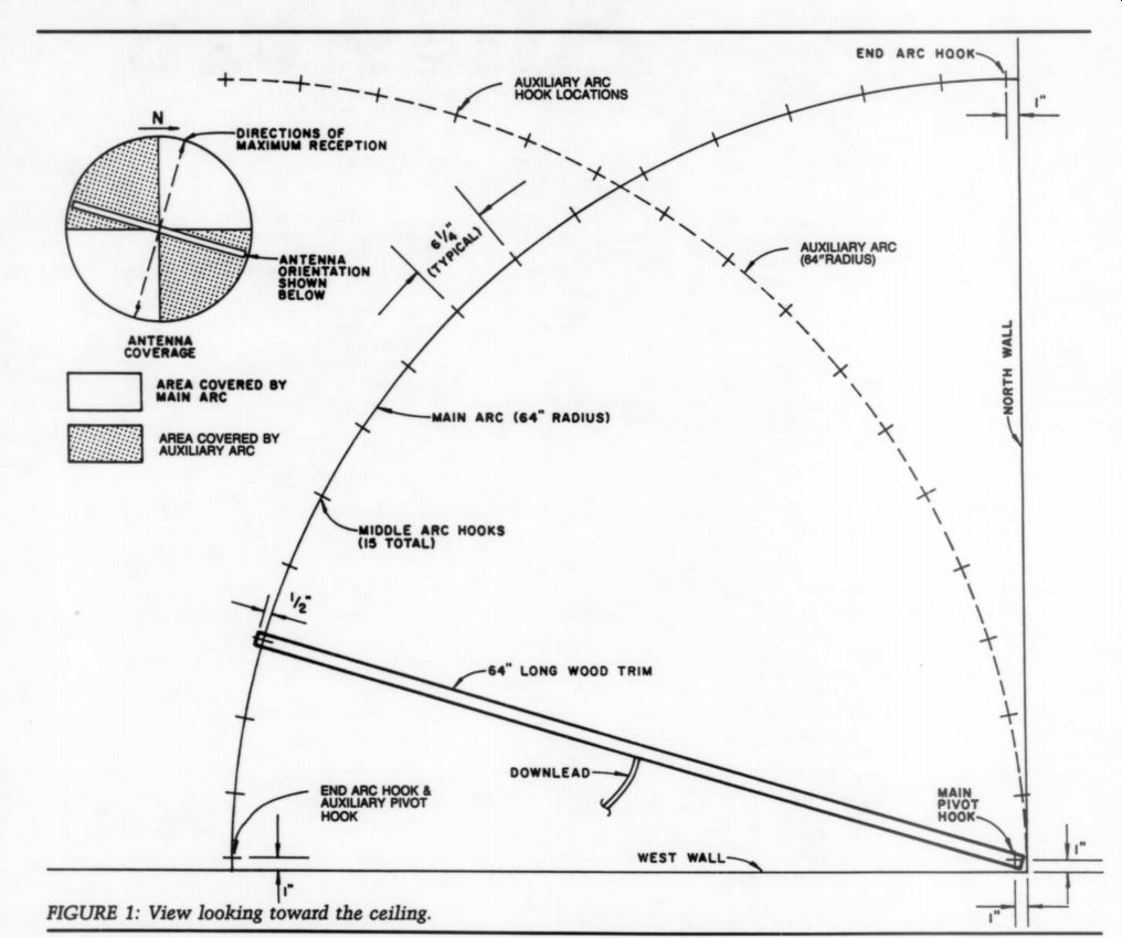
FIGURE 1: View looking toward the ceiling. CEILING DIPOLE ANTENNA TAPED
WOOD TRIM DOWNLEAD
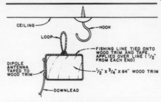
FIGURE 2: Close-up of hook attachment.
Therefore, the reception pattern consists of two back-to-back 90° arcs. If a station is just beginning to be picked up on one of the arc end hooks (the ones next to a wall), then that station lies in a direction beyond your positions, somewhere in the other two back-to-back 90° arcs. To cure this problem, use one of the arc end hooks as an auxiliary pivot hook, and draw a new 90° arc. Subdivide and mount additional hooks as required for full 360° coverage.
The unsightly appearance of hooks, wood trim and down-lead in your listening area can be easily tolerated when listening to the gorgeous sounds of a well tuned-in signal. My antenna can pull in both a 1,600W community station just west of Austin, as well as a 50,000W PBS station 75 miles to the north, even though they are nearly 90° apart.
STEVE BALL; Austin, TX 78745
A SIMPLE RUNNING TIME METER
SOME PIECES OF EQUIPMENT need regularly scheduled maintenance to ensure excellent sound quality. This maintenance is usually related to the total usage which varies over time. Two pieces of audio equipment that are most known to need regular cleanups are the tape or cassette recorder and the stylus of phono cartridges, that is, if you do not clean before each use.
Other pieces might need to be adjusted or cleaned regularly too, for example, a tube amplifier bias. To manually monitor the total time a piece of equipment is used is cumbersome. We must take note of each use-starting and finish time, compute the difference, and keep a total for each piece of equipment.
A solution is to use running-time meters.
Commercially available meters al ready exist, so you might wonder, why all this fuss? The answer is simple: most types of running-time meters are AC operated, use 2-4W, and are big and somewhat expensive. The other type I know of is an electronic clock with battery backup, which costs even more.
The catalog from Allied shows elapsed time indicators from $20-60, and running from 12-24V DC or 120V AC (page 590-591).
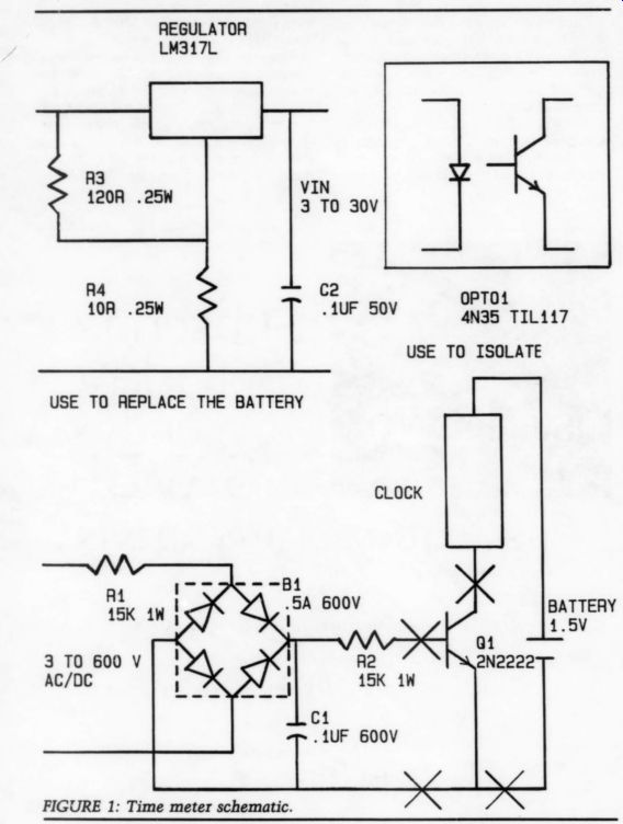
FIGURE 1: Time meter schematic.
The meter I propose is different, more flexible, more easily available and some what cheaper. If you need a short duration (less than 12 hours) running-time meter, first, buy a small, cheap (less than $10) battery operated, quartz alarm clock. Then use any of the following circuits to power it up (Fig. 1). These clocks take very little power from the battery (less than 40uA at 1.25V), so you can probably take the power from the device it is timing. If you cannot do that, you can power it from a battery and control the clock with a voltage operated switch.
This timer can be used in other applications. In fact, it was originally de signed to monitor the time a motor, driving a compressor, was running.
From this data, I estimated the reliability of this motor.
The voltage sensing circuit can be installed inside the clock body but you might have to remove the alarm circuit and buzzer. The alarm is a helpful re minder that a limit is reached.
You could also install a shorting jack so that the clock runs normally by itself and, when needed, plug the voltage sensing switch in.
The circuit is quite simple. The bridge converts AC into DC. If you monitor a DC voltage, take the bridge out and connect the positive voltage to the base of the transistor through the two resistors.
These resistors drop the voltage to a reasonable value. The capacitor between them filters the rectified DC and any noises. If battery operation is not desired, use the voltage regulator circuit.
Y If monitoring AC voltage without a battery, use the opto coupler to isolate the two circuits, making sure the two ground connections are separate.
Specifications: total time, 12 hours; accuracy, 1 second; drain, minimal; limit alarm, included and adjustable; total price, $15-20; battery life, one year.
DANIEL DUFRESNE
Saint-Laurent, Quebec Canada H4L 454
MODIFYING AR'S ORIGINAL TONEARM
PLENTY HAS BEEN WRITTEN about modifying the AR turntable to accept new tone arms. If you own an AR turntable with a built-in queuing lever (AR-XB), you may be able to get good performance by modifying the original arm. I've found that when the pivots are adjusted properly the friction for which some AR-XA arms were criticized is reduced. Also, perhaps due to dressing the leadout wires, I don't have problems from the lack of antiskating compensation.
I tried to avoid expensive, difficult, or time-consuming modifications, while retaining most of the excellent engineering which went into the original turn table. The modifications:
Replacing the headshell; coating the arm tube with epoxy; adding damping to the subchassis; replacing the output cables; hinging the lid, and replacing the platter mat.
You should write to AR (Teledyne Acoustic Research, Parts Dept., 330 Turnpike St., Canton, MA 02021) to obtain the overhang adjustment template, oil, owner's manual, and new bearings and belt. Specify ''old'' AR turntable or AR-XB, to avoid confusion with newer models. Clean and adjust all parts, and lubricate if necessary. Never put any substance other than silicone lubricant (available in auto parts stores) into the queuing damper well.
Arm Tube Mods
First, remove the plastic headshell. Loosen the screw where the arm tube goes into the pivot and slide the tube in to the pivot as far as it goes to allow some slack in the delicate wires inside the tube. Now pry the plastic sleeve which holds the headshell out of the arm; be careful so you do not break the internal wires when the sleeve comes free. Cut or un-crimp the tonearm wires where they attach to the headshell sleeve.
You can now remove the tube, and drill a 1/4-inch hole in its underside, about 1/4-inch from the headshell end (Fig. 1). With a small saw blade, cut a slit in the tube to this hole. This will allow you to fit a new headshell directly into the tube. I purchased an Audio Technica AT-D universal type, which combines a pleasing appearance with a simple design, but I imagine other head shells would work fine.
WIRES TIGHTENING PIN (REMOVE)
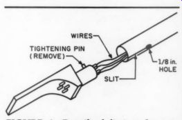
FIGURE 1: Detail of fitting the new headshell to the AR arm.
Cut off the small tightening pin on the cylindrical surface of the headshell. Be fore inserting the headshell, carefully slide the tonearm wires into the arm tube and again slide the tube as far into the pivot as possible. Then carefully solder the wires to the pins on the back of your headshell, observing the color coding. Now you can slide the headshell into the tube, prying the slit open slightly with a screwdriver. You may find it necessary to file the headshell surface down a bit. You can either allow the friction to hold the headshell, epoxy it in the tube, or use a small adjustable metal ring to clamp the tube about the head shell. I would avoid epoxying the head shell in case you need to rewire it or ad just the azimuth.
As shown in Photo 1, I attached an additional aluminum strut to the tonearm with silicone sealer to improve rigidity and distribute tonearm resonances, but the next step may obviate the need for this.
Damping and Mass
Since resonances in the headshell and arm tube can visibly affect the cartridge's frequency response as well as subjectively affect sound quality, I thought damping these components would be worthwhile. Also, I found that the AT head-shell's reduced tonearm mass makes balancing a light cartridge impossible. To dampen resonances and increase mass, I applied two coats of five-minute epoxy on the arm tube, avoiding the armrest area and where the headshell and pivot attach. (You should first make sure you can adjust the overhang correctly once you've tightened the arm tube-to-pivot screw.) For each coat, use a different watercolor brush and work quickly, since the finish will become rough if you try to apply the epoxy while it is beginning to harden.
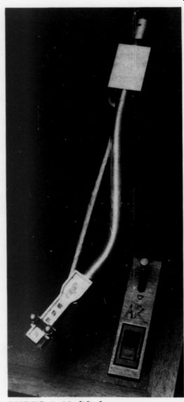
PHOTO 1: Modified tonearm.
I also removed the plastic decoration piece and filled the top of the headshell with epoxy, temporarily applying tape to the underside, so the epoxy wouldn't escape through the holes. Be careful not to use too much epoxy here or the arm lift will not fit correctly on the headshell.
Now attach your cartridge and align it. Set the overhang using AR's alignment template and place a small mirror on the platter to visually set azimuth and VTA. You can twist the arm tube where it connects to the pivot, as well as the headshell where it connects to the arm tube. In addition to setting the azimuth, these two adjustments can be made simultaneously to produce minor changes in VTA. AR also sells a good tracking force gauge.
Finally, since my cartridge (Ortofon X3 MC) has a fairly low compliance, I added cap nuts to the ends of the cartridge mounting screws to further increase the mass.
I epoxied pieces of 3/16-inch fiberboard to the aluminum under-chassis to dampen any tendency toward ringing. This is similar to Gary Galo's modification in TAA 3/85.
I replaced the output cables with a good turntable interconnect, including ground lead and gold-plated connectors.
To hinge the AR's lid, drill and countersink holes from the inside of the lid's rim, and use flat-head stove bolts to hold the hinge. While some say the lid induces resonances, removing it each time you put a record on is inconvenient and dangerous (you risk banging the arm).
Besides, a suspended-subchassis turntable should be relatively insensitive to these vibrations.
The original AR platter mat was in poor condition. I made my own from dense 1/4-inch foam rubber, cut in a donut shape to allow for the record label and record rim.
I prefer owning an inexpensive, soundly-engineered, and easily-modifiable component such as the AR turn table which I can refine as the art/science of sound reproduction progresses.
RALPH GONZALEZ;
Wilmington, DE 19810
STEREO POWER
AT ONE POINT in the evolution of my stereo system, many circuit enhancements were in place, but the bass just didn't sound taut and solid. I solved the problem by replacing AC wall outlets, updating the original two-wire receptacles with grounding three-wire receptacles. Buy a new outlet at the hardware store and examine it as you read this.
Wall outlets serve two functions. First, they provide a means to connect a load to the AC supply. Second, they have the practical function as joints for the sections of conductor, leading from the main fuse box, from outlet to outlet, to the end of each protected circuit.
The wall outlets are equipped with two ways to splice wires to them. The simplest connection consists of thin brass "jaws'' which grip the stripped ends of the wires, which you insert into holes in the back of the outlet. A far better connection is also provided, in the form of well-made screw terminals, which necessitate that a loop be bent in the end of each wire before installing.
Needless to say, a chain of several AC outlets with wires spliced electrically by tiny brass jaws creates a significant amount of resistance. A large current surge, such as demanded by a power amp playing loudly at low frequencies, will be accompanied by a voltage drop at that AC outlet.
After I rewired the wall outlets using only screw connections, my stereo's low notes sound much better. Could your stereo system be waiting for improved AC outlet connections?
DARCY E. STAGGS; Orange, CA 92669
[CAUTION: Be sure to either turn the breaker for the AC circuit you are examining, or remove its fuse. The 15A, AC current can be lethal, so take all precautions with this change in your house wiring. Also carefully note that the wires are black, white and green if you have a three-wire service in your home. The white wire goes to the silver screw, the black one to the brass color screw.
The green should connect to a green screw on one end of the receptacle. This is for U.S. code only.
-Ed.]
CAVEAT CORRESPONDENTS
Things that go bump in our round file:
1. "I'm thinking of building a 16-in, 8-out console in my basement. What tape recorder should I buy?"
2. "Is my Fisher Z-705 receiver worth up dating? Where should I begin?"
3. "Although I forgot to enclose a stamped, self-addressed envelope, please answer the following nine questions based on my experiences building your inverted RIAA kit."
4. "Please forward this (unstamped) letter to Ralph J. whose letter appeared in one of the 1970 issues--don't remember which."
5. "I have a Milhous 10W integrated stereo amplifier and a Gesundheit turntable. Which of the following six cartridges would you recommend?"
6. Queries with no stamped, self addressed envelope or postal coupons enclosed.
7. Letters without return addresses on them whose envelopes have strayed away somewhere.
8. Illegible hand-written letters scrawled on odd scraps of paper. If you have no access to a typewriter, please try to be sure our typesetter doesn't lose his eyesight and his mind in deciphering your writing.
(This is especially important if you want us to publish your classified ad.)
Also see: