NAND NOT NOR
IN PART II OF “The DC300B Tube MOS FET Amp" by H.J.K. Mortensen (TAA 2/89, p. 19), I found a discrepancy between the parts list and the schematic of the DC protection circuit. The parts list specifies IC2 as a4001 CMOS quad dual input NOR gate, while the schematic shows IC2 as a NAND gate. The schematic is correct; the parts list should specify IC2 as a 4011 CMOS quad dual input NAND gate.
ROBERT D. CARR; Toronto, Ontario, Canada M6P 4B1
HEATHKITS AND BACK ISSUES
I'VE BEEN A VERY ACTIVE Heathkit builder for the past 15 years, with my pride and joy being the entire Pro Series audio system in a tri-amped format. When I realized that Heath was getting out of the kit business, I began earnestly searching for any available information on serious audio design and construction techniques.
Over the last five years, I've joined book clubs, subscribed to electronics magazines, become a member of the AES, purchased Heath electronics courses, and most recently, I subscribed to five different audio monthlies.
I came across an ad for Audio Basics, by Frank Van Alstine, someone I thought was respected in the audio field. I sent for the first two years of back issues and wrote (twice) to ask Mr. Van Alstine where to look for the information I required. Not only were my requests ignored, I found Basics had little audio in formation, but much spiteful criticism and attacks on almost anyone he disagreed with (including Mr. Jung and TAA). Instead of being proud to be associated with Mr. Van Alstine, I'm ashamed.
I next subscribed to Speaker Builder and saw an ad for TAA. I sent for the first two back issue sets and was completely de lighted with what I received. I completed collecting all back issues in short order.
Many early ''Letters'' dealt with finding available audio study material.
I would recommend a two-part home study program; Heath Home Courses--passive, analog and transistor circuit design, along with Heath's analog trainer and several pieces of test equipment; and 19 excellent years of Audio Amateur, covering every aspect of design and construction of audio gear. I hope you keep all the issues on microfilm, so this information will be available in the future.
Could one of your editors start a series on power supplies-from the bottom up? In other words, if you have an amplifier with three stages, how do you determine the size of the transformer, filter capacitors, power diodes, and so on? Please keep up the excellent and in valuable work. Try to ignore the 'cheap shots' and remember to consider the source. Also, anyone with un-built Heath kits for sale, please contact me; (414) 648-8366.
BRIAN CONRAD; 105 S. Madison Lake Mills, WI 53551
The Editor replies:
We will consider such an article. Mean while, The Radio Amateur's Handbook; $20.95, add $3.50 for postage; from Old Colony, is one of the best single introductions available to electronic principles and theory, as well as power supply basics. It is updated annually. Heath appears to have re-enterec rhe audio kit business from the evidence in their most recent catalog. Three new Kits, designed by Harman-Kardon, are being offered.
TECHNICS OPEN REEL PROBLEMS
I AM A RATHER new subscriber to TAA. Unfortunately, the magazine is one of the few places where I see serious discussions on the design of audio products. Let's face it, most people in the US who are involved with electronics, design industrial controls and similar items. Consumer products are dead. Audio and video are mostly oriental occupations. If we want to get involved in those fields we must either do it as a hobby or create our own jobs in the field-not an easy accomplishment.
I wish to share a problem with my fellow tape enthusiasts. The Technics RS-150X-US series is one of the last quality open-reel tape decks available. Those of us with large libraries of tapes value them highly because they have all three commonly used speeds and will play both 1/4 " and 1/2" track tapes. They also have exact speed and virtually no wow and flutter. I am sure a lot of people have picked them up for those and other reasons. I, however, have a problem with them.
Although I have two rather new machines and an extra head stack, I am having severe and increasing tape squeal problems. No matter what the brand or vintage of tape, speed used, weather, sun spots, etc., I get frequent periods when either or both machines will exhibit this anomaly. When I change or clean a head stack this sometimes produces several minutes of peace, but the noise comes back. My calls to Technics are futile.
They've never heard of the problem. just can't believe that I'm the only person who has this difficulty.
If any TAA reader has solved this problem please get in touch with me. Iwill be glad to serve as a clearing house for those who are interested.
MIKE STOSICH; 4813 Wallbank Ave. Downer's Grove, IL 60515
AC SENSING CONTROL
SINCE THE PUBLICATION of my article, "AC Sensing Control" (TAA 2/89), 1 have received a number of communications about that item from folks who had called or written me in the past. This letter serves to answer their questions and offers some added thoughts on the subject.
1. Some were puzzled over the 16VCT transformer in the op amp supply furnishing a = 12.7VDC. Well, the Signal 241 3-16 transformer is rated at a 16V secondary when drawing 150A. As it is lightly loaded, the secondary voltage is higher than the specified 16V. This is really excellent regulation, for I have seen much worse with ''cheapie'' transformers.
2. I was asked several times why I didn't just use the Tandy (Radio Shack) power controller No. 61-2781. Well, I don't believe it was available when the unit was designed (the article was submitted almost a year before publication).
I bought one of the devices and find it is a good item. It does contain line noise filtering circuitry, which can be the subject of another article. However, the European equipment my sensor was designed for has a ''keep alive'' current when turned off, and the Tandy device could not be adjusted to handle that problem. Further, why deny yourself the real pleasure of building your own control! Also, an electro-mechanical 10A relay (about an inch cube) is used in the Tandy device and I did prefer the SSR with the zero switching.
3. Since submission of the article I have included an LED on the circuit board to make the adjustment easier. With V1.
On the SSR +, the added LED only reduces the operating voltage by a couple of volts, and the current was measured at around 9uA. The LED lights when the SSR turns on.
4. I found a friend who owns a milling machine which makes the hole cutting in the cast box a pleasure. Milling leaves round corners on the cut-outs which may be quickly squared off with a file when the snap-in outlets are used.
L. B. DALZELL; El Cajon, CA 92020
MARK III PS
I HAVE SOME QUESTIONS about a power supply for the Dyna ST-70 amplifier. I under stand this amplifier and the Mark Ill have similar power supplies. I have read James Boak's article (TAA 1/78) on a PS for the Mark Ill and the letters which appeared in later issues. The supply I want to use appeared in the ''Letters'' column (TAA 2/82, p. 52) but I have two questions:
1. The supply came from a European reader and I cannot identify a few of the components. Please make parts recommendations for the following: TR1-BUX 81; TR3, TR5-BUX 85; IC1-7844; TR4 TIP31C.
2. Why are two different wattage ratings indicated for Z2? What would you recommend using for Z2? Did you do any more work on the bias circuit for the Mark III? I want to separately bias each tube in the Stereo-70, but I am not sure at what current level I should set them. According to Mr. Boak's article, bias level for the Mark III (KT 88's) was determined from curves for the KT-88 in the RCA tube manual. however, my manual does not have curves for either the KT-88 or the EL-34. What am I missing? Am I correct that this supply should be regulated, also? If so, can a unit such as the Sulzer or Jan Didden's supply (TAA 1/87) be used?
JOHN W. SCHUERMAN; Newport News, VA 23602
James Boak replies:
The circuit discussed in the 2/82 letter has been used in several other designs, with good results. Although we specified all European transistor numbers, they can be easily replaced with US values. Among those I can recommend are Motorola and ECG high-voltage, high-current transistors; you can usually get some similar ones in other lines. Transistors of this type are unfortunately rare on the surplus market, but they do occasionally appear.
MJE and DTS numbers for under 500V, such as MJE423, are also available. You need only the NPN transistors for a tube design, fortunately, since TR2 is not used. The design from TAA has a number of advantages, including low noise; very low output impedance; inherent stability; no sensitivity to temperature, load, or line variations; over-temp and short-circuit protection, and compact size. The idea in the TAA design was to use most of the components and ideas from the original 1/80 high-power regulator article, with some modifications, to run a tube amp.
The unit can easily be built on the stock TAA boards (from Old Colony).
You should mount the MJE423 on a medium-sized heatsink for TR1 (the pre regulator pass element). TR2 is not used in the design; the regulator can provide over one ampere directly, more than enough for the Stereo-70. You will probably have to use another MJE423 for TR3 and TR5, but only with a small on card heatsink. The regulator will dissipate about 20W when running, mostly from TR1. Be sure to use a 0.75A fuse to be sure not to overheat the pass element in a short circuit. The amp will draw less than 500mA from the regulator.
Use a 7805 or LM340T-5 regulator for IC1.
The value of Z2 is determined by the desired output voltage. We are using the 1/80 circuit topology for tubes, so there is only a single reference value. The zener must have a value about 5V below the output voltage. The exact value is not critical in tube designs. I would recommend a 5W zener, because it will have a lower equivalent series resistance.
My Mark III amps use individual cathode resistors, which allows me to sense the actual bias for each tube and reduces the need for matched pairs of tubes, al though it is still a good idea to match them if possible. The circuit design is similar to the H-K Citation II amp, which uses KT-88s and has separate bias capability. I use both KT-88s and 6550s, and the tube data for 6550s is presumably close enough for setting up the KT-88s. The actual value of bias used for the output tubes varies based on the desired crossover from Class A to Class AB operation; I stuck with Dyna's recommendations.
I have not used the Sulzer regulator and so cannot comment on how it might work here; I used a simple series-pass regulator for the bias supply in my amps. Because the bias is negative voltage, this requires a PNP pass element, but since the voltage is low, almost any PNP transistor with V_cc of 80 and I_ce of 1 is good. Current draw is negligible.
TUBE CARE
BY WAY OF INTRODUCING his main subject, Fernando Garcia Viesca (TAA 3/87, p. 19) briefly discusses five causes of vacuum tube failure, two of which involve the warm-up period. This reminds me of something I've always wondered about in using ordinary tube equipment (without heater delay or regulation) to get maximum tube life: Should ordinary tube equipment be turned on every time it is going to be used, turned on every day, or left on all the time? At one extreme, warm-up stress is maximized but emission is limited to the period of actual use, while at the other extreme, warm-up is essentially eliminated but emission may be mostly wasted. Where is the break even point? Is there a good rule of thumb for this?
JACK REED; Chicago, IL 60637
Fernando Garcia Viesca replies:
I'm glad you brought this up. I would have liked to include additional information in my article, but that would have made it longer and I would have lost its scope.
Depending on whether you use the equipment lightly or heavily, there are several approaches you may take.
You must know several parameters before reaching a definitive answer. For example: What percentage of the full load current is the idling current! Ina Class A amp it is substantial, but in a Class C it may be negligible. This and other circuit peculiarities prevents me from giving a precise definition of ''heavy use'' and "light use," but a rule-of-thumb definition would be that heavy use is anything that is used everyday; light use anything less than that. Therefore, I would advise:
1. If you seldom use your equipment, turn everything off.
2. If you are a heavy user, it makes sense to spend some time and money to help protect your investment. Use a circuit as described in my article.
By the way, for those readers interested in my circuit, I've found that if you multiply by ten all the precision resistor values, performance is enhanced. The spurious pulses almost disappear. I was overloading the opamp with the previous values.
3. If you are a cash-strapped heavy user, you may use a switch and relay to cutout the B + voltage and leave only the heater on. (Note: do not attempt to interrupt the DC current flow, rather interrupt it in the AC line.)
This will avoid wearing out your tube by the emission phenomena. You could further improve the circuit by inserting a dropping resistor in series with the heaters to reduce the voltage and keep the heater barely alive. A much more elegant solution would be to select a lower voltage tap in the heater's transformer winding. The result is the same. If your utility delivers a poorly regulated voltage, consider a voltage regulator.
I hope I have eased your doubts and shed some light on tube usage. After all, I'm a confirmed tube lover and hope my circuit and other circuits appearing in TAA and elsewhere will help maintain interest in these devices.
MAGNAVOX MOD
I HAVE A SMALL PROBLEM with John Buschmann's Magnavox mod (TAA 4/87, p. 16). In short, two regulators sharing only 5V of throw away is generally bad news.
A better idea would be an external transformer which gives, say, 32V DC to the first regulator set at 24V DC. Then 24V DC to the second regulator which is set for 15-16V DC. Most analog sections can take 15-16V DC with no problem. The 12V used in most players is a bit skimpy.
JACK PHILPOT S. Holland, IL 60473
John Buschmann replies:
I agree that you would ordinarily allow more voltage drop for each stage of regulation. As I stated in the article, the pre-regulators were added as an afterthought to an existing supply. According to the application literature, they each have just enough voltage drop for proper performance. Higher voltage drop might improve things a bit at the price of higher power dissipation in the regulators.
The AD712 opamps are rated for a maximum = 18V supply. However with a + 12V supply they are capable of producing an undistorted output signal of 20V peak to peak. This circuit only requires a maximum output of 0.3V peak to peak so I doubt a higher supply voltage would make much difference.
BUFFER ADAPTATION
I WOULD LIKE TO KNOW if it would be possible to adapt the Borbely tape buffer (TAA 1/86, p. 18) for use in the Aurora tube preamp ('The Aurora: A Cleveland PAS," TAA 3/87).1f so, what changes would be required?
ANTHONY WONG; San Francisco, CA 94121
Erno Borbely replies:
Yes, you can use the tape buffer, but worst-case source impedance should be less than 50k, otherwise the 60pF in put capacitance will cause a noticeable rolloff.
You will need a + 18V regulated sup ply, which you can derive from a 2x 18V transformer and 317/337 regulators.
When using + 18V regulated supplies, you can short the series resistors.
FINDING PARTS
I WOULD LIKE TO THANK Patrick Amer for sharing his ideas on the PAS preamp (TAA 3/87, p. 13). I have rebuilt mine according to this article with the result of more extended highs and lows and more neutral midrange. The only step I have not integrated in my unit is the B + regulator, which suspect adds faster transients and greater overall definition. I am presently using a simple zener-based regulator taken from TAA 2/76.
I have not added the B + because I am very inexperienced in the use of semiconductors. When I went to my local electronics supply store I was dumbfounded by the different types of transistors.
In the parts list of the PAS article, TR1 and 3 are specified as NPN, 400V and TR2 as NPN, 100V. When showed this to the sales clerk, he asked for a specific number and referred me to the NTE Semiconductor Reference Guide which confused me even further.
I would appreciate more details and a source for these and the zener diodes (Z1 and 2) as they seem to be hard to find.
JOSEPH ESMILLA; New York, NY 10022
Patrick I. Amer replies:
I seem to have confused a number of readers with my generic prescription of TR1, 2 and 3. I intended to indicate any NPN silicon power transistor having the pr a Spr eb their local distributors or their own parts boxes. a a catalog, I find the following NPN transistors of 400V or more, in cases appropriate for mounting on the Boak regulator board: Motorola: TIP 50, MJE13003, MJE12007, MJE13005, MJE13007. GE: D44TDS5, D44TES. RCA: 2N6773. TI: TIP152, TIP58A.
I am sure you can find one or more of the above, or their equivalent, at your local electronics supply store. For TR2, where only 100V is needed, all of the above plus many more will be suitable. Remember you can add zeners in series, like resistors, and make up the 260V zener from 2x 130, 3x90, 4x65, or two 100V zeners plus a 60, and so forth.
PRESERVING PERFORMANCE
I AM BUILDING MY SECOND MODEL A-40 power amplifier and would like to preserve its Class A performance as much as possible when driving 4 ohm loads. I plan to beef up the power supply with a large high-current toroidal transformer and large filter capacitors to help supply the extra current needed, but can I parallel one or two pair of additional output transistors with the originals to keep the Class A performance into the 4 ohm loads? If I understand the circuit properly, six transistors would deliver about 40W, and eight would deliver about 80W which should be about the maximum available power into 4-ohm. Will I need to make any changes on the circuit board to drive the additional transistors? As far as heatsinks are concerned, I have purchased four Wakefield #486K heat sinks to do the cooling. Because these heatsinks are designed to cool a single stud rectifier, |wrote to Wakefield asking them what the thermal resistance would be cooling four equally spaced TO-3 case style devices running at about 23.5W each. Their answer was 0.32°C/W, or about 63 °C for the transistor case temperature. This seems fine for three transistors, but a little hot for four. The derating curve I have for the transistors indicates a little better than a 5/1 safety margin.
Should I be able to use four transistors on one heatsink? Would this be an accept able safety margin?
JON BECKETT; Hammond, IN 46323
Nelson Pass replies:
For operation at about 75W into 4 ohm loads, you must have a power supply which will not load down -- basically twice as much current capacity at the same rail voltages would do nicely. I suggest simply doubling the existing number of output devices with the same emitter resistor values, which will give similar performance to the 8-ohm version with a bit more distortion.
You will be dissipating twice as much energy, about 160W per channel. The heatsinks ( Wakefield #468) with a 0.32°/W rating will be running at 80W each, for arise of about 25°C, or a temperature of about 50°. This happens to be the temperature currently specified for operation in Threshold power amplifiers, a little hot to the touch, but just fine for reliability. The junctions of the devices will be running about 25° hotter than that, and 75°C is well within the 150-200° rating of the devices, so it looks like your amplifier ought to run just fine.
TRANSFORMERLESS RAW SUPPLY
I AM WRITING TO ASK about using James Boak's regulator (TAA 1/80) with a transformerless raw supply.
I have constructed three stereo versions of the Borbely power-amp (TAA 2/82); my preamp is also a Borbely design (TAA 1/86) along with its regulated supply (TAA 1/87). My crossover is a Jung/Bullock design.
Mr. Boak's regulator article, as well as his letter to Dick Nelson (TAA 2/86) about adapting it to the Borbely amp inspired me to construct a quality power supply for the power amplifiers in my system. However, my problem of finding a suitable transformer (at least one whose price is not prohibitive), and my desire to minimize bulk (the whole tri-amp unit sits in the front of the livingroom) led me to experiment with a transformerless raw supply in conjunction with your regulator. My objective is to achieve 55V DC output with the expected sustained draw being approximately 5A maximum under ordinary operation (the power amp is fused for 2.5A per channel).
I am including schematics (Figs. 1, 2) of my latest attempt at a transformerless version. I have thoroughly tested the raw supply (Fig. 1) and it has continued to function reliably and consistently. In the process of making the modifications to the regulator as indicated in Fig. 2, I arrived at correct voltage readings (marked on the schematic at points A, B, etc.) but, during one test IC1 failed, and on another occasion when I powered up (still just testing, with no load) R3 burned out. Are there other modifications necessary to make the transformerless 160V raw sup ply compatible with your design?
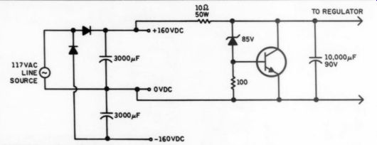
FIGURE 1: Transformerless raw supply.
NICHOLAS J. HOGYA
Willowdale, Ontario, Canada
James Boak replies:
You must remember a few basics when using any transformerless design, and then there are considerations specific to my design. Let's address both areas.
The most likely reason for failures in a circuit like this is unintended grounding of the supply due to the linkage to earth ground. A transformerless design has the disadvantage of having the rails related to earth ground. This can cause problems when connecting to equipment which uses earth ground as a safety or shield ground; you must make sure everything else in the system is free to float.
If R3 burned, I would suggest that TR5 is probably gone too. Resistor R3 can have no more than 0.7V DC across it, unless the emitter-base junction of TR5 has burned out. Once that happens, R3 is pulled to a substantial voltage and quickly burns up. This may have occurred on power-up due to a surge voltage, although I have not had any problems with supplies at much higher voltages (500V DC, for example).
The outputs of bipolar supplies are linked together on start-up through the amplifier's supply caps; it is easy to see that one rail will come up a half-cycle before the other. Depending on the amplifier's grounding scheme, this can pull the amp ground tens of volts away from the regulator's ground. With a circuit like this, TR2 and IC1 might see excessively high voltages for several milliseconds (enough to damage IC1's internal pass element). The solution is to tie the regulator to the amp ground with very substantial wiring.
Another problem with transformerless design is safety. As you probably know, a great many radios produced before the transistor era used the famous ''five tube'' transformerless layout; these radios were light, economical to produce, and reliable, but the cases, knobs, and all other external components were constructed of non-conducting materials to ensure the user did not receive a shock.
The "'ground'' in your supply is actually one side of the 117V AC line; depending on a variety of factors, this could potentially place substantial voltages on the ground side of jacks and speaker connections, with attendant safety hazards to the user.
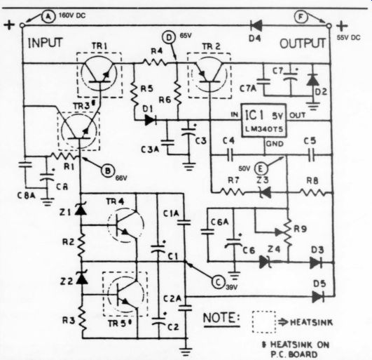
FIGURE 2: The Boak regulators altered for use in the Dynaco ST-150 and other amps.
MODIFICATIONS
------
TR1,3 MJ15022
C1, 2,3,6,7,8 130uF (200V)
3.3uF (350V) Mylar
D4 1A 200 PIV
R1 4k 5W W/W
Z2 1N4754-A (39V
Z4 1N4757-A (51V)
Assuming you have allowed for these problem areas, the layout of the basic regulator is straightforward. A bipolar transformerless supply is basically a pair of half-wave rectifiers of opposite polarity.
To provide clean power at 55V DC, the regulator must see an input of at least 70V DC minimum (this includes the glitches on the supply, so the RMS value of the raw supply is not a good indicator). 3,000uF is a little slim for the kind of power you in tend to deliver; under load the ripple voltage will increase and might affect the regulation (and the sound of the amp!).
Another problem is that the high differential across the pass element TR1 means that it will dissipate a lot of power.
At an RMS output power of 100W, about 3.5A RMS will be passing through the load. Ina bipolar system, half of this current is supplied by each regulator. If the raw supply did not drop at all, TR1 would have 95VDC across it; however, typically half-wave supplies drop to the RMS value of the input under load, heavily dependent on the capacitance at the supply output. TR1 probably has about 60V DC across it at full load. Thus TR1 has to dissipate about 100W! This is a lot to ask of a transistor rated at 150W under ideal conditions (where the case is at 25°C, for example).
One solution is to use an RC low-pass filter. You could place a 10 ohm 50W resistor between the raw supply and the load; this resistor would drop 40V DC at peak current, or an average of 20V DC at peak power, reducing the dissipation requirements of TR1. It would also smooth out the DC power supplied to the regulator.
-------
If you should have a TECHNICAL QUERY ...
about an article appearing in this magazine, write it clearly, leaving space for a reply and referencing the magazine, article and page about which you are inquiring. Enclose a self-addressed stamped envelope and send these to Audio Amateur, PO Box 576, Peterborough, NH 03458.
It is warranted, we will forward your query to the author or a Contributing Editor for a prompt reply.
Help us by not calling in your question. We have neither the staff nor the time to respond to technical questions by phone.
It will get hot, so place it with care.
I would recommend at least 5,000 uF for each RMS A of output current; you should have at least 10,000 uF at the downstream side of the raw supply, be fore the regulator.
You also could place a large boosted zener in parallel with the new cap, using a circuit like Z2-R3-TR5. Use a 150W 100V transistor, with the transistor on a large heatsink, and a zener rated at 85V DC. You could safely use 90V DC rated caps after the resister, you would protect the regulator from large transients, and you would have the additional advantage of providing smooth power. If you don't control the voltage with a zener, safe design says use at least 160V rated caps; you might get away with a lower voltage rating on the caps, if you knew what the real minimum amp loading would be.
When testing a supply run from high voltages, you should not short the output.
The various components in the pre-regulator circuit may not be able to discharge the internal capacitors quickly enough to protect IC1 from a large voltage across its internal pass transistor. Also, be sure to fuse the input of the regulator for a value near your desired RMS current (probably a 2A fuse, perhaps a 3A if you drive the amp very hard).
Given the increased complexity of the circuit with a transformerless design, and the safety hazards, would probably look hard at what the cost tradeoffs really are.
There is no reason why such a circuit could not work well, however; I would be interested to know how you make out.
Editor's Note: I strongly caution any reader who is not fully experienced in electronics to experiment with transformerless supplies. Unless your wall plugs are correctly wired, and the supply always has polarized power plugs, such devices are lethal. Transformerless appliances are still responsible for 70-80 deaths per year in the US. If you use such a circuit, include an isolation transformer.
-------------
DEMANDING DISCIPLINE?
WITH REGARD TO YOUR claim that ''audio is among the least demanding of the engineering disciplines,'' and K. E. Logan's unhappiness with this claim (TAA 2/89, p. 52), I'd like to offer an analogy which suggests a compromise between these views.
It is probably fair to say that among musical instruments, the bass guitar is one of the easiest with which to achieve a minimal level of competence. Compare, for example, the training required to obtain a passable violin tone, or to learn to play piano. However, I would suggest that to excel as a bassist requires as much skill and perseverance as to excel with any instrument; you must be as good as or better than the rest.
Certainly it is far less demanding to design a simple power amp than a personal computer, but designing a competitive power amp is not easier than designing a competitive PC, by the very nature of the marketplace. While there may be (arguably) more charlatans in the audio business, I'm sure you'll agree there are many talented and truly insightful individuals.
RALPH GONZALEZ; Wilmington, DE 19803
Also see:
A Power Supply Regulator For The Adcom GFA-555