Balanced Audio Amplifiers, By Erno Borbely.
-----------
ABOUT THE AUTHOR: Erno Borbely is employed by National Semi conductor as its training manager for Europe. He received a degree in electronic engineering from the Technical University of Norway in 1961 and worked for the Norwegian Broad casting Corporation designing professional audio equipment for seven years. He lived in the US and was director of engineering for Dynaco and The David Hafler Company. From 1973-1978 he worked for Motorola in Geneva, Switzerland, as senior applications engineer.
-----------
YOU HAVE HEARD many reasons for using balanced cables to connect various pieces of audio equipment [ 1/2/3 ] and many readers have asked me how to adapt my circuits for balanced operation. More and more high-end gear like CD players, preamplifiers, and power amps let you “go balanced ” by supplying balanced inputs and outputs. I am sure you already own equipment with balanced input(s) and output(s). If I asked how many of you are actually using this capability, however, I would probably come up with a very low number, but this is not surprising.
While in the professional audio world everything (well, almost everything) is standardized as far as connections are concerned, practically no standard exists in consumer audio. You might argue the single, shielded cable with an RCA connector at each end is the de-facto standard. This is probably true, but it certainly is not a good quality connector; its mechanical design makes it the worst possible one for audio. I know your pet version, for which you paid a fortune, does make a reasonable connection, but the RCA connector still should have been replaced by something bet ter a long time ago.
Better connectors, certainly not more expensive than the fancy RCAs, exist by the dozen. Unfortunately, it does not help that only a few manufacturers are using them; this creates confusion because you need adapters to connect audio equipment from different manufacturers. What is missing is a standard ail audio manufacturers should adopt.
Naturally, consumer audio has no standard for balanced connection. Al though a few manufacturers use other balanced connectors, more and more high-end people prefer the Canon XLR connectors. These are not necessarily the best, but the professional audio industry has used them for a long time.
They are reliable and cost less than even a modestly priced RCA, which you probably would not consider in the first place. I will go as far as saying the balanced XLR connector is better for single-ended connection than RCAs: besides its lower price, it lets you use the second conductor as a separate signal ground, alleviating ground problems. More on this later.
Unfortunately, having Canon XLR connectors on separate pieces of audio equipment does not mean you can connect them one to one. Manufacturers who produce professional and con sumer audio gear usually use the “professional ” XLR pinout, but consumer manufacturers might use a different, often reversed one. Even if you have the same connector with the same pinout, you probably do not have the cable to use between the two pieces.
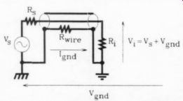
FIGURE 1: Circuit showing how the ground potential causes a current to flow in the ground wire and then a voltage drop in the wire's resistance.
Balanced cables, unlike the millions of single-ended ones, are usually not available off the shelf. So, unless the proper ones come with your equipment, you have to buy the cable and connectors and make it yourself. But you have just mortgaged your house and car to buy those beautiful, thick, single-ended cables with shiny gold RCAs on them. The store claims they are the best thing since sliced bread, so why should you buy new ones? The end of the story is you are still using the single-ended inputs and outputs of your equipment.
Where do we go from here, you might ask. First, let's consider state-of the-art high-end audio-interfacing and signal-processing equipment. A couple of manufacturers offer fully balanced preamps from input to output, including phono and line inputs, balanced signal processing inside, and balanced outputs. Others offer only balanced line inputs and outputs, the phono input being single-ended.
This, again, is not surprising: few turntables/arms can be configured for balanced output without rewiring the arm. This is unfortunate because the pickup is a balanced transducer by its mechanical design and should be connected by balanced cables to a balanced input. You could also argue that, due to low-level signals, this is where balanced connections should be used in the first place. In other audio sources, most higher priced CDs and tape decks offer balanced outputs, but I have not seen too many tuners with them.
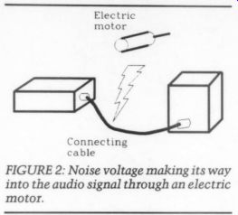
FIGURE 2: Noise voltage making its way into the audio signal through an electric motor.
I mentioned signal processing inside the preamp: this refers to the way the signal from your source (phono, tuner, CD, or other piece of equipment) is treated. Some manufacturers amplify the balanced input through balanced amplifiers, then put it through a balanced volume control and amplify it again in a balanced line amp before sending it to the balanced output. This procedure is called fully balanced signal processing.
Most preamps, however, even if they have balanced inputs, convert the balanced signal to a single-ended one, put it through a single-ended volume control, and convert it back to a balanced output in/after the line amp. This should not be necessary, but you need a four-gang volume and balance control if you wish to process your signal balanced all the way through, and four-gang pots are not off-the-shelf items. I will return to this problem later.
Even if you do not process your signal fully balanced internally, it is still worth using a balanced interface be tween pieces of equipment. Let's look at the reason for this in more detail.
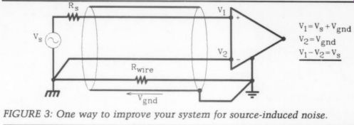
FIGURE 3: One way to improve your system for source-induced noise.
Single vs. Balanced Interface
When you link two amplifiers using a single-shielded wire, the shield is usually connected to ground at both ends- at the output of your preamplifier and the input of your power amplifier. As long as both grounds are at the same potential, this connection has no problem. The source delivers the signal at the load, maybe with some attenuation, but without adding anything to it.
In most cases, however, the two pieces of equipment have a different ground potential, usually because the power supply is tied to the chassis and the power transformer is generating a voltage through leakage. This ground potential (Voyp) causes a current to flow in the ground wire (normally the shield of your cable), which in turn causes a voltage drop across the wire's resistance (Fig. 1). This voltage adds vectorially to the source voltage and the two appear across the load as the input voltage V,. Once this noise voltage (usually originating from the power line and having a frequency of 50 or 60Hz or harmonics of these) is introduced in to the signal, it is practically impossible to remove it.
Another way noise voltage might find its way into the audio signal is through external electric or electromagnetic sources. Figure 2 illustrates the well known situation of running an electric motor next to a connecting cable. When the circuit impedances (source and load) are high (10k or more), the dominating coupling mechanism is the electric field. [2] With circuit impedances of a few hundred ohms or less, the electromagnetic coupling is the important one.
You can actually consider the shield an antenna, which picks up all sorts of noise, including RF signals, from the environment. Let's face it, our environment is, to put it mildly, anything but noise-free in electronic terms. (Think about your CD player, where high-speed digital and analog circuits are placed next to each other.) Between the source-induced noise and that picked up through radiation, it is easy to see that with many pieces of audio equipment connected, your chances of having no noise in your system are rather slim. So, how can you decrease the sensitivity of your equipment for noise? Figure 3 shows one way of improving your system from source induced noise: amplify both sides of the source and subtract them from each other at the load. The subtraction is done with an amplifier having two in puts: a plus and a minus, that is, a differential input.
This circuit works as long as the source impedance, Rg, is zero. When it is not, you will have a slight attenuation of the signal due to the finite source impedance, and total cancellation is no longer possible. Nevertheless, this is a highly recommended way of connecting single-ended sources to a differential in put. This is what I meant by using XLR connectors, where one of the wires is a separate signal ground.
To avoid this problem, you must make the source symmetrical as well, as shown in Fig. 4. This is called a balanced output, where the two signals are equal in amplitude but are 180° out of phase. The signal across the load is free of the noise generated over the shield, because a voltage drop across the wire resistance adds in phase to both inputs, which are cancelled by the differential input.
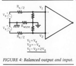
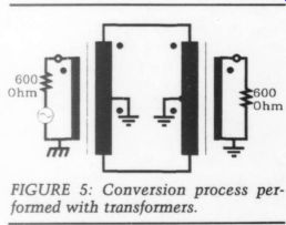
FIGURE 5: Conversion process performed with transformers.
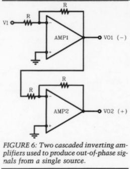
FIGURE 6: Two cascaded inverting amplifiers used to produce out-of-phase signals from a single source.
You now have a fully balanced system, much more immune not merely to source-generated noise but to noise caused by radiation. Just how much better it is depends on how well the input of the receiving amplifier rejects the noise. The noise, being in phase on both inputs, is called a common-mode signal.
The measure for how well the input is rejecting this signal is called the common-mode rejection ratio (CMRR) and is defined as:
CMRR = 20 log [A_D / A_CM]
where A, is the differential gain and Ac is the common-mode gain. Ag, is determined by connecting the two in puts of the differential amplifier to the same oscillator and measuring the ratio between the output and the input. Ideally, Ay should be zero; however, in practical amplifiers it is not.
CMRR depends primarily on the topology and matching of the components (transistors, resistors) in the input stage of the differential amplifier. Sometimes it must be trimmed with external components to achieve the necessary rejection. According to Marsh, a CMRR of 60dB across the audio range is the minimum required for high-quality equipment. Those using IC op amps have seen the CMRR specification in the data sheet. This spec is usually given at DC, and the CMRR rolls off with increasing frequency.
To be able to judge an amplifier's ability to reject RF noise, for example, it is important to know how it behaves at high frequencies. Not all data sheets specify the CMRR as a function of frequency, and not all IC op amps are equally good at rejecting common-mode signals at high frequencies.
Conversions
The above should convince you to consider a balanced interface in your audio equipment. Now let's see how single ended signals can be converted to balanced ones and back again. Figure 5 shows this conversion with trans formers, a method used in professional audio for decades and still considered the best form of signal transmission over long distances.
The professional industry is driving the primary side with a 600 ohm source impedance and is loading the secondary with 600 ohm. The cable between the source and receiver can be a simple twisted pair. You should use a tightly twisted pair in a very noisy environment. Most professional systems use a shielded twisted pair.
The advantage of transformers is that there is no galvanic coupling between source and load. Consequently, this eliminates the danger of generating a noise signal when two amplifiers are at different ground potential.
The disadvantage is the transformer itself: it is difficult to design transformers with wide bandwidth and good linearity, and they cost arms and legs.
Their double or triple shielding to avoid magnetic pickup tends to make them bulky, and they do not fit into slim-line designs easily. Nevertheless, at least one high-end manufacturer offers line trans formers for interfacing amplifiers. [1]
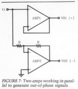
FIGURE 7: Two amps working in parallel to generate out-of-phase signals.
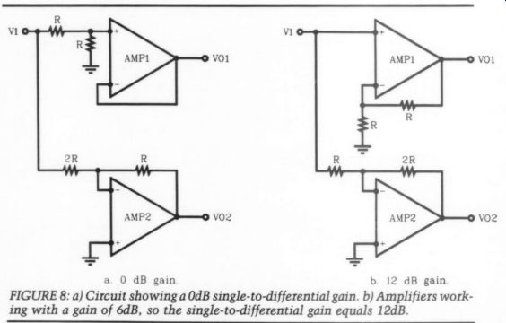
FIGURE 8: a) Circuit showing a 0dB single-to-differential gain. b) Amplifiers working with a gain of 6dB, so the single-to-differential gain equals 12dB.
If you have access to high-quality transformers, you might want to experiment with them as well. With today's technology, you can replace the trans formers with electronics, but you should remember that electronic circuits do not offer the 100% galvanic isolation of transformers.
Let's now look at how single-to differential and differential-to-single ended conversion can be accomplished with amplifiers.
Single-to-Differential
Probably the simplest way to produce out-of-phase signals from a single source is using cascaded inverting amplifiers (Fig. 6). Using equal value resistors, R, the gain to each output is unity. Because the outputs are out of phase, however, the net peak-to-peak output swing is twice that of the input. In other words, the single-to-differential gain is 2x.
Two minor disadvantages of this circuit are related to the way the amps are connected. Due to the inverting mode, the input impedance equals R, which should be kept reasonably low due to noise. Also, because the amps are connected in series, two amps are in the signal path for the positive output, which means two phase delays versus one on the negative output.
The inverting mode also offers a significant advantage: both amplifiers have a high common-mode signal range due to the large series resistors and the virtual ground input. Overall, using wide band (low-phase delay), low-distortion, and low-noise amplifiers, this scheme produces a very good balanced output.
You can use the circuit in Fig. 7 to generate two out-of-phase signals. Here, the two amps are working in parallel: amp] is a unity gain follower, generating the plus output; amp2 is a unity gain inverter, making up the minus output.
Again, both amps are working with unity gain, but because of the out-of-phase signals, the single-to-differential gain is equal to 2x. Although the unity gain follower has a high input impedance, the unity gain inverter is limited to R, so the composite input impedance is the same as that in Fig. 6.
The two amps are working in a different mode of operation: the feedback factor for the unity gain follower equals 1 (100% feedback), while the unity gain inverter has a feedback factor of 1/2, resulting in half the closed-loop band width compared to the follower. On the other hand, the unity gain follower must be able to handle the entire input voltage in its common-mode range (both inputs are moving up and down together), while the inverting amp, due to its series resistor and virtual ground input, is subjected to little common-mode excursion. Basically, using high-performance, high common-mode range amplifiers will give you a good single-to-differential converter.
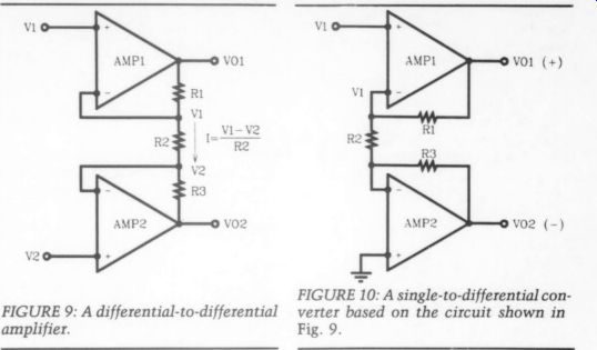
FIGURE 9: A differential-to-differential amplifier. FIGURE 10: A single-to-differential converter based on the circuit shown in Fig. 9.
You can easily implement different gain settings with this circuit. Figure 8a shows a version with a 0dB single-to differential gain, and in Fig. 8b both amplifiers are working with a gain of 6dB, so the single-to-differential gain equals 12dB. The latter circuit has the advantage of reduced common-mode requirements for amp1. All these circuits have been used as single-to-differential converters in high-quality audio amplifiers.
My preferred single-to-differential converter is based on the circuit in Fig. 9, a differential-to-differential amplifier.
You may recognize it as the instrumentation amplifier's differential input stage. The basic equations governing its operation follow: [5 ]
V_o1 = V; + (V; = V,) (R1 / R2)
and
V_o2 - Vv, = (V, oF V,) (R3 / R2) Ap - (Vor i Via) / (V, = V,)
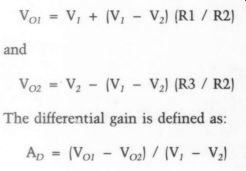
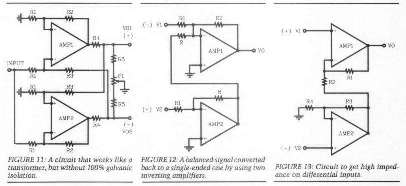
FIGURE 11: A circuit that works like a transformer, but without 100% galvanic isolation.
FIGURE 12: A balanced signal converted back to a single-ended one by using two inverting amplifiers.
FIGURE 13: Circuit to get high impedance on differential inputs.
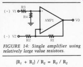
FIGURE 14: Single amplifier using relatively large value resistors.
If you let R, = R; = nxR,, then it can be shown that A, = 2n + 1.
If you make n = %, then the differential gain is equal to 2x, or 6dB. You can alter the gain by changing a single resistor: R,.
The common-mode gain is equal to 1.
You can use this circuit for single-to differential and for differential-to-single ended conversion. Let's look at it as a single-to-differential converter first (Fig. 10). Ampl is connected in normal, non inverting mode and the output voltage is equal to:
Vor = Vi ([R; + Ry) / Ry)
The positive input of amp2 is connected to ground and the amp is used as a current-to-voltage converter through its negative input. R,, instead of being connected to ground, is connected to the input of this current-to-voltage converter. This causes the feedback current from amp] to develop a second, out-of phase signal at the output of amp 2:
Voz coy -V, (Rs / R,) When R, = R;, the differential output becomes:
Vor = Voz = V; (1 + (2R; / R))) and the gain to V,, is always larger than to V,. This means amp1 is working with larger voltage swing than amp2 and will, especially with low-gain set tings, saturate earlier than amp2. If you must get as much differential swing out of the converter as possible, make the gain to the two outputs equal. You can do this by setting:
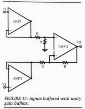
FIGURE 15: Inputs buffered with unity gain buffers.
(R, + R) /R, = R; / R,
This means R; = R; + R,. If you make R, = R, = R, for example, the gain to Vo; equals 2x.
If R; = 2R, the gain to Vo, is also 2x.
I usually put a small trimpot in series with R; so I can adjust the outputs to be identical. The documentation with the LINE388 amplifier shows this circuit as being proposed for absolute phase reversal or, if both out puts are used, for balanced output.
Although all these circuits produce high-quality balanced signals and operate properly when driving balanced loads, they are subject to malfunction under certain conditions. One such case is when you short-circuit an output or try to drive an unbalanced load. This will affect not only the shorted output, but through the feedback arrangements and other paths, it will also affect the other output. This is a faulty condition and for home audio equipment hardly a significant point. You could alleviate the problem by adding a follower to both outputs, but this would mean one more amplifier in the signal path.
In professional audio systems, line drivers with floating output are prefer able; the amp still works properly when driving unbalanced loads and, under a short-circuit condition, the other out put is unaffected. In this respect, it would work like a transformer, except it does not offer 100% galvanic isolation.
Such a circuit (Fig. 11) offers a balanced and floating output. The amplifiers are cross-coupled with positive and negative feedback, so each output signal depends on its own input and the output of the other amplifiers. Due to the cross-coupling and the use of positive feedback, be extremely careful with the frequency compensation of the amplifiers. recommend only very experienced audio amateurs try this.
Differential-to-Single
Because not all preamps and power amps have differential inputs, you might have to convert the balanced signal to a single-ended one to process it.
This is done using balanced-to-single ended converters.
One of the simplest ways to convert a balanced signal to a single-ended one is to use two inverting amplifiers as shown in Fig. 12. The positive input is inverted through amp2 and summed with the negative input in amp1. Amp1 is also operating in inverting mode.
When common-mode signals exist at both inputs, they are cancelled through the phase inversion: the one on the positive input is inverted and cancels when summed at the negative input of amp1.
The resistor matching limits the CMRR to approximately 50dB;¢ trimming can improve this significantly.
Input impedance is the same for both amps (equals R,). This can be an ad vantage from the point of view of terminating the cable. Because both amps are working in inverting mode (series resistor and virtual ground input), the common-mode voltage range is very large.
If you need high impedance on your differential inputs, then the circuit shown in Fig. 13 is preferable. Both in puts are amplified through a non-inverting amplifier, but the output of amp2 is fed into the negative input of amp1, summing it with the negative input of the source. Normally, the resistors are chosen as follows: R;, = R,and R, =
R;, which results in a gain of:
A=1+(R/R)
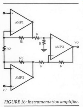
FIGURE 16: Instrumentation amplifier.
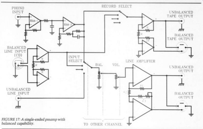
FIGURE 17: A single-ended preamp with balanced capability.
Equal value R's produce gain of 2x, but circuit also works with higher gain. In fact, this configuration is one of the simplest to drive a power amplifier differentially as you will see later.
You can have another differential-to single-ended converter with high and equal input impedances by using the circuit in Fig. 9. This time you use it with differential input, but only one output:
Vp; Although the gain of amp 2 is not important for the operation, you should optimize the circuit by selecting an equal feedback factor for the two amps (equal frequency response).
When you do not have the restriction imposed by the low-impedance feed back network or if your differential source is able to drive low-impedance loads or the gain is unity or close to unity so you can use relatively large value resistors, then the single amplifier shown in Fig. 14 is the simplest and least expensive differential-to-single ended converter. Making all four resistors equal results in a gain of 1x.
Common-mode rejection depends on resistor matching. For critical applications, 0.1% or better matching is necessary. Non-equal source impedances, however, will unbalance the circuit, reducing CMRR. You can trim CMRR by adjusting the resistor between the plus input and ground. The input impedance for the two inputs is different:
the plus input equals R; + R,; the minus input is R,. You can equalize the two input impedances by setting R; + R, = R,. To preserve the CMRR, you have to make the resistor ratios at the two inputs the same.
To avoid relatively low and different input impedances and the CMRR's dependence on the source impedance, you can buffer both inputs with unity gain buffers (Fig. 15). In this circuit, both in puts will have a very high input impedance and, because you are driving the inputs of amp3 from the equal and very low output impedance of the buffers, the CMRR can be very high.
From here, only one step remains to the instrumentation amplifier (Fig. 16), a combination of Fig. 9 and Fig. 14. With R, = R;, the gain, which is set by R,, is:
= (1 + (2R, / Ry))
Common-mode rejection is again a matter of matching the resistors, R, in amp3. You can add more gain in amp3 if necessary. Input impedance of the instrumentation amplifier is the same for both inputs and is very high.
To complete this overview of single to-differential and differential-to-single converters, I will mention some special devices developed to support balanced audio interface. Solid State Microtechnology, now part of PMI, produces a series of audio products, including the SSM-2016 differential audio preamplifier, which can be used as a balanced microphone preamp or as a differential line receiver. Ben Duncan? is proposing this as a phono input stage in his new preamp design, AMP 02.
Audio Teknology Inc. in Oregon also offers balanced circuitry: their EF 102 is said to be a dual balanced input device and the EF101 is a balanced output device, capable of driving 6009. Both are designed for professional audio equipment, like studio mixing consoles and music synthesizers. You might want to look into these devices as alternatives to the converters I have described.
Balanced Preamplifiers
As I mentioned before, some manufacturers process balanced signals as such throughout the preamp; others convert them to single-ended signals, process them as single-ended, and then convert them back to balanced signals at the output. How you build balanced capability into your system depends on whether you wish to modify an existing system or build one from scratch.
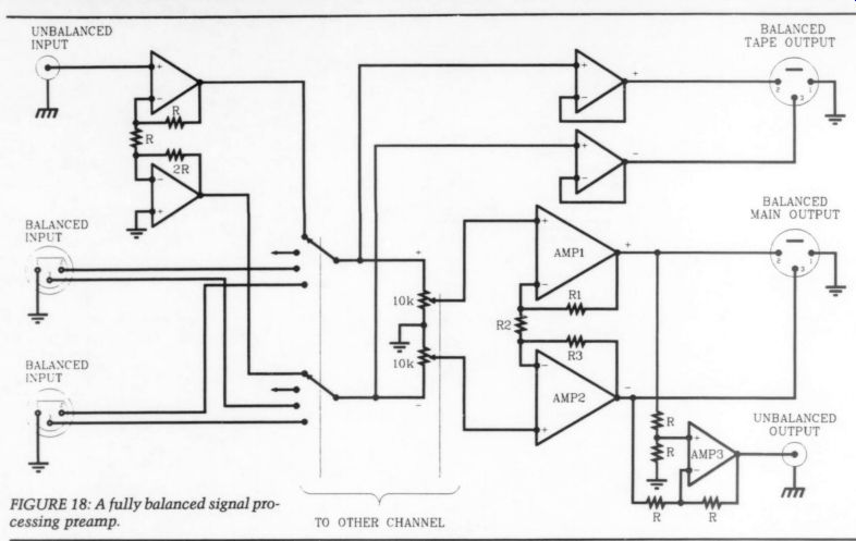
FIGURE 18: A fully balanced signal processing preamp.
A block schematic for a single-ended preamp with added balanced capability is shown in Fig. 17. To create a balanced output from a single-ended volume control, replace your line amp with one of the single-to-differential converters mentioned earlier. In Fig. 17, I have chosen the one from Fig. 10.
The positive output is available as a single output, just as before. R;, R,, and R; adjust the gain of the line amp. If you are making a preamp for CDs only, make R, = R, = Rand R; = 2R. This will give you a single-to-differential gain of 4x (12dB), which should be enough for all CDs and power amplifiers. The gain to the single-ended output is 6dB.
For normal 20dB line amps, you should use the network recommended for such an operation. The tape output has been treated the same way, with the gain set at 12 and 6dB for differential and single-ended gain, respectively. If this is too much, reduce it by approximately half by making R, = 1/2 R and R3 = 1.5R, leaving R2 = R.
This configuration is not practical for lower gain than this, so if you have to go down to, say 0dB, try one of the other converters (Fig. 6 or 8a, for example). Again, the single ended output is available as before, by using the positive output.
I left the phono input single-ended, although a pickup is a balanced device and could be treated as such. I have shown one balanced input; it is converted to a single-ended signal using the circuit in Fig. 10. You can also use the converter shown in Fig. 14 as long as you can live with the relatively low in put impedance. The converters shown in Figs. 12, 13, 15, and 16 are also applicable.
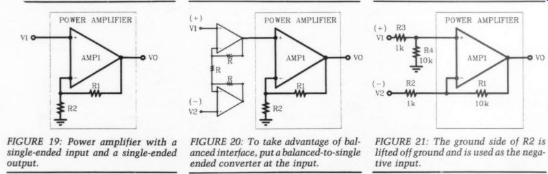
FIGURE 19: Power amplifier with a single-ended input and a single-ended output.
FIGURE 20: To take advantage of balanced interface, put a balanced-to-single ended converter at the input.
FIGURE 21: The ground side of R2 is lifted off ground and is used as the negative input.
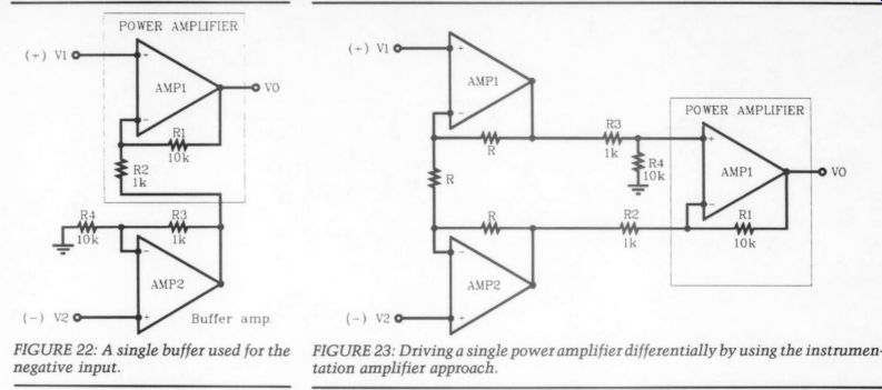
FIGURE 22: A single buffer used for the negative input.
FIGURE 23: Driving a single power amplifier differentially by using the instrumentation amplifier approach.
If you build a preamp from scratch, I suggest you go for fully balanced signal processing, as shown in Fig. 18. The line amp is a full-blown instrumentation amplifier (Fig. 16). The balanced (plus and minus) outputs are taken from the outputs of amp1 and amp2, while the single-ended output is supplied by amp3. Naturally, if you do not need the single-ended output, you do not have to install amp3. Alternatively, the positive output can be used as the single-ended output. However, you lack the advantage of the CMRR capability of an instrumentation amplifier and the gain is half that of amp3 output.
The balanced tape output is produced by two unity gain followers, although you might use the same instrumentation amplifier here as that shown for the main output. If you need an unbalanced output, use the positive output from the upper buffer.
I would expect only balanced inputs in such a system; your sources should all have balanced outputs. If they do not and it is not practical for you to build a single-to-differential converter into your source, convert it to a balanced one at the input of your preamp. This is shown in Fig. 18 for the unbalanced in put, using the circuit from Fig. 10.
Again, any of the other converters could be considered.
The major problem with balanced signal processing is the volume control: you need a four-gang one, which, al though advertised in all potentiometer catalogs, is usually not available as a standard item. One example is the Allen-Bradley Mod Pot series 70, 72, and 73, which is a multi-section potentiometer, the series 70 being a conductive plastic type. Apparently, you should be able to buy the parts and put any number of sections together yourself.
Contributing Editor Gary Galo indicated the same in Ask TAA (4/88, p. 50), saying that Newark Electronics carries these parts. have received samples from two manufacturers and have units in stock from one of them for a reasonable price.
This problem has two relatively simple solutions. One is to use two ordinary stereo volume controls, place them close to each other, and use them as if you had two mono preamps, with in dependent volume controls. One good thing about this is that it eliminates the need for balance control. I used this approach, but changed to four-gang pots when I received the samples.
The other method is to use stepped volume controls. I am especially interested in the approach presented by Joseph O'Connell (TAA 3/89, p. 33), which will also solve the balance control problem neatly. Maybe we can persuade Mr. O'Connell to come up with a balanced version of his stepped volume control.
The balanced input and output connectors used are the Canon XLRs, with the numbering shown from the wiring side. Due to lack of a standard, I have selected the pinout by the professional audio world. It is necessary that you check the pinout of the connectors in your equipment before you wire your preamp. If you do not find this information in your user's manual, check with your dealer or write to the manufacturer of the equipment.
Balanced Power Amplifiers
Normally, power amplifiers have single ended inputs and single-ended outputs (Fig. 19). If you have no way of getting inside the power amp (or do not wish to) but would like to take advantage of balanced interface, put a balanced-to single ended converter at the input.
Figure 20 shows this simple solution using the converter from Fig. 10. Try to determine the total differential-to-single ended gain using equal value resistors (R) in the converter. Naturally, you can also consider other converters for this application.
If you can modify your power amp, you will be able to optimize your circuit better. You should be able to lift the ground side of R2 off ground and use it as the negative input. This arrangement is shown in Fig. 21, which is the same configuration as in Fig. 14. I indicated certain values for the feedback network and for the input network, which can be considered typical in commercial power amplifiers.
This configuration has its advantages and disadvantages. It has non-equal in put impedances; the positive input is approximately 11k, but the negative is equal to R2, which in this case is 1k.
Your balanced source will therefore have to drive non-equal loads, one of which has a very low impedance. You can, of course, equalize the input impedances by making R3 + R4 = R2, but this does not remove the burden from your balanced line amp; now it has to drive two equally low impedances.
On the other hand, if your line amp is capable of driving such low impedance inputs, it could be an advantage because your cable will terminate with an impedance closer to its characteristic impedance. This method is used in some high-end power amps to improve sound quality! If you have built one of my power amplifiers, you might remember I have been using feedback networks with lower impedance than the one shown in Fig. 21. This is normally done to avoid stability problems caused by the input capacitance. Unfortunately, it would take quite a line amp to drive the 100 ohm I usually use for R,.
Consequently, I have looked at the possibility of increasing R, and it turns out you can go up to 0.5-1k without sacrificing performance. However, in most cases, you must readjust the stability network of the amplifier or at least optimize square wave response by re working the R-C network across the feedback resistor R,. As you probably guessed, I have tried most of my power amplifiers with a higher feedback impedance and they all work well. In any case, a line amp such as the LINE388 can drive even lower impedances, so you have a number of possibilities to 'go balanced." However, if your line amp does not like low-impedance loads and you do not wish to modify it, you can use a single buffer for the negative input as shown in Fig. 22. This is the same con figuration as in Fig. 13, amp] being the power amplifier and amp2 driving the negative input and at the same time equalizing the gain to that of the non inverting input. Amp2 will also need some phase equalization to match that of amp1.
The most elegant way of driving a single power amplifier differentially is using the instrumentation amplifier approach shown in Fig. 23. You will notice that this is an improved version of Fig. 20, where the lower part of the converter was not used. With the resistor values shown, amp2 is driving a lower impedance than amp1. This can be corrected by making R; + R, = R, as noted earlier.
The advantage of the instrumentation amplifier, as you recall, is that you can optimize CMRR by trimming R,. In fact, you would probably put a small trimmer capacitor across R; to trim CMRR at high frequencies as well. If you do not need the gain provided by amp1l and amp2, you can use two buffers as shown in Fig. 15.
Finally, I will show you a topology that is actually a differential-to-differential circuit, which should be well known to you from power amplifiers (Fig. 24). This circuit uses independent amplifiers and the load (speaker) is connected between the two hot output terminals. This is the same as operating two mono amps in a bridged configuration.
Common-mode gain, as stated earlier, is equal to 1; whatever appears at the two inputs in phase will also appear across the load in phase. As long as the load can handle the common-mode signal range, there is no problem. For ex ample, a loudspeaker cone will not move if you are driving both terminals with the same signal. Combined with the audio signal, however, the amplifiers might be driven into saturation/clip ping if you have very large common mode signals at the inputs.
Using two amplifiers in balanced mode will double the available voltage swing across the load. If the amps can also deliver twice the current, the balanced (or bridged) configuration will yield four times the power compared to a single amplifier. Remember that driving very low-impedance loads in balanced mode requires enormous current reserve from the amplifiers. I think this is where most balanced or bridged con figurations fail to produce the expected sound quality in spite of the increased power in high-impedance loads.
Amplifiers intended to work in balanced mode must be specially designed to cope with this. One way is to use relatively low supply voltage with very high current capability and double the number of output devices in both amplifiers. Naturally, you should make sure current limiting is not activated under low-impedance conditions.
REFERENCES
1. Madsen, Michael, “Sund Balance,” High Fidelity, nr. 1-90.
2. Marsh, R.N., 'Understanding Common Mode Signals,"" Audio, February 1988.
3. Duncan, Ben, “A State-of-the-Art Pre-Amplifier: AMP 02," Hi-Fi News & Record Review, October 1989, November 1989, January 1990.
4. K. Renner, Editor/Publisher of DAS OHR. Private communication.
5. Frederiksen, T.M., “Intuitive IC Op Amps, ” National Semiconductor Technology Series, 1984.
6. Cabot, Richard, “Active Balanced Inputs & Outputs,"' Sound & Video Contractor, March 15, 1986.
7. Precision Monolithics Inc. Databook 1988. OP-471 datasheet.
8. Skritek, Paul, “Schirmungen in der Audio-Schaltungstechnik, ” Franzis Arbeits buch, Franzis-Verlag, Munich, 1989.
9. National Semiconductor, Linear Applications Databook 1986, AN-31, p. 90.
10. "Equipment Profile,"' Audio, April 1990. Review of Jeff Roland Model 7 Mono Amp.
--------------------
++++++++++++++++
Also see:
A SIMPLE CURVE TRACER--Part II, By Erno Borbely