By L.B. DALZELL
ABOUT THE AUTHOR: L.B. Dalzell retired in 1985 after a long career with the Bell System, where he did mostly engineering and circuit design work. He's been interested in audio since the early fifties, and has had several articles published, starting as early as 1959 in Audio magazine. He is spending some of his retirement designing audio related devices.
---------------
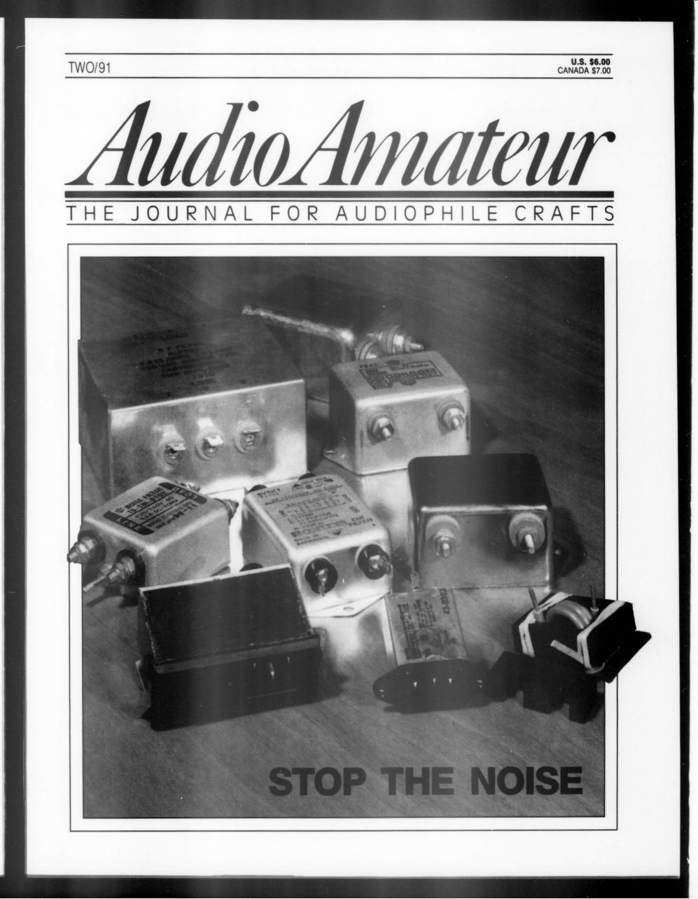
Noise IS EVERYWHERE. I've heard it said we live in a sea of noise. In our electronic world, it has become al most impossible to find a truly quiet environment. This article is about noise in sound-reproduction gear. It is not in tended to be a scientific or engineering text, but rather a pragmatic approach to the reduction of noise and the related improvement of the purity of the sound reproduced in high-fidelity equipment.
Anyone wishing to pursue the subject further should obtain Noise Reduction Techniques in Electronic Systems (second edition) by Henry W. Ott and Grounding and Shielding Techniques in Instrumentation by Ralph Morrison (Wiley Interscience publications).
I began this project when Audio Amateur's Editor sent me sample ferrite E cores and asked if I would consider using them in noise reduction and possibly developing a circuit. I looked at my notes made over the years and built three trial noise filters and a placebo (more on that later).
Going back quite a few years, we had a tremendous noise problem with vacuum tube amplifiers, preamplifiers, and other devices. Another radio enthusiast and I ran down the problem. We lived close to a US Navy radar training facility, and they had an immense shipboard antenna they would fire up frequently.
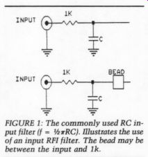
FIGURE 1: The commonly used RC in put filter (f = 0.5 pi RC). Illustrates the use of an input RFI filter. The bead may be between the input and 1k.
Almost everyone in the area got the “'buzz-buzz-buzz ” at about three-second intervals as the radar antenna went around. We eventually became experts at adding 1k resistors and a bleed-off capacitor to ground inside the chassis and back of the connectors. This technique from the early 1950s is still used today (Fig. 1).
If I may be excused for a bit of nostalgia, in that period, if you had a Garrard changer, a GE variable reluctance cartridge, a Scott or Fisher tuner preamp, and a Craftsman amplifier, an Altec 604C or a JBL 130, or even a Bozak three-way system, you were in the high end audio field.
I once tested speakers in a large re search anechoic chamber. We walked into the chamber on a wire grid, placed the gear, and my associate went out for a moment to make some microphone tests. Alone, I became aware of a hissing noise that proved to be the blood rushing in my ears. Normally, one is not aware of that background noise, but our wonderful brain allows us to ignore the background noises we have with us at all times.
Stop for a moment and examine your listening room. Is the refrigerator in the kitchen operating? Is there a fluorescent light on and its ballast humming? Is the fan motor operating with the heater or the air conditioner on? Is there traffic noise from the street? These are some background noise generators I discovered when I started examining the concept of noise.
Noise will always exist, but we can certainly reduce it to make our systems sound better. Look at a resistor handling a small amount of current. Due to the electron movement in the resistor, some noise will develop. This is called “thermal noise ” or “Johnson noise. ” Various types of noise are developed in transistors, FETs, vacuum tubes, and op amps. (Chapter 8 of Noise Reduction Techniques in Electronic Systems covers the subject extremely well.) When you perform maintenance and checks on older amplifiers, you may find the 'hot molded ”' or 'carbon stick' type of resistor. I examine these for resistance value. Wire-wound resistors have the lowest noise, but are frequently inductive and should be checked for any inductance before using. So I frequently replace the resistors with the second best choice, metal film types, to reduce noise.
That is a short coverage of the noises we can do little about. Equipment designers must have specified low noise devices and components at essential places, and manufacturers must not cut corners and use less expensive parts to meet a specific slot in the market. That is one good reason why top-grade gear is costly.
Radio Frequency Interference
Not too many years ago, TV news was covered with 16mm cameras. The film had sprocket holes on one edge and a
magnetic stripe on the other. I worked on the design of a miniature tape recording and playback unit encased in a metal box and fastened to the side of the camera.
When tested in my home shop, all was great. In a building about two blocks from an AM transmitter, however, when I plugged in the headphones and the microphone and flipped the “on” switch, I got the AM station LOUD AND CLEAR. The microphone cord and headphone cord were acting as antennas through which the RF energy was getting into the box. The input op amp was rectifying the energy, and the gain devices were handling the audio at about the same level as the mike input. By then, ferrite beads had come into the picture. Beads plus the 1k resistor and a mica bleed capacitor solved the problem (Fig. 1).
About that time we learned that the inexpensive RCA-type plugs had a possible problem if they were not properly terminated. The associated coax frequently had its woven shield opened an inch or two back and the center insulated conductor fed out at that point.
This allowed the shield to be soldered to the neck of the plug; the center conductor could then be stripped and fed in to the center pin and soldered from the end. The unshielded part, though only an inch or so, could pick up RF energy.
Two connector types have been foisted on the public: the garden variety RCA and the PC used on cameras.
Neither is very good. Today, we can get quality plugs and sockets for audio that shield the center conductor right up to the socket and that ground the shield first.
At one time, I converted all my inter connects to BNC with crimped sleeves over the insulation and braid. Later, I converted to balanced lines, using XLR plugs and sockets (more later on this).
I helped a friend with his interconnects in a good quality RG59U and F type connectors commonly used for TV. We used plugs with an external sleeve that must be crimped to the insulation and that squeeze the braid to the inner sleeve. This may cause purists to feel ill, but they still sound good.
Recall that when music and RF, or rectified (demodulated) RF, are mixed in any system, you get the basic frequencies and the sidebands out. F1 and f2 in put result in f1 and f2 out, plus the sum of f1 and f2 and the difference between f1 and f2. It can get to be a mess.
Digital equipment, such as CD players, can also cause RFI. Digital systems, even those running on 5V DC, operate on square waves, switching on and off very fast. This can, in effect, be induced as RFI into other parts of the sound sys tem. Proper shielding is a must and manufacturers have done a good job of protecting us from the hash developed in CD gear. It is also fair to say that a line filter will prevent internally generated noise from escaping on the power lead and affecting the rest of the system.
Electromagnetic Interference
EMI can really mess up the situation as it generally gets into the equipment on the power lines. This is where I will ex amine the E cores.
The power cord entering your equipment can act as another antenna path for RFI. Power sockets that include a filter circuit go a long way toward blocking the entry of noise sources. The problem is the usual one-these devices are costly, so they are usually found only in high-end equipment. It is possible to make up a filter, or purchase a commercial unit, and add other protection, all of which can make your system sound better.
When I fixed the door of a neighbor's closet that would not open after she had new carpet installed, she gave me one of her late husband's favorite toys, a big, heavy McMurdo-Silver all-band radio.
The chassis was probably steel, ascertained by a magnet check. The outer chassis and the cans (the size of soup cans) covering the tubes and the IF transformers were plated a bright nickel, while the interior of the cans and chassis were copper plated. After slowly bringing up the voltage, I was amazed the old thing worked. There was an engraved brass plate on the chassis that stated:
“Made for (name), date, by McMurdo Silver, address.
This 1930s unit was a real wonder.
The low band started about 10kHz and went to 100kHz, and it was astonishing to find the amount of radio traffic down there. Most sounded like high-speed teletype. Going up a band and using a clip cord for an antenna, WWVB from Boulder, Colorado, came in loud and clear. There are two lessons from this incident for us today. The high conductivity copper-plated interior helped drain off the interference to ground, and the amount of energy from 100kHz down could be a problem.
I should never have sold it, but a collector from Beverly Hills dropped every thing, drove down to San Diego, and offered such a good price I couldn't refuse.
When I gave the money to our elderly neighbor, she was astonished and insisted I take another toy, two rather heavy cubic boxes with vacuum tube sockets on top. They were a bit under a foot cube and were tied together with an octal socket connector. Made by McIntosh, they sounded great then and still do now.
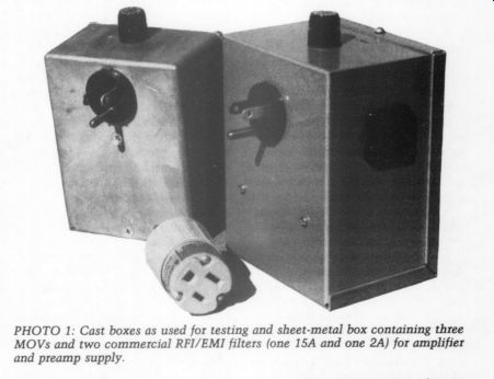
PHOTO 1: Cast boxes as used for testing and sheet-metal box containing three MOVs and two commercial RFI/EMI filters (one 15A and one 2A) for amplifier and preamp supply.
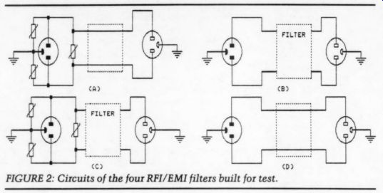
FIGURE 2: Circuits of the four RFI/EMI filters built for test.
Every power line, whether a “high line ” distribution system or the wiring in the home, radiates. A field is set up that can be detected and amplified to cause noise in any sound system.
Older homes used thin wall conduit (at least in North America), which was grounded. The power distribution wires were pulled through the conduit and the radiation was near zero.
About the early 1940s, agencies began to approve 120V distribution systems using what has been given the generic term Romex. They were insulated wires with a heavy woven cover, usually un shielded; a small gauge copper protective conductor was included in the assembly. Thus, the system could have a protective ground at the outlet, but there was no inter-outlet shield. A flex duct is available, but is more expensive.
In this case, a spiral metal cover is the magnetic shield as well as the exterior physical protection, and it can carry the ground, provided a proper fitting is used at the outlet boxes. I write about the North American situation, as I have little knowledge of the standards of other countries.
I experienced one situation that illustrates the possible problem of radiant fields. Mr. Enthusiast was an extraordinarily neat person, and the electric cords feeding the units of his system were all laid out straight and parallel with the Romex power feed. He had some audible 60Hz interference. When I coiled the cords and made a bit of a 'rat's nest,’ the noise went away. It pleased him that I had cured the problem, but it disturbed him that neatness was not necessarily an answer.
From the experiences outlined thus far, you should notice that metallic shielding and excellent grounding are musts. A renowned British maker believes any magnetic materials are to be avoided, hence his chassis and cases are made of plastic. Could be, but I wonder.
As you observe power line noise, you may be astonished to see what is happening on the AC power. Usually, a power transformer feeds a number of buildings, or homes, and all sorts of devices are fed by the power, many of which are noise makers. Many of our household devices have electric motors that draw lots of current when started and can put out astonishing pulses when they turn off. Such things as your refrigerator, freezer, and washing machine, and perhaps the neighbor's noise makers can affect your AC.
Noise Filters
Using SSRs (solid-state relays) that have 0-V turn-on and turn-off can reduce noise. When I equipped our air conditioning with an SSR, the turn-off noise was eliminated. Dimmer switches are a common cause of noise, as the sudden turn-on of the internal TRIAC (or SCR) can develop lots of RF energy.
Most dimmers have filters to protect the line from hash, but one never knows.
You can use an oscilloscope with a memory function to obtain images of the hash on the AC sine wave. Even better is a power-line disturbance analyzer, such as one made by Dranetz. It is a sophisticated and expensive device that prints out the history of the power-line performance. A tape not unlike a cash register tape indicates “sags” (situations where the voltage is dragged low for a period and “surges ” (where the voltage goes high for a period) and indicates the duration. A 'hit' or a high voltage, usually a pulse, is recorded, as is the voltage and duration.
In both cases, the time of the incident is printed on the tape. I was astonished to see about 9 feet of tape on one quiet Sunday, for I had borrowed the de vice and it had to be returned promptly on Monday morning. I performed the tests on Saturday with the AC line by itself and with the addition of a filter on an hourly basis-one hour with the filter, the next without. The difference was astonishing.
In addition to filters, protectors like the MOV (metallic oxide varistor) de vices are available.! These look like a large ceramic capacitor. Varistor means “variable resistor ” and they are voltage sensitive. When the voltage gets high, they reduce their resistance and chop off the high voltage pulse. I have made use of lots of the GE-MOV devices and the Panasonic line is now available from Digi-Key and Radio Shack.
Many commercial RFI or noise filters are also available. I found a number of sizes and types in a local surplus shop at about $2 each. I purchased several and made up some for trial as external plug in devices (Photo 1).
An Audio Placebo
In medical research, when a new drug is tested on humans, who are subject to the power of suggestion, the researcher uses a placebo, an innocuous pill or capsule, and compares the results of the test group and the placebo group.
I strongly believe in the value of what I shall call an “audio placebo. ” I constructed four test filters: Fig. 2a used only the MOV devices, 2b used a commercial RFI filter, 2c used a commercial filter and the MOV devices, and 2d was the placebo (it was wired straight through). I used three MOVs in each case to be sure. One was wired from the line to the neutral, one from the line to ground, and the last from the neutral to ground. The four devices were given to audio enthusiasts for trial and were sealed in cast boxes to prevent peeking.
The resulting ratings in use as the best were a--13%, b-25%, c-60%, and d -2%. From this, I conclude there is a validity in using the filters, especially the filters and the MOV combination.
The placebo, in this case proved its point, that something was a lot better than nothing.
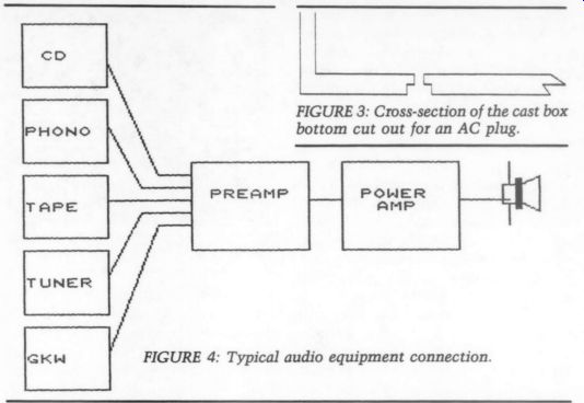
FIGURE 3: Cross-section of the cast box bottom cut out for an AC plug.
FIGURE 4: Typical audio equipment connection.
The Third-Wire Theme
I will deviate for a moment to cover one factor that can be of the utmost importance: the third wire on the cord running from the outlet to the equipment.
It is a protective ground required virtually worldwide by all the various electrical codes. In the event of failure, it ensures that the power will have a path to ground. Further, it is a path for un wanted noise to ground.
I have seen situations were the user habitually removed the third-wire pin from the plug-an idiotic practice. I have seen other situations where the ground pin was removed-as the noise dropped when the plug was reversed, which cannot be done with the ground pin in place. One investigation of this claim disclosed that the power service was wired incorrectly-the line and the neutral were reversed. In North America, the line wire is black, the neutral wire is white, and the ground is green.
Other countries use different color codes, but the ground is there.
Getting Back to Filters
Most commercial EMI/RFI filter units have a diagram and list of components printed on the can. You can duplicate the filters or design your own by winding inductors on ferrite cores and using capacitors of something more than 1.5kV and of the correct capacity value.
I used the E cores with two cores cemented together to make a figure eight after the winding was in place.
For testing, the cores may be held in position with rubber bands. You would need an inductance bridge or an R-L-C meter to verify the value of the inductor. I found that the exercise resulted in a satisfactory RFI/EMI filter, with about four times the bulk of the commercial devices. Literature is full of information on the design of filters.
I used cast aluminum boxes for the test filters. For the socket base AC plug to be attached properly, the mounting hole had to be counter sunk (Fig. 3).
This allowed the mounting spring to seat in the socket groove.
Figure 4 illustrates a rather typical audio cross-connection arrangement (GKW means 'goodness knows what').
The lines connecting the boxes are the usual interconnects, with the signals on the center conductor and the shield ties ground from unit to unit. All the boxes are AC operated, hence there are AC cords to each box.
Given the absolutely worst situation, each box could have a three-wire cord and the power ground connected to each chassis. Such an arrangement sets up the most “gosh awful and wonderful howl! ” that can be imagined for there are all sorts of “ground loops ” through the cords and the interconnect shields. Usually, manufacturers prevent this by using two-wire cords powering the input devices and the preamp.
In a normal situation, the power amp is equipped with a ground-carrying plug and the interconnects carry that ground back to the input units. In some cases, quality amps and preamps have a tie to connect ground to the chassis or to isolate that chassis, leaving only the internal circuitry grounded.
If all the equipment is rack-mounted, another problem arises, especially with a metal rack. The chassis would be tied together through the rack, possibly pro viding another “ground loop ” path. It is not uncommon to be required to insulate the chassis from the rack.
On Grounding
This brings me to my favorite ground connection, the ‘Star Ground' (Fig. 5). My schematic design tool in my computer unfortunately made the star ground look like the Maltese Cross. The idea is to have a common ground tied to the chassis at one point.
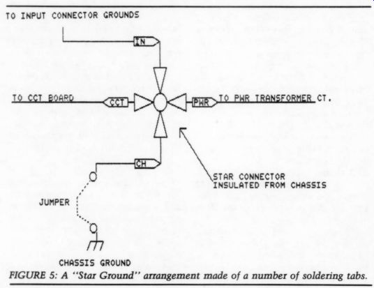
FIGURE 5: A ‘Star Ground' arrangement made of a number of soldering tabs.
Some of the better high-end amps and preamps have the chassis ground run through a jumper on the rear of the chassis, for it may be easily removed to prevent or eliminate ground loops. I used such a star and chassis ground system in the devices I have built for myself.
Input RCA jacks are insulated from the chassis and their common ground is wired and soldered to the star. In the case of the AC third-wire ground, amplifiers as I built them use the three-wire power feed. Preamps need only the two wire cord, as do tape decks, CD players, and other such devices. Record players usually have a separate ground wire to be tied to the preamp, usually the pre amp chassis.
The next step is to verify that a ground exists. One of the worst cases I experienced was finally run down to the lack of a valid ground. It was in a commercial office building and the sound system and a modern PBX went mad on occasion. We finally discovered that the building contractor had saved a few dollars by running schedule 40 plastic pipe for the water supply and had come up through the foundation with copper pipe, to which the power ground was bonded. When a new water supply was run round the building to the meter, the problem vanished.
If you have doubts, ask your electrician. Ground rods can be fabricated from reinforcing rod. Grind one end to the bare metal and solder or braze a piece of 12-gauge copper wire wrapped three or four times around the clean end and drive it in good moist soil. This should give you a decent ground.
Filter Capacitors
Many will say that anything on the power line goes through a transformer and is rectified and filtered with large capacitors, so noise cannot enter by that path. The problem is that higher frequency noise will be coupled to the transformer secondary through the interwinding capacitance. It can then go through the rectifier. The filter capacitors will not necessarily quench the noise, as their internal reactance to higher frequencies rears its ugly head.
This is another reason to use parallel bypass capacitors across the power filters.
Figure 6 illustrates the normal effect on the power supply filter capacitors.
The scope was set to 20mV per vertical division and the DC measured almost exactly 80V (an Adcom GFA 555 amp).
As a full wave bridge rectifier is used, the peaks are at 120Hz. The sine wave rises to the point where it can turn on the rectifier; the DC rises quickly and drops off a bit as the system plays (in this case, loud rock music on my grandson's CD).
Both channels were driven into Vandersteen 2SIs. The picture from the scope was on the right-side positive capacitor. The power supply filters used were 15,000uF devices. Power was fed through a Corcom filter with MOVs.
This illustrates the top of the wave where the voltage shows a slow drop of less than 10mV. It's a good power supply.
Noise Generators
As I have mentioned, the many motors around the home can be noise genera- ton, most especially when they turn off. They can cause sags in the voltage on locked rotor start (that is, starting under load), but the turn-off can be the real noise generator. I have received innumerable mild shocks from relays being released from DC-operating current.
The relay is usually well saturated and when the operating current is interrupted, the collapsing field can generate a considerable voltage, the way your car's ignition coil functions.
On the other hand, an AC-operated relay or motor can do the same thing, but it depends on where on the input wave the current is interrupted. If it is at a peak on the sine wave, the kick back can be quite large. If the AC turn off comes at or near the zero crossing, virtually no kick-back will develop; that is why a zero-crossing SSR can be a noise reducer.
In the late lamented mechanical switching telephone systems, there were literally hundreds of contact protectors; a resistor in series with a capacitor would be placed across a contact pair that operated a relay to soak up the high voltage on release. The 'kick back’ voltage can be high enough to arc back across any unprotected contacts as they open, which can add to the noise level even up to RFI. Your car's ignition coil, operated by the 'kick back’ volt age on release can generate up to 30kV pulses to arc across the spark plug gaps. Modern cars use many means to sup press the resulting RFI.
Usually, a number of homes or apartments share the same power distribution transformer, and this could be a possible path for your neighbor's noise to affect your equipment.
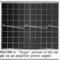
FIGURE 6: 'Scope' picture of the ripple on an amplifier power supply.
Externally induced noise from lightning is fantastic as the thunder rolls and crashes. I envy those who reside from the mid-continent to the east coast, for we are usually denied the luxury of such displays here in the San Diego area. One night when we were exposed to this massive display of the power of nature, I got up and turned on my audio system, which was fed power through a MOV / filter combination device, and it was quiet. Then I went to the garage where I have an unfiltered mid-fi test system that proved to be reacting to the lightning quite noticeably. When I plugged in one of the test filters, that system also became quiet. Removing the filter proved its efficiency, for the noises came back immediately.
Protection Devices
In both cases, I used units with commercial RFI/EMI filters and MOV devices. MOVs do a great job, but if they must shunt off any direct ultra-high voltage, either the MOV or part of the device will be effectively destroyed. When that hap pens, the strong odor it gives off usually tells you the MOV should be replaced.
Spark gap protectors are also available. They look like small glass tubes with metal end caps and radial lead wires. My Siemens catalog shows them, but I have not been able to obtain any for test. According to the catalog write up, they are not subject to destruction in use. Like MOVs, they take a tremendous current surge, about 5kA for more than 200 fast pulses.
Commercial RFI/EMI filters are available on the surplus market and are listed in the EEM books, as well as from Mouser, Corcom, Potter, SAE, and some Japanese sources. They come in many current ratings, such as 1, 3, 6, 10, and 15A. I selected units to handle the expected current of the device or system they are feeding.
Performing surgery on a few units, I discovered that usually “donut ” cores were used, and they frequently had two windings per core, properly poled so they aid in the suppression of fast rising pulses. They are usually marked EMI filter, have the Underwriter's Lab symbol of approval, and often have other symbols like the VDE and many other national lab approvals. Some include the now standard three-wire socket or a fuse holder; others are made for chassis power input mounting or are designed for internal mounting.
While you can make up a filter that will give very satisfactory results, it is preferable to use commercial devices, especially if you can find them in surplus. However, new units are well worth the cost. The makers of quality instrumentation use RFI filters almost as a matter of course.
The popularity of computers has resulted in a number of protective devices now common on the market. Most use MOVs, and frequently only MOVs, be cause high-voltage pulses can wipe out an expensive computer. Some, like the power strip that Radio Shack sells, include a MOV and inductors, and per form their job quite well.
Voltage Regulators
In many places, the power at the wall outlet is subject to voltage variations from brownouts to sags and surges. Certain voltage regulators correct line variations. These are automatic devices that regulate in various ways.
For years I used an old General Radio regulator in my shop. A vacuum tube circuit sensed the voltage out and con trolled a large VARIAC that raised or lowered the voltage in a very few cycles.
With a lot of work, I converted the control circuitry to solid state. There was one big advantage to this old unit; it put out undistorted sine wave voltage, whereas many of the other types resulted in distorted waves that could do all sorts of peculiar things to instruments and sound gear.
Lately, I have experimented with several regulators. SOLA has made such devices for years, using large trans formers, a bank of capacitors, and some fed back windings. Some are designed for a constant heavy current load; with lighter loads, the output can be too high (for example, one tested 131V out with a 3A load). Other models will output 120V AC with from 90-130V input. I check them with a lamp-bank load to be sure.
A different device is one I found from Topaz? in San Diego. This looks like a brownout protection device; it put out 120V AC, with 120 in. When the voltage was reduced with my big VARIAC, the output decreased about 6V then jumped back to the 120. It did this in four steps, o you could have a sag of about 24V and maintain good regulation.
This unit weighs about 60 pounds and consists of a large transformer and a couple of circuit boards with ICs and what appear to be TRIAC devices. Both de vices showed considerable noise reduction in the audio system possibly due o the large transformers used. How ever, the regulator transformers set up an obnoxious hum; for my purposes, I would locate it in another part of the house.
In April 1990, Stereophile published “Tice Powerblock AC Power Line Conditioner and the Titian Energy Storage System. ” The conditioner runs $1,250 and the associated energy storage unit $1,000. The power block has switches o allow you to adjust the voltage out put within limits, and the device evidently did a good job of absorbing noise and spikes. The addition of the energy storage unit allows the power line to ride over momentary sags and surges.
Longer term variations would be served by a proper voltage regulator. The regulator and an RFI filter can both be in series in the power circuit. Using the RFI filters and appropriately using a voltage regulator can give much the same result as that of the review of the Tice devices. Remember that the out put of the regulator must be an undistorted sine wave.
Interconnection
The usual interconnect (Fig. 7) is a form of coaxial cable with appropriate end terminations. Frequently, you see woven braid shielding, and this sort cannot be a 100% shield. However, it usually is sufficient for the purpose.
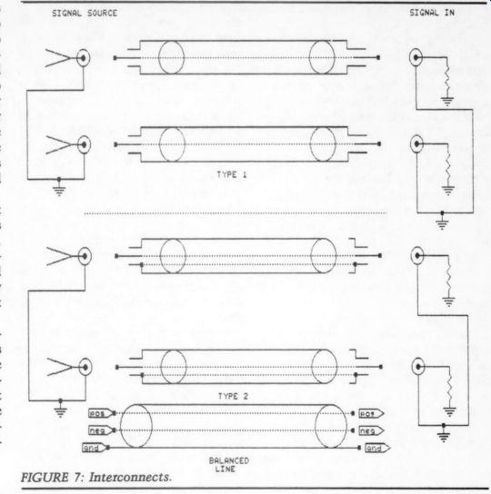
FIGURE 7: Interconnects.
A “served ” or wrapped shield uses a group of fine wires wrapped around the inner conductors' insulation. This is of ten superior to the woven shield, but gaps can develop in the shield due to movement. Belden claim their Beldfoil is the only 100% shield. This uses a metalized plastic as the shield with a drain wire for ground continuity. Other companies now make foil shield types of coax.
Looking through the wire-makers' catalogs, you discover that the inner conductor can be a single copper wire, a single copper-clad steel wire, stranded copper, or stranded copper-clad steel.
Make up sets of 1 meter length inter connects using the best plugs you can get and then compare wires, using some means of identifying them so your listeners cannot tell what the wire is.
Recently, in a British magazine, it was noted that the largest markup over cost was in the exotic interconnects, of ten as much as 100%. You can't blame the shop for pushing the $700 per meter pair wires, when the profit is $350.
That's as much or more than he can make on some of the exotic amps.
Silver is the best and finest conductor of electrical signals. It is expensive compared to copper, even high-purity, oxygen-free copper. Silver is coming to the fore in quality interconnects, and it is reputed that silver oxide is as good a conductor as metal.
Another interconnect uses two wires, one for signal and one for ground, and frequently the shield is only terminated on one end. This idea is to prevent the shield from carrying signal current or return current, and it is amore costly system.
The third idea is to use balanced line outputs. [See Erno Borbely's 'Balanced Audio Amplifiers,’ TAA 1/91, p. 15.] A preamp can have balanced outputs, for example, and the output can be de rived from tubes, transistors, or transformers. (Don't scoff at transformers. Properly designed and manufactured transformers can be as fine a high-fidelity component as any other.) In the past, and even today, you hear sounds that are run through transformers and they can be great. The old Western Electric “repeat coils' are an example of excel lent transformers, when properly used, and they could be had matching all sorts of impedances.
Balanced line interconnects, terminated with XLR plugs and sockets, are, in my opinion, the best you can get.
Swiss-made XLR connectors are avail able with gold-plated pins and sockets and anodized black shells. XLRs have good large pins and sockets, and the ground makes first. You will tend to find XLRs on professional gear.
The big advantage of balanced lines is that the balanced output signals are 180° out of phase. Thus, the two conductor fields cancel. Also, any longitudinal noise pickup is common to both conductors and the receiving device usually has a very high common-mode rejection. An outer shield is used to carry the ground, as well as shield the inner conductors. Twinax cable and connectors are available, and the connectors are not unlike the BNC type. However, I prefer the XLR connectors for their ruggedness, ease of termination, and good ground shield.
A simple pair of op amps can be good balanced line drivers, or an old “split load' inverter using a vacuum tube.
Drive the grid from a mid-point and with equal resistance on the plate and cathode, you will realize out-of-phase signals. However, the output impedances are different, the plate higher than the cathode.
Many transformers (repeat coils) have a center-tapped winding that can be grounded to leak off any induced potential from the leads. The only problem with quality transformers is size. They are usually large for most uses, but I have used some microphone transformers that were most satisfactory.
I see no reason for not using RFI/EMI noise filtration, provided your equipment does not already have such features. Even though the improvement may be marginal, the peace of mind makes the inclusion of even the least expensive device worthwhile.
At my home, the utilities are all underground, except for the distribution transformers on the power grid. You can obtain a “plug-in ”' protection device to go into the wall socket; these usually have a MOV and sometimes a thermal breaker. About 1 ” by 1% “ in diameter and a couple of inches long, the feeder cord now plugs into end. I found these at Radio Shack and at Electrical Supply houses, and they cost less than $10.
Technical Precautions
The following are offered for those who wish to construct their own filters or who use 'surplus' devices:
1. FCC docket 20780 and VDE 0871 cover the requirements that RFI/EMI filters must meet. VDE is the West Ger man standards organization, and is usually much more stringent than our UL standard.
2. FCC requires the filters to be tested up to 1.5k; VDE tests at 2.7kV.
3. The filters normally require some specific low impedance to meet design characteristics. Usually 50 ohm in and out.
4. As the filters use capacitors to ground, safety due to leakage becomes a problem. About 5mA maximum is usual for instrumentation, such as sound gear. (Medical uses require lower values-0.1mA.) In the case of surplus filters, I tested all the devices I purchased for leakage. A current meter inserted in to the ground lead back to the wall socket worked well for me. I discarded one that obviously had been taken from working equipment. Any testing over 0.5mA were suspect.
5. Multi-section filters have a broader insertion loss. They sometimes include a resistor to discharge the capacity from line to neutral.
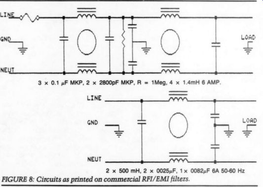
FIGURE 8: Circuits as printed on commercial RFI/EMI filters.
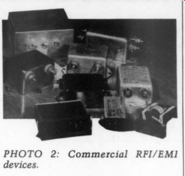
PHOTO 2: Commercial RFI/EMI devices.
My favorite radio program is ‘Car Talk' (PBS: Tom and Ray Magliozzi; usually Saturday mornings). To paraphrase the “Car Guys ”: You should have been doing something worthwhile, but instead you read this. I thank you.
REFERENCES
1. As the RFI/EMI devices are true filters, the addition of a MOV or MOVs ahead of the filter could possibly affect the characteristics.
This is due to the fact that MOVs are a bit capacitive (about 2,000pF). I have habitually run a frequency check on the filter (using a 50 ohm source and a 50 ohm terminator on the out put) then added the MOVs and rerun the frequency. Any changes are usually minor.
2. The TOPAZ device is called a “Line Conditioner. ”' It includes regulation, protection, and noise reduction filtering. Hum is specified at 40dBa maximum.
SOURCES
Filters and protective devices (see EEM section 2700):
Corcom Inc. 1600 Winchester Rd. , Libertyville, IL 60048
MCG Electronics Inc. , 12 Burt Dr. , Deer Park, NY 11729
(a comprehensive line of filters and protective devices-$50 to many thousand)
Radio Shack
RTE Aerovox, 740 Belleville Ave. , New Bedford, MA 02745
Siemens Components Inc.
Special Products Div. , 186 Wood Ave. S. Iselin NJ 08830
(MOV devices and transient/surge protectors)
Square D Company, Power Protection Systems, 9192 Topaz Way San Diego, CA 92123-1165
(power line conditioners and regulators)
--------------------
++++++++++++++++
Also see:
A SIMPLE CURVE TRACER--Part II, By Erno Borbely