AN ACTIVE INVERSE RIAA CIRCUIT, By Dmitri Danyk and George Pilko
--------
ABOUT THE AUTHORS:
Dmitri Danyk graduated from the Kiev Poly technical Institute in 1985 with a degree in electronic engineering. In 1988 he joined the Institute of Physics at the Ukrainian Academy of Sciences, Department of Solid-State Electronics, where he is engaged in research in the field of designing electronic scientific instruments. He also worked as a sound reinforcement engineer with one of the Ukrainian rock groups.
George Pilko graduated from the Kiev Poly technical Institute in 1972 with a degree in electronic engineering. In 1984 he joined the Institute of Metallophysics of the Ukrainian Academy of Sciences to design electronic equipment for tunneling spectroscopy, in particular in superconductor-insulator-superconductor systems. He has more then ten publications in the field of electronics.
----------
A PHONO PREAMP is an important part of the home audio channel. It has to meet many requirements, such as accurate RIAA frequency response, low distortion, and low noise. The following approach is widely used for testing the preamp, when the signal generator feeds it through the circuit with an in verse RIAA frequency response.
Several such circuits have been reported in literature; Lipshitz, Lipshitz and Jung, and Baxandall have suggested passive circuits and Lipshitz proposed one based on inverting an op amp with an equalization network between the input and the summing point. These circuits have several disadvantages:
They are frequency-dependent attenuators; time constants are deter mined by circuit components and by load and source impedances, which hold constant for small frequency response errors. The capacitive loading on the network output (cable and preamp in put capacitance) lead to HF errors. When
you choose low source and load resistances, this becomes negligible and a low-impedance buffer is necessary. You should isolate the input of the active inverting preemphasis circuit! from the signal source in the same manner.
When you proceed to calculations, one component determines several time constants, so its value will be defined after several iterations. The result will not be in accordance with standard series values (E24 for capacitors).
They cannot be used in various intermodulation tests.
Topology
The inverse RIAA active circuit schematic (Fig. 1) consists of the summing inverter (IC1), switching low-pass filters (IC2, IC3), the output amplifier (IC4, IC5), and the output network. The summing inverter has three inputs for signals (three sinusoids in the IEC TDFD test, two sinusoids in the SMPTE and CCIF IMD tests, a sinusoid and square wave in various TIM tests, and so on).
Low-pass, second-order Bessel filters have cut-off frequencies of 20kHz for IC2 and 10kHz for IC3. They are needed for natural roll-off input spectrum simulation and for reducing the peak-to average level ratio in tests with square wave inputs (for example, “TIM 20 for phono preamplifiers ”). We chose the Bessel filters due to their flat group-delay response, so the output is free from over shoot at the end of transient spike in tests with square waves.
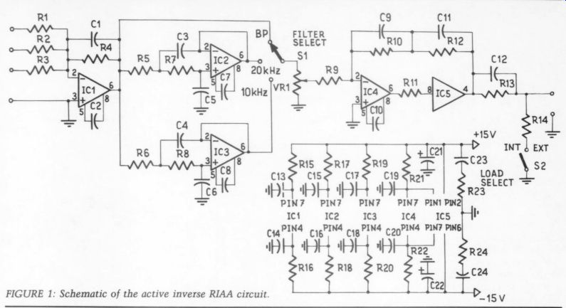
FIGURE 1: Schematic of the active inverse RIAA circuit.
The output amplifier consists of an op amp (IC4) and a unity buffer (IC5) for large output current capability. Time constants of the feedback network are:
R10 x C9 = 318uS and (R10 x R12) / (R10 + R12) (C9 + C11) = 75uS
At first, we used the wrong formula (R12 x C9) for a 75uS time constant.
This led to a -1.8dB error at HF.
The output network has time constants of R14 x C12 = 0.75uS and R13 x C12 = 3,180uS. R14 is 50 ohm to be matched with the input resistance of the coaxial cable and is sufficiently lower than MM cartridge DC resistance.
These time constants determine attenuation to be equal (-40dB at 1kHz) in maximum level position.
The output network operates correctly when an external or internal (R14) load is present in the circuit. When you use a long coaxial cable, put the external 50-ohm load on the end of the cable and open switch S2 to the left. This topology produces low distortion due to large loop gains in the op amps (unity HF gain), absence of common-mode input voltages in IC1, IC4 (inverting configurations), and DC coupling. The sidebar lists the performance data.
Testing
To measure the RIAA de-emphasis ac curacy of a preamp, feed its input directly from the inverse RIAA circuit. For other tests, insert a cartridge or its electrical equivalent between the in verse RIAA circuit and the preamp (Fig. 2). This emphasizes the nonlinearities in the input network. For example, THD in op amps without cascode in the input stage (TL071) amounts to 0.5% at HF when measured with the cartridge equivalent. Voltage-dependent capacitance between the gate and drain (or base and collector) transfers into the input network by the Miller effect and causes higher nonlinear distortions with a greater source impedance.
--------------
PERFORMANCE DATA
All measurements were made from the output of IC5, with an output level of 7V RMS. CCIF and THD distortions were measured by a frequency analyzer with a twin-T input notch filter, tuned on fundamental for increasing the equipment dynamic range.
THD
0.002% at 100Hz-10kHz
0.003% at 20kHz
0.004% at 40kHz
When measured at the output of the inverse RIAA active circuit, these values increased by a factor of 2.5, due to the output network filtering
CCIF Intermodulation Distortion =< 0.002% below the measurement floor, limited by the frequency analyzer residual.
Dynamic Intermodulation Distortion (DIM 30) =< 0.02% below the measurement floor, limited by the even-order distortion in the generator square-wave output.
Slew Rate 16V/uS
--------------------------
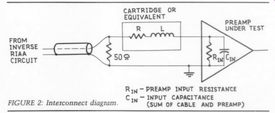
FIGURE 2: Interconnect diagram.
---------------
TABLE 1
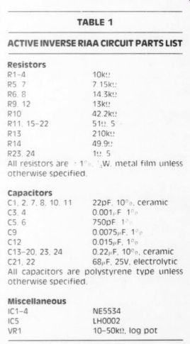
ACTIVE INVERSE RIAA CIRCUIT, PARTS LIST
Resistors
All capacitors are polystyrene type unless otherwise specified ceramic
--------------
The inverse RIAA active circuit presented here lets you perform many tests on phono preamps. Due to this circuit's wide frequency response, you can also examine the susceptibility to RFI from AM.
You can perform subjective A/B testing by feeding a CD signal through the inverse RIAA circuit and preamp in one channel and a dry CD signal in the other channel of a home audio system.
After matching polarity and level balance (by VR1) between channels, you can hear the preamp's influence on sound quality. For a more realistic situation, insert a cartridge with a specified load capacitance or its electrical equivalent. Bear in mind that such a connection leads to changes in program material frequency balance because the cartridge mechanical system does not affect the output signal.
ACKNOWLEDGMENT
We are grateful to Stanley P. Lipshitz, who read the manuscript and suggested several substantial changes and pointed out the error in the location of the 75uS time constant.
REFERENCES
1. Lipshitz, S.P., 'On RIAA Equalization Networks,' JAES, Vol. 27, No. 6, June 1979, pp. 458-481.
2. Lipshitz, S.P. and W. Jung, 'A High Accuracy Inverse RIAA Network,' TAA 1/80, PP. 22-24.
3. Baxandall, P.J., "Comments on RIAA Equalization Networks,” JAES, Vol. 29, No.
1/2, January/February 1981, pp. 47-52.
4. Holman, T., 'Phonograph Preamplifier Design Criteria: An Update, ” JAES, Vol. 28, No. 5, May 1980, pp. 325-330.
5. Schwartz, A., "The Phono Cartridge Electrical Output Network,' Audio, Vol. 65, No. 3, March 1981, pp. 26-29.
--------------------
++++++++++++++++
Also see:
Balanced Audio Amplifiers, By Erno Borbely