IMPROVING POWER SUPPLIES
Most ‘GARDEN VARIETY ’ power supplies in too many audio de vices are far too ‘soft ’ to provide the best sound. These soft power rails, that is, power supplies, have high source impedances that cannot supply ‘stiff, ’' regulated DC voltages to circuitry, especially at low frequencies.
For example, consider what happens if a series resistor is added to a well regulated supply. The resistor is terminated by a capacitor, usually too small for the demanding circuitry. The musical frequencies are thus imposed on the B + or B -rails, but shifted by 90° due to the ‘terminating ’ power supply capacitor, making the PSRR (power supply rejection ratio) small. At 25Hz, it's twice as severe as at 50Hz, this being twice as bad as at 100Hz, and so on.
Modification Tips
The signal will decrease by 6dB/octave as frequencies rise. This B+ error signal will mix with the true signal.
The resistor is usually added to lower supply voltage, to provide supply isolation between amplifying stages, or to limit turn-on current to the regulator.
For these reasons, I don't remove the resistor, but my modifications consist of increasing the size (value) of the terminating capacitor. You could use an additional regulating circuit; however, I prefer capacitor multiplication.
One way to check for this problem is to feed the circuit with 25Hz and probe the rails for 25Hz AC. This should be better than about -50dB (0.3%) of the signal on the DC rail sup plies, as compared to the active circuitry fed by that rail. I use various unity-gain processors, including 12-octave EQ devices, which exhibit this problem, including the out put-analog stage of my FM tuner. Pre amps also usually have this problem; typical circuitry will resemble that in Fig. 1.
As I mentioned, I would leave the 100-1 k-ohm resistor intact, but increase the 100-1,000uF capacitor value until the contamination signal is at least -50dB, as compared to the AC signal.
This is done at 25Hz for worst case. I do not recommend doing this in solid state power-amplifier circuitry. You might change the existing capacitors for delay timing (startup) and the like, and a modification could cause thumps or blowups.
Modifying the C-9
I modified a C-9 hologram generator that had only two stages of R-C net works-no regulation (Fig. 2). I left the original 1,000/16V capacitors intact, but ran tap-offs (from underneath the circuit board) to the right side of the chassis which has about 5” of blank space. I used a couple of 6,800/16V capacitors, making the total 7,800uF/16V per rail. You could use values up to 10,000uF.
You should increase the 1/4W, 100-200 ohm resistor to 0.5 Watt. Other C-9 units have different resistor values. The original 'contamination' voltage is -36dB, with 1V AC (at the unit's out put jacks). Increasing the 1,000uF to 2,000uF produces a 6dB improvement (to -42dB); increasing it to 4,000uF provides another 6dB (to -48dB) and making it 4,700 (minimum) would be about - 50dB. If the value was 8,000uF, it would be -54dB, and so on. Low bass is improved, but I noted the greatest difference in the mid-bass (50-200Hz).
The C-9 board is not easy to remove.
--------------
ABOUT THE AUTHOR: Roger Floth has five children and has worked in industrial-electrical/electronics for 27 years. He became interested in hi-fi about 1965 and loves to modify systems, especially bi- and tri-amped ones.
----------------------
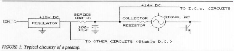
FIGURE 1: Typical circuitry of a preamp.
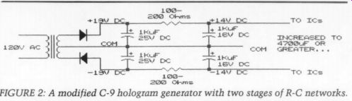
FIGURE 2: A modified C-9 hologram generator with two stages of R-C networks.
-----------------------
You must squeeze the rear cord grip with pliers, then pull it out the back a bit to let the rear of the board clear when you lift it out. First, you must loosen the light from the front panel by removing the silicon sealer. Since there is little clearance below the board, you should route the extender wires flat along the bottom so the feed-through components don't puncture their insulation. I inserted a plate of thin card board to protect the new wiring. You can mount the added capacitors on the right side of the chassis.
Other Units
Another component I reworked was the Mitsubishi DA-F20 FM tuner. I replaced C315 (100uF/16V) with a stand-up capacitor from Radio Shack (1,000uF / 16V), which supplies the multiplex chip. The two output stages had 100uF/ 25V capacitors at C403 and 503. I re placed them with stand-up Radio Shack 1,000/35V DC capacitors--all front center. The 35V caps should have insulation sleeves of about 0.25” on their leads to extend the capacitors above the board. Mark capacitor polarities on the boards before you remove the originals and replace them with new capacitors.
I also reworked the JVC SEA-R7 (with stereo reverb), a 12-octave band per channel stereo equalizer. Only the reverb needed mods. I increased C810 (100uF/16V) to 2,000uF/16V by paralleling two 1,000uF units. The maxi mum you should use is 2,200uF. The series 100 ohm resistor feeding these capacitors is a 1/4 W fuse link (R808). Too much capacitance will cause the resistor to overheat when you turn it on. If this blows, the reverb chips will not get power. I use 4,000 uF, but it gets hot quickly, then cools down quickly. An other in the reverb section is C811 (100pF/16V), which I increased to 1,000 uF/16V. The series resistor (located on the bottom board-center to ward the rear) is R809, 680 ohm. This one does not heat up. The improvement this mod made was very noticeable.
The final unit I worked on was the Onkyo P-303 preamp. I removed four 100uF/50V DC capacitors in the ‘equalizing amplifier' (MM phono-stage): C145, 146, 153, and 154.
I replaced these caps with stand-up Radio Shack 1,000uF/35V DC, as supply rails are 33V DC. These stabilize the front end, especially 25Hz, where the preamp RIAA circuitry is boosting +20dB at this point. In these cases, the series resistors are R151, 152, 157, and 158, each 10 k-ohm.
On this mod, phono was a bit cleaner in the bass. I didn't modify the MC section as I don't use it. These would be C111, 112, 115, and 116 at 1,000uF/10V DC. You could use 6.3V DC capacitors since rails stay under 3.5V DC. You could increase values to 6,300uF or so.
Series resistors are R133, 134, 137, and 138, each 4.7 k-ohm (1W). If you change them, you must also change the MM section, as the MC stage uses the MM stage's RIAA network.
Other units can be modified by ordering the respective service manuals. I also have a DBX-120X sub-synthesizer, which needed no mods.
++++++++
Also see: