- Intro
- Editorial: Thanks for the Flood
- ASK TAA
- AUDIO AIDS
- RECORDING REVIEW
- EQUIPMENT REVIEW
- BOOK REVIEWS
- JUST LOOKING
- LETTERS
INTRO
With the desire for a better method of amplitude response correction, Reg Williamson, with the help of Alan Watling, devised a new control preamplifier. In this installment , they describe the amp and how it works.
Since commercial remote control devices do not penetrate cabinets or other structures, Christian Svanberg built a device that accomplishes that function. To discover how his ‘slave ’ works, see this page.
All too often, power supplies are too soft to provide the best sound. Consequently, Roger Floth overcame this problem with his improvements for several devices. His modification tips begin here.
As an aid to repairing or calibrating monitors, Stuart Ball describes how to build a circuit that will generate a test signal for the video input to a monitor. Read about his test generator here.
Also in this issue you will find Andrea Clark's review of Stereophile's recording of 'Intermezzo' , as well as Gary Galo's review of Johnson Electronics Laboratories' AX 100 auxiliary selector and AX 101 CD-to-phono input adapter. See below ...
Editorial
Thanks for the Flood
In mid-September I wrote to all active subscribers to our three audio-based magazines asking for your help. The only term I can possibly use to describe your response is WOW! A really startling percentage of you responded within hours of receiving our call for help. I cannot possibly tell you how much it has meant to me personally. I have walked around the office for weeks feeling exceptionally humble.
Many of you have responded with personal letters expressing your support. I only wish I might answer each one individually. Some of you not only re-subscribed for two or more years, and/or ought back issues and books, but some sent checks as cash contributions in addition. I have returned these with thanks. I take all this to mean your enthusiasm for our common enterprise-which is how I see, and have always seen-these magazines. If I ever had any doubts about the sense of loyalty and mutual trust which we share as a group, those are more than dispelled.
The most moving response came from a lady who en closed a check for our four Audio Anthologies. Her letter read, in part, 'I am sorry to report that my husband passed away four months ago but he loved your magazine so much that I am sure he would want me to respond in this way.
I plan to give these books to our local library in his memory. I learned later that our departed reader's subscription was still current and his widow had not cancelled it, passing the copies of each issue on to the library. It is difficult to feel worthy of such loyalty.
I am not alone in my feelings. Your action has given every employee of the Audio Amateur Publishing group a sense of your affirmation which I believe strengthens and confirms their own job satisfaction. Their own spontaneous response is reproduced below.
I am pleased to tell you that our bankers have given us a firm vote of confidence and expressed admiration for the kind of performance throughout the past 12 months which your day-to-day business has made possible. We have had a small percentage of income shrinkage, but our new enter prise, Elektor is almost exactly on our projected target. To have achieved this result in a year of severe recession they found impressive.
I believe your confidence calls for a new course of action for us now, however.
We have set plans in motion for major expansions in our overseas sales of subscriptions. We are also laying the groundwork for new efforts in finding new audio amateurs, new speaker builders and new glass audiophiles. Nothing can insure the future and health of these three unique magazines better than larger circulations.
I have asked much from you over the recent months, and you have responded handsomely. But will you, seriously, give some thought to the people you know who could possibly become hands-on audiophiles? We will be announcing some new tools to help introduce newcomers to these unique avocations which we enjoy. But no brochure, book, or video can manage such missionary work nearly as well as areal, live enthusiast. It still strikes me that women are, in general, missing out on the pleasure of making better music by making or modifying the equipment which re produces it.
Nothing convinces like a good demonstration. Your sys tem is the bait a new audiophile convert needs to begin thinking about better sound at home. No, I am not suggesting Audio Amateur parties, but your pride in your sound system and your enthusiasm for the pleasures of building it, are the most powerful attractants for finding new audiophiles who build their own.
I thank you for your wonderful response and your care for this enterprise. I thank you as well for your extraordinary response to our advertisers which has provided a solid basis for their use of our magazines as an advertising medium.
All of us are more committed than ever to bring you the best magazines we can and to enlarge their reach to put them on a firm economic footing for the future.
-E.T.D.

FROM THE STAFF THANK YOU ALL!
For the letters, encouraging words and support.
Warm regards,
The folks at AAP and Old Colony.
Ask TAA
By Gary A. Galo Contributing Editor
POWER WEDGE II
WHEN TAA 2/91 ARRIVED, I was pleasantly surprised to see not one ('Ask TAA’) but two articles on power line noise.
L.B. Dalzell's article ‘About Noise ’ was an education. It's required reading for anyone interested in power line noise (and everybody who owns an audio sys tem should be). Recently, I discovered an article in the June 1991 issue of Recording-Engineering-Production called ‘Audio Noise and AC Systems-The 2-phase solution to a difficult problem ’ by Martin Glasband. As most readers know, our AC power system in the US is an unbalanced system. A grounded power outlet has three conductors: hot, neutral, and ground. Back at your circuit breaker box, ground and neutral are tied together. (A properly wired electrical sys tem shouldn't have more than 1V RMS potential between ground and neutral.) Our AC 120V distribution is an unbalanced transmission system with two grounds. In most American homes, only two appliances operate from balanced power lines: the stove and electric clothes dryer. These 240V appliances are fed by a pair of hot 120V lines 180° out of phase with each other, resulting in a total of 240V RMS potential between the two lines. The third pin on the large 240V outlet is, of course, ground. Mr. Glasband makes a convincing case for balanced 120V AC power and discusses Zoo Studios, a new recording facility wired with a completely balanced AC system. He concentrates on benefits even those without the auditory equipment necessary to perceive non-MAAD differences can appreciate. Not long after the studio opened, a musician who used a Fender guitar amplifier that hummed most of the time was surprised to find his amp silent when powered by Zoo's balanced AC system. But, the article has implications going beyond the reduction of such obvious noise problems.
Dedicated Wiring Over the summer I redecorated our living room, including new paint, base boards, and carpet. While I had the room torn apart (two weeks without my audio system), I ran five separate, dedicated power lines for my audio equipment.
Each outlet has an uninterrupted (no junction boxes or splices) 12AWG line back to the breaker box. I used Leviton 20A outlets, since they make a much tighter contact than the normal 15A variety, and applied Cramolin R-5 contact cleaner to all contact points, both on the outlets and in the breaker box.
[Treat the breaker contacts before installing them.-Ed.]
As I stated in issue 2/91, for legal and safety reasons Audio Amateur can't suggest that you make changes to your house wiring yourself. We recommend hiring a licensed electrician. However, you can certainly specify the materials you wish your electrician to use. (I have no idea how he will react when you hand him your can of Cramolin.) Ask for 20A Leviton outlets. Each should have a dedicated, uninterrupted run of 12AWG Romex back to the breaker box. Have the electrician install a separate 20A circuit breaker for each line. If you don't have any more room for expansion in your existing breaker box, your electrician may be able to in stall a subpanel.
Most readers won't need five power lines. I really needed only three (one for low-level electronics and one for each of the power amps in my bi-amplified set up). When my room was torn apart, however, was the best possible time to add wiring, so I left plenty of room for future expansion.
If you plan to power all your equipment from the same power-line conditioner, a single power line will suffice.
As I mentioned in 2/91, I recommend separate power lines and conditioners for power amps if you can afford them. In a bi-amped system, this means you should have three separate lines and conditioners. If you are using monaural power amps, separate lines and conditioning for each amplifier may seem fanatical, but the results should be worth the effort and expense.
Running dedicated power lines will in crease the dynamic current capability of your AC power source. The most notice able difference on my system was a relative lack of strain-the system sounds more effortless than before. Heavily scored orchestral passages literally leap out, without restriction. By comparison, the system sounded as if the reins were being held in on the old wiring.
Dedicated wiring will have only a mi nor effect on power line noise, however.
If your power amp is on the same line as your refrigerator, your amplifier's sensitivity to noise dumped on the line by the appliance will certainly be reduced, but 12-gauge Romex isn't a filter. Since I wrote my last column I have been exploring ways to further reduce the effects of line noise on my audio system. As good a product as the Adcom ACE-515 is, I am convinced more filtering, along with power-line isolation for individual components, will improve system performance beyond what the ACE-515 can offer.
Low-Level Isolation
Over the summer, I found a product that seemed, at least on paper, to offer much of what I was looking for. Audio Power Industries is a company relatively new to audiophiles, and they manufacture a series of AC power conditioners with isolated outputs for low-level electronics.
I telephoned Les Edelberg, Vice President of API, to ask if he would be interested in submitting one of his conditioners for review in 'Ask TAA'. He was excited by TAA's interest in their products, and after some discussion, we agreed that the Power Wedge II would be a good choice for review.
‘Power Wedge’ is an appropriate description of these conditioners, as you can see in Photo 1. The device contains five transformer-isolated outlets for low level electronics. The chassis actually contains five individual 1:1 isolation transformers (the Power Wedge II is not a lightweight product). Four are rated at 75W each, plenty for solid-state pre amps, CD players, electronic crossovers, and other devices. The fifth outlet is rated at 150W, enough to handle most vacuum tube preamps. One of the 75W outlets is wired with the polarity re versed, allowing you to experiment with the effects of reversed polarity on various components. Since the secondary windings are floating, balanced AC power is provided to low-level components. Also, the PW II has four high-cur rent outlets for power amplifiers. These outlets have a combined rating of 1.2kW and are not isolated.
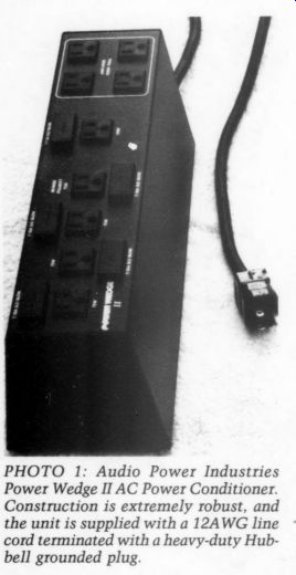
PHOTO 1: Audio Power Industries Power Wedge II AC Power Conditioner. Construction
is extremely robust, and the unit is supplied with a 12AWG line cord terminated
with a heavy-duty Hub bell grounded plug.
Audio Power Industries describes the Power Wedges as ‘multiple technology ’ AC power conditioners and they make a point that their conditioners are based on ‘well-established engineering principles ’ (possibly contrasting them selves to some of the more ‘flaky ’ power conditioning concepts, such as a magic clock which I won't mention by name). API is reluctant to reveal the technical details involved in their design, since patents are still pending. Mr. Edelberg did say their research showed that conventional RFI filters intended for computer applications were not tailored to the needs of audio equipment. The working components of the Power Wedge II are mounted in a robust two piece all-metal case, secured from peeking or tampering with four pop-rivets.
The unit comes with a 122AWG line cord connected to a heavy-duty Hubbell AC plug.
The designers of this conditioner have addressed three critical issues. First, the device offer suppression of spikes and damping of AC power surges and transients.
Second, it provides RFI filtering with out the resonance problems associated with conventional RFI and EMI filters.
The filters have been designed so they won't limit the peak currents demanded by high-power amplifiers.
Third, the five transformers offer isolation between low-level components, minimizing the possibility that noise generated by one component might affect the performance of another. This is particularly important in the case of CD players, which dump a substantial amount of digital garbage back onto the power line. The isolation provided by the Power Wedge II will prevent noise generated by the CD player from adversely affecting the performance of your preamp or power amp. If you use a separate digital-to-analog processor as part of your CD playback system, the power conditioner will isolate digital noise generated by the CD transport from the analog circuitry.
I have a separate power supply for my D/A converter and analog circuitry. My CD player has two line cords, which I have connected to separate isolated out lets on the PW II (Fig. 1).
Each low-level outlet on the device is fused to prevent overload of the individual transformers. The fuse holders are cleverly designed-they also house a spare fuse of the same value. The Power Wedge II also contains a main circuit breaker, primarily to protect the unit from power amps which exceed its 1.2kW continuous capability.
I questioned Mr. Edelberg about the nature of the filtering used in the Power Wedge II, along the lines of ‘how many decibels down is it at specific frequencies? ’ Although he would not offer a specific specification, he said their filtering addresses the entire spectrum above 60Hz. 1 also asked if electrostatic shielding was used between the primary and secondary windings of the transformers.
They don't use conventional electro static shielding, but they claim to pro vide isolation between the windings using a proprietary method.
I hope readers will forgive me for being so vague about the technical de tails-it certainly runs contrary to my normal style, but it's the best I can offer without drilling out the rivets and sketching out a schematic. If the manufacturer ever offers more technical details, I'll certainly pass them on to you.
Meanwhile, I'll respect the manufacturer's right to secrecy.
I have used the PW II in my own sys tem for about six weeks. I also tried it on the system owned by fellow audiophile Lorelei Murdie, who assisted me in evaluating the Adcom ACE-515. We both agree its performance is excellent.
In direct comparisons with the ACE-515 (without changing any MAAD parameters), the Power Wedge II is superior in every respect.
The Power Wedge offers the same kinds of improvements as the ACE-515, but to a much greater degree. The sound is considerably cleaner with the Power Wedge installed, as if another layer of sonic dirt has been removed. This is especially helpful to recordings with a lot of high-frequency energy, such as Dutoit's London CD of Respighi's The Pines of Rome. But, it is the midrange that benefits the most from the sonic cleanup. Lorelei's Vandersteen IICs have less upper midrange grit than with the Adcom. I hear considerably greater inner detail in heavily scored passages.
The system reveals more of the subtle ties imparted to the music by the per formers, especially articulations and dynamic shadings. Solti's London CD of Siegfried's Funeral Music, on disc 4 of his complete Gotterdammerung, is a case in point.
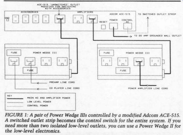
FIGURE 1: A pair of Power Wedge Ills controlled by a modified Adcom ACE-515. A switched outlet strip becomes the control switch for the entire system. If you need more than two isolated low-level outlets, you can use a Power Wedge II for the low-level electronics.
More hall ambience is revealed using the Power Wedge II. On natural-sounding orchestral recordings, the soundstage is larger, especially in depth. Antal Dorati’s Mercury CD of Schoenberg's Five Pieces for Orchestra and Fritz Reiner's RCA CD of the Mussorgsky Ravel Pictures at ar. Exhibition are excellent demonstrations of the improvements in ambience and depth. Dorati's Mercury CD of Respighi's The Birds, a disc that never sounded acceptable before I installed the ACE-515s, is better than ever with the PW II. The tightly scored strings at the beginning now emerge with a combination of sweetness and detail I'd never heard from this disc.
When I reviewed the ACE-515, I commented that adding the power amplifier to the conditioner resulted in only a minor improvement over what it did for the low-level electronics. This was definitely not the case with the Power Wedge II. Supplying the power amp with filtered AC from the PW II resulted in a sonic improvement nearly as great as that provided by the low-level conditioning. This may be due partly to the isolation provided between the low-level electronics and the power amplifier, which the ACE-515 doesn't offer. The low end of both systems gained in impact and extension when the power amp was connected to the Power Wedge. The ACE-515 made little difference in the bass performance of our power amplifiers. Overall, the day-to-day consistency of my system has been considerably improved. I'm still not prepared to say that all variability has been eliminated, but my system is much more consistent than it was with the ACE-515s.
Given the choice between the Power Wedge II and Adcom ACE-515, I easily opt for the former. Although it is considerably more expensive ($439 versus $180), Audio Power Industries offers a less expensive alternative if you don't need five isolated low-level outlets.
Their Power Wedge ITI has only two 75W isolated outlets and two high-current (1.2kW total) power amp outlets. The only difference between the Il and PW III is in the number of outlets provided. The PW III is priced at $239, only $60 more than the ACE-515. If you have a ‘nor mal ’ CD player with only one line cord, the two low-level outlets will be enough to power your preamp and CD player from isolated outlets. The PW III's price tag is low enough that you could conceivably buy a second one for your power amp, allowing you to operate your power amplifier on a separate AC circuit.
Switching the Power Wedges
Does this mean the ACE-515 has been rendered obsolete? Not really. One of the most attractive features of the Adcom conditioner is the turn-on and turn-off sequencing it provides for components, as I described in 2/91. Since I've found this feature useful and desirable, I was reluctant to part with it. The first time Lorelei and I listened to the Power Wedge II, we did careful listening comparisons to determine if the ACE-515 could be used with the PW II without degrading the performance of the latter. I was pre pared to remove the filter components in my own ACE-515s and use them simply for system switching if they proved detrimental to the performance of the Power Wedge.
Our listening procedure was simple-play a selection with the device plugged directly into the wall outlet, then play the same passage with the Power Wedge plugged into one of the grounded outlets on the ACE-515. We tried this on several recordings and, to our pleasant surprise, found that the sound improved even further with the two conditioners used together. Throughout my six weeks of experimentation with the PW II, I haven't found any negative effects on its performance when it is used with the ACE-515.
To retain the switching benefits of the ACE-515, you'll need to plug a pair of Power Wedge filters into the Adcom conditioner. This is where the more economical PW III might be a good choice, provided two isolated low-level outlets are sufficient. You'll also need to modify your ACE-515, since it doesn't have a grounded, switched low-level outlet.
This is simple enough to correct. The Adcom conditioner has an unswitched, grounded outlet, which can be reconnected so it is switched with the rest of the accessories outlets.
If you remove the cover from your ACE-515, you will notice that the black, hot wire is connected to the unswitched outlet with push-on connector. The other end is soldered to the PC board.
Remove the push-on connector from the outlet and unsolder the wire from the PC board. Discard this wire. It is only 16AWG, too light for this modification.
Now, simply solder a short 12AWG stranded jumper wire from the empty terminal on the switched outlet to the hot terminal on the nearest accessories outlet. You now have a grounded accessories outlet that is switched with the rest of these outlets. My modified ACE 515 is shown in Photo 2. Plug your low level Power Wedge into this outlet, and plug the Power Wedge used for your power amplifier to one of the ACE-515's power amp outlets. If you have a separate power line for your power amplifier, you'll need two ACE-515s, as I described in 2/91. You need to modify only the ACE-515 used for your low level electronics.
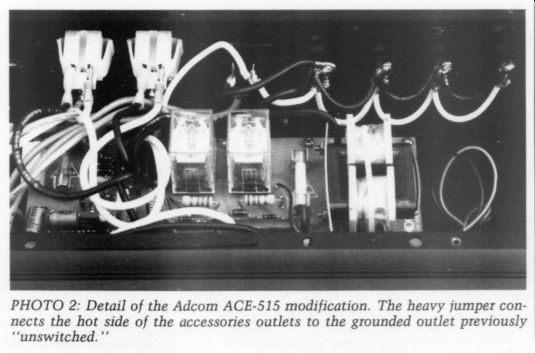
PHOTO 2: Detail of the Adcom ACE-515 modification. The heavy jumper connects
the hot side of the accessories outlets to the grounded outlet previously
‘unswitched.’
The PW II is an excellent power-line conditioning system. It is certainly the best affordable conditioner I've used. (I also have experience with the Tripp-Lite LCR-2400; I use one at work on my recording equipment.) If you still don't use any power-line conditioning, I highly recommend this product. If you already own an Adcom conditioner, you can significantly improve the performance of your system by adding a pair of Power Wedges as I described above, while retaining the turn-on and turn-off sequencing of the ACE-515. But, if you plan to purchase only one conditioner, the Power Wedge II is the one to buy.
Audio Power Industries also manufactures a few other variations on the Power Wedge theme. All these products offer identical performance to the Power Wedge II; the only differences are in the number and power ratings of the various outlets. I've already mentioned the PW IMI, with two 75W isolated low-level out lets and two power amp outlets. The Power Wedge I has six isolated 75W low level outlets and four power amp out lets. The V is a high-current version of the III, intended for high-current power amps. The pair of power amp outlets are rated at 20A total (2.4kW), while the two isolated low-level outlets have a reduced rating of 45W each.
They also make a Power Wedge IV and IVA. Both are intended for video installations. The PW IV has two 45W isolated outlets for video recorders and laser disc players, one 150W isolated outlet for video processors, and one 200W isolated outlet for video monitors. Four power amp outlets, 1.2kW total, are included.
The IVA has the same power amp out lets, but with three isolated low-level outlets-two at 75W each and one at 300W. Whatever your particular setup may be, you can probably find a Power Wedge or combination of them to suit your installation. For my particular bi amped setup, a Power Wedge IV on the low-level electronics, combined with a pair of PW IIIs for each power amp, would seem to be the ultimate solution.
This will allow the use of three separate power lines.
Power Wedge II AC Power Conditioner. Audio Power Industries, 2624 S. Rouselle St., Santa Ana, CA 92707, (714) 545-9495. Price: $439.
READER'S QUESTIONS BACK IN THE MAY 1991 ISSUE of Stereophile magazine, I reviewed the Grado HP-1 headphones. In that review I gave a conceptual description of the headphone amplifier I built and use as reference.
Since that review was published, I have had several requests for information on my headphone amplifier. Paul Mouritsen is both a TAA and Stereophile reader.
He has been using a headphone amplifier based on a Signetics NE5535 dual opamp, with 3.92k pull-down resistors.
His amplifier uses the power supply I described in TAA 4/90. Paul owns Beyer 990-PRO 600 ohm headphones and wants a better, dedicated amplifier to power them, so he has asked if I will share my amplifier design with TAA readers.
The schematic of my headphone amplifier is shown in Fig. 2. My perfboard prototype is shown in Photo 3. Only the left channel is shown complete in Fig. 2; the right channel is identical. This is an adaptation of the preamp line stage shown in Linear Technology's LT1010 buffer amp data sheet. IC1 is a Linear Technology LT1122CNS8 op amp, which provides the gain for the circuit. IC1 is buffered by IC2, the LT1010CT. I discussed both of these devices in detail in 'Ask TAA' issue 2/90. The LT1010 is biased for heavy Class A operation with the 33Q bias resistor. A heatsink is essential. I use one of Digi-Key's 5W clip-on coolers (#HS-111). The heatsinks should be fastened to the LT1010CTs using white thermal compound and 4/40 hardware.
The 2N5457 N-channel JFET and the adjustment resistor (Rp; form a 2mA current source, which biases the output stage of the op amp for Class A operation. In 'Ask TAA ’ 1/91 1 described the trim procedure for this resistor in detail, so please refer to that issue for further information. The 2N5457s are available from Digi-Key by calling (800) 344-4539.
Siliconix manufactures a J555 2mA current source, which has only two leads and requires no external trimming. This appears to be a much easier way to bias the op amp. However, the J555 data sheet specifies the tolerance as =0.6mA, which is 30%. I consider this too loose.
I prefer them matched to within 5%.
All resistors are 1%, 1/4W metal film, preferably Roederstein. Old Colony's 0.5 W resistors are fine. The 10k and 1k resistors set the circuit for a voltage gain of 11. I've set the bias return resistor at 10M-ohm, instead of the usual 1M. This reduces a subtle loading effect on the volume control wiper. If you can't locate a 10M resistor, you can substitute a 1M with only a minor degradation of performance. Perhaps with enough demand, Old Colony will carry a 10M-ohm metal film resistor. The pair of capacitors labeled C_opt are optional compensation capacitors. I don't use them since I find the sound is cleaner and more detailed with the circuit operating wideband. haven't experienced any oscillation problems with this circuit when it is used without the capacitors. If you wish to be more conservative with the design, use the best quality 22pF polystyrene capacitors you can find.
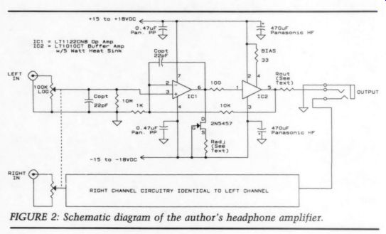
FIG. 2
The volume control I used originally was a blue Alps 100k log taper pot, sold by Old Colony as #VR-100KB. I chose 100k, rather than 50k, to keep the input impedance as high as possible. The 100k input impedance allows the amplifier to be driven by vacuum tube circuits with out difficulty. You may have noticed that the pot shown in Photo 3 isn't the blue Alps control. I'm now using the large black, premium grade Alps pot in my amplifier, but I don't know of a single American source for this pot. The black Alps pot does offer better performance than the blue one, but unless you're making a trip to Japan, you'll probably have to use the VR-100KB. The blue pot is still extremely good and is used by several high-end preamp manufacturers.
The output resistor (Roy) is optional; if you use it, its value will depend on the impedance of your headset. The LT1010 buffer amp will drive headsets with impedances of 40 ohm or higher without the [...]
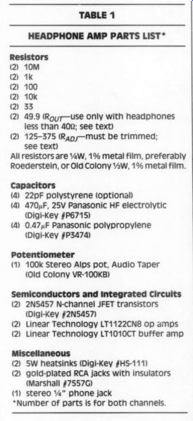
TABLE 1---HEADPHONE AMP PARTS LIST
Resistors (2) 10M 2 1K (2) 100 (2 10k @ 33 (2) 49.9 (Royr-use only with headphones less than 409; see text) (2) 125-375 (Rap -Mmust be trimmed; see text) All resistors are ½ W, 1% metal film, preferably Roederstein, or Old Colony 2W, 1% metal film.
Capacitors (4) 22pF polystyrene (optional) (4) 470pF, 25V Panasonic HF electrolytic (Digi-Key #P6715) (4) 0.47uF Panasonic polypropylene (Digi-Key #P3474) Potentiometer (1) 100k Stereo Alps pot, Audio Taper (Old Colony VR-100KB)
Semiconductors and Integrated Circuits
(2) 2N5457 N-channel JFET transistors (Digi-Key #2N5457) (2) Linear Technology LT1122CN8 op amps (2) Linear Technology LT1010CT buffer amp
Miscellaneous (2) 5W heatsinks (Digi-Key #HS-111) (2) gold-plated RCA jacks with insulators (Marshall #75570)
(1) stereo 1/4" phone jack
*Number of parts is for both channels.
-----------------
A preamp manufacturer generally has no control over the type of headset used by the owner, so they try to make their headphone amps as ‘universal ’ as possible. The problem with a universal head phone amp is that performance is com promised for all types of headphones.
The series output resistor prevents the amplifier from delivering a constant voltage to the headset at all frequencies.
This is due to the fact that no headphone has a flat impedance curve. As a result, the output resistor actually changes the frequency response of the headphone.
My amplifier is not an 'all purpose' design. It has been designed for dynamic headsets with impedances of 4 0-ohm or higher. It will not drive electrostatics and won't work with low-impedance headphones unless you install a series resistor. The value of the resistor should be 40-50 ohm if you are using 8 ohm headphones. I consider this a serious performance compromise. If you must drive 8 ohm phones, you really need a small power amplifier. Mr. Mouritsen mentioned the Lang Class A amplifier in his letter (Old Colony kit KV-2S). This would be an excellent choice for low impedance headphones.
The power supply is critical to the performance of this circuit. In my prototype, which I use for all my live con cert recordings at The Crane School of Music, I mounted the regulator circuit in the middle of the perfboard, with the left- and right-channel circuits on either side. My regulator is the same circuit as the Old Colony KG-5 kit, which I described in issue 4/90. I perf-boarded the prototype before the Old Colony PC board was available. I mounted the power transformer and rectifiers in an outboard chassis. The KG-5 supply has the rectifier diodes on the PC board. If you use the KG-5 supply, I would mount the toroidal transformer in an outboard chassis and keep the regulator PC boards in the same chassis with the headphone circuitry. This keeps the magnetic field from the transformer away from the circuitry, but allows the regulation to be kept as close to the amplifier as possible.
The transformer can be connected to the regulator with an umbilical cord. I'd use 14AWG stranded wire for this connection. You can make an excellent wire by using multiple strands of the Neglex 2534 center conductors. Remove the outer insulation and shielding from a length of the 2534. Parallel six of the center conductors for each of the four wires you'll need to connect the two transformer secondary windings to the PC board.
Local power supply bypassing consists of a 470uF/25V Panasonic HF series electrolytic in parallel with a Panasonic 0.47uF/50V polypropylene for the positive and negative rails of each channel.
These are Digi-Key part numbers P6715 and P3474, respectively. For even lower ESR, you can substitute 35V HFs, part number P6726. These capacitors should be mounted close together, and as close to IC1 and IC2 as possible. I got carried away when I built my prototype and by passed each active device with its own 470 uF capacitor, so I have a total of four per channel.
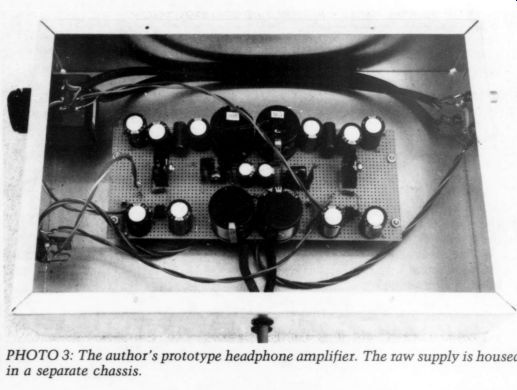
PHOTO 3: The author's prototype headphone amplifier. The raw supply is housed in a separate chassis.
All my internal wiring is done with Joseph Grado Signature Laboratory Standard Audio Cable. This excellent cable is a four-conductor shielded cable similar in construction to Neglex 2534. But, it improves on the 2534's performance in two important respects. First, Grado's shield is also oxygen-free. Second, during the manufacturing, the copper is drawn much slower than 2534. In addition, each center conductor consists of extremely fine copper strands spirally wound on a nylon core. Grado sells this cable for $5/foot. For more information on this cable, contact Joseph Grado Signature Products, 921 Tice Place, Westfield, NJ 07090, (908) 233-5893.
As the photo shows, I've used this shielded cable to connect the input jacks to the volume control. I also used paralleled center strands from this cable for the other signal and ground connections.
The only chassis grounding point is next to the input jacks. The output head phone jack is mounted on the chassis with a nylon insulator to prevent a ground loop. The input RCA jacks are Marshall Electronics 7557G gold-plated connectors which I mentioned in 1/91.
Since no one seems to make a premium quality gold-plated 1/4” phone plug, we're stuck with the usual Switchcraft type nickel-plated connector.
I'd like to clear up some confusion regarding the suppliers of Linear Technology ICs and Mogami Neglex connectors and cable. Both suppliers bear the name Marshall, but they are not the same company. The distributor for Linear Technology parts is Marshall Industries, 9674 Telstar Ave., El Monte, CA 91731, (818) 307-6000. You can get the number for the Marshall Industries branch nearest you by calling Linear Technology at (800) 637-5545. The distributor for Mogami Neglex cables and connectors, including the 7557G RCA jack, is Marshall Electronics, PO Box 2027, Culver City, CA 90230, (213) 390-6608.
Finally, TAA reader Bob Green, an employee of Audio Technica, contacted me regarding the correct number for the positive regulator supplied with the KG-5 kit. Old Colony supplied him with the right parts, but the wrong data sheet.
The positive regulator is the LT1085CT; the negative regulator is the LT1033CT.
Both are 3A, adjustable regulators. Linear Technology also makes fixed versions of the positive regulators, which bear the LT1085-5 and LT1085-12 designations. The data sheet for these devices was sent to him by mistake.
LT's data book is a little confusing. In the case of their 1.5A positive regulator, the LT1086, the adjustable and fixed versions are on the same data sheet. But, the LT1085 series are covered on two separate sheets. If you ordered the KG-5 kit, you undoubtedly have the correct parts, even if the data sheet is wrong.
Old Colony will send you the correct data sheet if you call or write.
-----------
AREN'T YOU A FAMOUS AUTHOR?
Maybe you've never thought of yourself as an author, but that shouldn't stop you from telling your story. If you can write a letter, you can relate your account of how you solved a problem, improved a lackluster machine or speeded up a process.
Maybe you needed a special tool or gadget that nobody makes and you made it yourself. Your ingenuity shouldn't go un rewarded. Write up your project, large or small, and send it along. On really large projects, write a short proposal first to make sure that we aren't about to publish a similar one. We pay $80 per page minimum for articles! So warm up your word processor and share your adventures.
-----------------
Audio Aids
MEGAFARAD POWER SUPPLIES
BECAUSE OF THE tendency of some audiophiles to go overboard on everything they do, they are likely to make a certain error when designing a power sup ply: too much capacitance in the power supply filter. A rational manufacturer is constrained by economics, but nothing prevents an amateur from assuming that with a few more farads, his hum problems will vanish and he will have the perfect power supply. Not so, and for reasons you might not suspect: the power transformer and rectifier will overheat.
Consider the following example. It's exaggerated a bit to make it easy to deal with the numbers, but is not impossible. The capacitor in Fig. 1 will charge to almost the peak value of the rectified sine wave in Fig. 2. (If you drew zero cur rent, it would be at the peak.) It is charged only when the rectified voltage exceeds its stored voltage-in other words, for a short time in each cycle when the sine wave is reaching its peak.
Now assume that to keep the ripple voltage low, you have used sufficient capacitance to make the charging time ‘t ’ equal to Y100 of the time between cycles ...
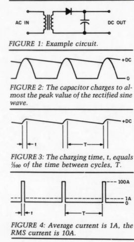
FIGURE 1: Example circuit.
FIGURE 2: The capacitor charges to al most the peak value of the rectified sine wave.
FIGURE 3: The charging time, t, equals Yoo of the time between cycles, T.
FIGURE 4: Average current is 1A, the RMS current is 10A.
... ‘‘T ’’ (Fig. 3). The actual capacitor value depends on the current drain, which is unnecessary for purposes of illustration.
This can be treated mathematically, but it has taken me 25 years to forget whatever it was I learned in college (actually I had forgotten most of it before graduation). The point I'm trying to make is much more dramatic if you simply look at the example (Fig. 4). You must accept the definition of RMS cur rent and agree that the heating value of a current waveform is its RMS value. To get the RMS value, square the waveform, take the mean of the squared values, then take the square root.
If you assume a current drain of 1A from the supply, and whatever capacitance it takes to make t equal to Y100 of T, then you get an input current wave form through the rectifier (Fig. 4).
Take a minute to think about this and satisfy yourself that I'm not using smoke and mirrors. If the output current is 1A and input current is flowing for Y10o of the time, then the peak current is 100A (assume the rectifier will handle this much).
Your average current is 1A. But what do you suppose your RMS current is? Square the waveform, giving the same waveshape with peaks of 10,000, divide by the duty cycle of 100 to get the mean value of 100, then take the square root of 100 to get the RMS: 10A. When the average current is 1A, the RMS current is 10A. No wonder your rectifier and transformer are getting hot and your efficiency has gone down the drain. In general, the ratio of RMS to average cur rent goes up as the square root of the duty cycle.
You can set up a circuit on the bench and test this result, but be warned that most ‘RMS ’ meters measure nothing of the sort. They measure peak or aver age and read out RMS by using whatever conversion factor the maker thought suitable. I ran tests using a modern Phil ips scope that calculates point by point from the displayed waveform, and I also used a thermocouple voltmeter that by definition reacts only to the heating value. They agreed very closely, while a pair of DVMs measuring the same wave form read out garbage.
ALAN S. DOUGLAS, Pocasset, MA 02559
OP AMPS APPLIED
FOR SEVERAL YEARS, I have been applying lessons from TAA to enhance the performance of a Hafler DH-110 preamp and DH-220 amplifier, followed by a Magnavox CDB472 CD player. One of my projects was to replace the phonograph pre amp stage with improved circuitry and eliminate electrolytic capacitors from the signal path. I will discuss the resulting IC opamp phono preamp stage.
Figure 1 shows one channel of the phono preamp. An opamp feedback amplifier forms the RIAA frequency rolloff, with a current buffer inside the feedback loop. These components have resulted from tinkering and evolution, so their final form hinges as much on tests as on textbook principles. A few words about each component will help you appreciate how the tinkering went.
The Op-Amp
I chose the TIL070 due to its high gain, high slew rate, and FET input stage (read very high input impedance). If you have a schematic of the 070, you can see that its topology contains many desirable features, such as cascode stages, current source loading, direct coupling, and so on. References 1 and 2 introduce the important features of this and other attractive op amp circuits. Newer designs are also available; see Old Colony offerings.
The 070 is an uncompensated device, permitting the application of a high-quality capacitor for unity gain stability (C3), instead of one ‘grown ’ on the chip from an oxide. Superior caps are not easy to find, especially those grown from IC chip materials better suited to semiconductor fabrication.
The homemade compensation capacitor began rather oversized and was trimmed by steps to a final measured value of 14pF. Each reduction of value was accompanied by reduced audible slew-induced distortion, which ultimately disappeared before I added the buffer.
Note that no capacitor is between the pickup cartridge and the opamp. In stead, Teflon-insulated coax carries the cartridge signal directly to the op amp input leads. A coupling capacitor was there, but it was eliminated with positive sonic results. This op amp (and many others) puts a vanishingly small DC bias current through the cartridge, so a capacitor is not an absolute necessity.
I modeled the op amp and feedback circuit in a computer, to facilitate optimization of the RIAA and gain-setting resistor and capacitor values. I hand picked them using accurate test instruments during construction. The resistor values may appear somewhat large (and, theoretically, noisy), but this yields small capacitor values. Thermal noise from the metal film resistors is barely audible at maximum volume. The values of R6 and C4 may change, depending on the requirements for loading individual phonograph cartridges. The value of R3 yields a stage gain of 50.
The op amp was operated solo for quite awhile, and it produced a clean but tame sound, better than the circuit it replaced.
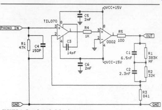
FIGURE 1: One channel of the phono preamp.
However, after reading the discussion about op amps and buffers,? I decided to add a current buffer to spare the op amp from driving any significant load, including the feedback components.
The Current Buffer
This buffer, inside the feedback loop, is a discrete, homemade version of the simple “0002 circuit” presented by Walt Jung. You could more easily use the commercial IC version, but I will reiterate Mr. Jung's concepts.
-----------------------
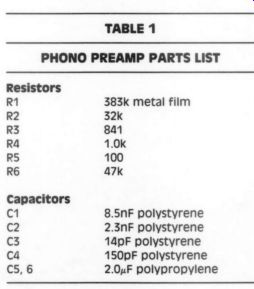
TABLE 1 PHONO PREAMP PARTS LIST
Resistors
R1 383k metal film R2 32k R3 841 RA 1.0K RS 100 R6 a7k
Capacitors
C1 8.5nF polystyrene C2 2.3nF polystyrene C3 14pF polystyrene ca 150pF polystyrene C5,6 2.0uF polypropylene
--------------------
Some people believe that IC devices containing really small junctions could experience thermal effects in audio applications, which may degrade sound quality. Consequently, using discrete transistors and quiet metal-film resistors is believed to provide sonic benefits, by spreading out the heat load into more mass. Furthermore, discrete transistors match much more closely than those ‘grown’ on IC dies. I have not com pared a commercial IC ‘0002 ’ device in this application, however, and its wide application speaks highly of its merits.
The 0002 buffer, as well as other good buffers, has a very high input impedance. This makes the 070 able to attain its output voltage swings with small changes in operating current, causing it to operate predominantly in Class A. As frequencies climb and as the feedback capacitors conduct better, the buffer easily provides the required current. The op amp alone sounded dull, un-dynamic, and closed in when driving the feedback circuit and the remaining preamp circuitry (and tape deck cables) unaided.
Adding the buffer produced a detailed, lifelike, and dimensional quality to phonograph records, at least on par with a beyond-Jung modified Magnavox CD player, equipped with a ‘select’ Philips D/A converter.
The Regulated Power Supply
The DH-110 rails are supplied with about 23V, too much for the circuits presented here. Therefore, I added a textbook? dual IC regulated power supply to provide + 15V to the new circuitry. The only tinkering involved was to add, with sonic benefits, large polypropylene by pass capacitors at the op amp and buffer power supply leads on their respective PC boards. Low ESR electrolytics appear on the regulator boards, of course.
Readers who collect manufacturer catalogs can read that the high-current volt age regulator ICs have the lowest out put impedance and should be chosen for that reason, not rejected for being over kill. Cost differences are slight. Small heatsinks, added to what appeared to be lightly loaded regulator devices, proved worthwhile.
Past issues of TAA contain articles detailing several high-quality regulated power supplies, many of which are desirable in this application and merit serious consideration.
Installation
All conductors used in connecting these boards were Teflon-insulated. Even a couple of inches of wire makes an audible difference in the treble when replacing vinyl-insulated conductors. I applied twisted pairs where feasible to reduce sensitivity to stray fields.
I carefully cleaned all solder rosin from the PC board foil traces. Its presence caused coupling between certain high-impedance circuit branches, with resulting IM distortion.
Conclusion
The upshot of this brief report is to demonstrate that op amps work better when correctly applied. Accounts of IC op amp successes differ, so this material is presented in an effort to help illustrate why.
This project taught the consequences of topological choices and purely practical hardware choices. Expenses have been modest, particularly when compared to the prices of high-end electronics.
From a technical viewpoint, I looked for and exploited the greatest strengths of each major component in this application. The op-amp is wonderful as an instrumentation-sensing device and compensation-summing point. The buffer provides the current muscle absent in the op amp, which is consequently per mitted to operate at idle current and slightly above. The regulator and associated bypass capacitors provide the jolts of current demanded by the circuitry, at very constant voltage. High-quality circuit elements, wiring, and electrical practice are the frosting on the cake.
From a listener's viewpoint, this op amp application has taken a very anemic-sounding stock phono stage from sonic disinterest into the realm of laser like imaging and details, very punchy dynamics and slam, earthquake bass, and effortless highs. In other words, it sounds more like live music.
DARCY E. STAGGS, Orange, CA 92669
REFERENCES
1. Jung, Walt, IC Op Amp Cookbook, Howard W. Sams & Co., Inc. Available from Old Colony Sound Lab (BKS-10, $24.95).
2. Jung, Walt, Audio IC Op Amp Applications, Howard W. Sams & Co., Inc. (out of print).
3. Childress, Hampton and Walt Jung, ‘‘POOGE-4: Philips/Magnavox CD Player Mods, ’’ TAA 1/88, p. 7 and 2/88, p. 19.
4. Paul, Christopher, 'The Buffer, ’ TAA 1/88, p. 23.
Letters
RISE MODIFYING THE KORG A-3
I AM CUSTOMIZING a Korg A-3 digital signal processor. This unit features 16-bit A/D and D/A conversion and is de signed for musical instrument signal processing. I have already POOGEd the A/D-D/A section PP caps and have improved the sound with AD712s. The unit has an older design Sony A/D converter based on an integrating conversion technique. I have built a small card to replace that chip with a Motorola Delta Sigma converter 64x oversampling thereby eliminating the 11th-order anti-biasing filter and the sample and hold section.
For the output section, I will use Dual 20-bit Colinear DACs to replace the one multiplexed 16-bit DAC BBPCM56.
I wish to use Paul Marchese's filter design and CV converter, but I have a problem. The sample rate is 37.1kHz and the output is 4x oversampled which gives me 148.4kHz.
Can you refer me to a source for tables or perhaps an IBM program to determine the values for resistors and capacitors for the GIC FDNR filter adjusted to this
THOMAS FIGUEIREDO, Santa Rosa, CA 95404
Paul Marchese replies:
That's an impressive modification you’re undergoing. Besides omitting high-order, phase-distorting, anti-aliasing filters, sigma-delta converters have other advantages over conventional A/D converters.
Since the sampling rate is 37.1kHz, what is the maximum frequency of interest! It cannot be 20kHz because that value will alias back about half the sampling rate and look like 17.1kHz. The 4x oversampling at the D/A end does not change the fact that the maximum frequency at the input cannot be greater than 37.1k/2 or 18.55kHz, and this is assuming an infinitely steep anti-aliasing filter. If your machine has the same Nyquist-to-cutoff frequency as a CD player (44.1k/2/20k), then the maxi mum frequency is 16.8kHz. Therefore, let's assume it's 16.8kHz.
On the A/D side, a 64x oversampling SD would sample at 2.37mS/S. Although additional filtering occurs on this chip, don't forget a first-order, low-pass filter (at about 25kHz) before the input. A series 2.87 k-ohm resistor with a shunt 2.2nF capacitor should do.
The first frequency component to be of concern at the reconstruction end is:
(4 x 37.1k) - 16.8k = 131.6kHz This equation gives us about three octaves, from the highest frequency of interest in the passband (16.8kHz), to where undesired frequency components of the oversampled data (131.6kHz) are to be attenuated.
Another question is how much attenuation is needed! Since I received so many questions/criticisms on my CD filter (TAA 2/90, p. 8) and because smoothing filters ‘get no respect,' let's go through this step by step. In the time domain, the bottom line of the smoothing filter is to reconstruct the original waveform exactly (or to N bits) for all points in time. The analysis, however, is more computative in the frequency domain.
A 16-bit system has a theoretical quantizing RMS noise floor of -98.1dBV referenced to 1VRMS. A 20-bit system has - 122dBV. One way to look at this noise floor is that this is as good as it gets; it's the system 's distortion/resolution limit. Aliasing on the A/D side or undesired frequency components on the D/A side should be kept lower than this level. A common practice in analog circuits is to be 10dB down in order not to add any significant noise (a - 10dB contributor adds only 5% total noise, whereas a 0dB contributor adds 40%).
These numbers (- 108 and - 132dBV) become extremely small in either case.
Three mechanisms are used for the above attenuation:
1. The smoothing filter.
2. The inherent attenuation of the stepped format at the D/A output.
3. The inherent attenuation of oversampling.
The first mechanism is obvious. The second is a sin x/x band-limiting obtained when changing from an impulse function to a stepped function as in a CD player. The third takes some analysis and will better explain the second.
In the time domain, the original in put signal can be multiplied by an infinite series of impulse functions that have a separation of 1/(sampling frequency). This sampled data is what is on a CD. To change it to a stepped format, the trick is to convolve this signal with a single rectangular pulse of width 1/ (sampling frequency), centered att =0. The result in the time domain is the stepped output D/A with no oversampling, as in example 2. In the frequency domain, this rectangular time domain waveform transforms to a linear phase, sin x/x amplitude response and is a source of attenuation.
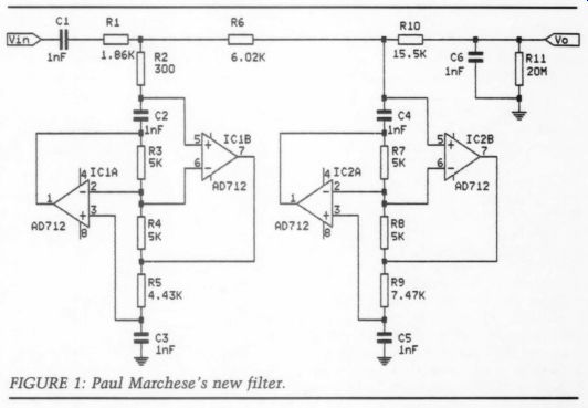
FIGURE 1: Paul Marchese's new filter.
For a 4x oversampled system, the sampled data (as on a CD) must be convolved with four impulse functions, whose separation is four times closer than before. These impulse functions can be looked at as an infinite string of impulse functions multiplied by a step ...
--------------------

TABLE 1--NECESSARY ORDERS
BUTTERWORTH BESSEL 20 bit, -10dB 6 >14 16 bit, -10dB 5 10 16 bit, 0dB 4 7
--------------
... function of pulse width 1 / (original sampling frequency).
Again, the stepped waveform in the time domain trans forms to a sin x/x in the frequency do main and this is before the impulse function is changed to a stepped format.
Don't be alarmed if the above seems confusing, but I don't know a better way to explain the processes 1nvolved. Also, I have not found oversampling at the D/A end described this way and would like to hear from any DSPers out there.
In our case, we will have a 21dB attenuation due to each sin x/x response.
What is the attenuation at the cutoff frequency! A Magnavox player is down 1dB at 20kHz and I believe is corrected in the digital FIR filter. Using the 1dB criterion, a 20-bit system whose undesired frequency components are 10dB below the noise floor would need an additional 90dB attenuation from the smoothing filter. A 16-bit system 10dB below the noise floor would need an additional 66dB, and a 16-bit system at the noise floor would need to be down 56dB.
Table 1 shows the order needed for a given attenuation and filter type.
The Bessel filter has the desirable property of a linear phase response at the expense of a gradual rolloff. The new filter, Fig. 1, has a linear phase response in the passband and no constraints in the transition and stopband. A modified fifth-order Bessel filter can increase the attenuation from 45dB to 60dB at 131kHz. By adding an attenuation peak (a simple resistor in FDNR circuits), this attenuation can reach 83dB. The re bound at 165kHz: (@ x 37.1k) + 16.8k reduces this attenuation to - 79dB, but the two [sin x/x] responses will add 4dB over the 131kHz value. The result is a fifth-order, linear-phase filter that al most meets the stringent 20-bit, - 10dB contributor requirements.
I hope by now the common attitude of putting only an RC on the output of the D/A to smooth the staircase will be revisited. Whether or not you need attenuation of this magnitude is another controversy. One way to look at this is that the frequencies in question are well above the audible range and therefore unimportant. An alternate view is that if you don't attenuate these frequencies, you re not reconstructing the original in put signal exactly (or to N bits).
I do not know of any program or tables for the FDNR filters. They are derived from the passive networks which are widespread. Burton and Treleaven's paper ‘Active Filter Design Using General Impedance Converters ’ (EDN 2/5/73) will probably explain these filters better than I can.
The 12V supplies do not alter the circuit.
TOO MUCH GAIN
I HAVE BUILT TWO of Hans Mortensen's DC300Bs (TAA 1/89, p. 14; 2/89, p. 16) and I'm in the process of assembling two more. The sound is faster and more musical than my Leach power amps.
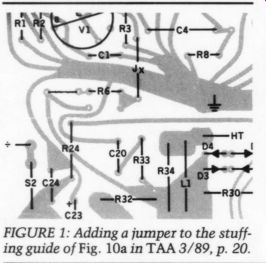
FIGURE 1: Adding a jumper to the stuffing guide of Fig. 10a in TAA 3/89, p. 20.
I built the amps as monoblocks and used a 40VACX2 10A transformer.
My only problem at first was far too much gain, so I checked all the resistor values in the gain stages to see if I had installed an improper value. They all checked out okay. When I changed the R1 tube stage and installed a 100k 10-turn pot, I got the proper gain at the 100 ohm point. I won der if the value of R1 as 100k ohm was a misprint and should have been 100 ohm or perhaps the circuit has a mistake some where else. Or if made a mistake, could you help me by suggesting where to look? If there are any improvements from the TAA article, could you please let me know? I learned basic electronics at night school and have constructed my own preamp, three-way electronic crossover, Leach double-barrel power amp, Leach low TIM power amp, and the DC300B.
I can assemble equipment from circuit diagrams, but I'm not a designer.
ROSS ALLDIS
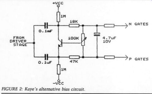
FIGURE 2: Kaye's alternative bias circuit.
Hamilton, Ontario L8P 4N9
Hans Mortensen replies:
Thank you for your letter and your comments on my amplifier. I'm glad you en joy it. The amplification factor of the closed-loop circuit is given by R6/R3 (that is, 12,000/560 = 21.4 times; 26.6dB). So, if the gain is too high, the only place to look for a culprit is the feedback circuit-R6 and R3. I think your problem is that you have followed the stuffing guide almost too meticulously. Proofreading is not always what it ought to be-for which I apologize- but the position of R6 on the stuffing guide leaves the feedback path open-circuited. If you install a jumper as shown in Fig. 1, your problems are solved.
R1 serves two purposes: it determines the input impedance of the amplifier and it keeps the grid of V1 at ground level.
The value (100k) is not critical, but you should be careful not to load the preamplifier too heavily. If it is AC coupled, you'll also cut off some bass.
I'm indebted to Mr. Kaye of Kaye Audio Labs for two suggestions for improvements. I have not tried them yet.
1. Lowering the low -3dB point by increasing C4 to 2uF, and increasing R8 to 2.2 M-OHM.
2. Alternative bias circuit in Fig. 2.
SUPPLIER NEEDED
I AM WORKING on the Dynaco Stereo 400 modification from the article by Bill Rollins in TAA 3/83 (p. 21). Can anyone provide me with information as to a current supplier for the RCA CAO81AE op-amp?
WiLLIAM B. DEMOND, 255 Rice Ave. , Sheridan, WY 82801
EXCITING OP AMPS I'M TESTING A PAR of exciting new op amps in my phono stage. They are the Burr-Brown OPA-627s, compensated for unity gain. They replace the LT-1115s, exceptional devices in their own right.
Yet upon comparison, the 627s produce deeper, tighter bass, cleaner and clearer highs, noticeably better recovery of low level detail, and, surprising enough, dimension.
A pair of NE530s, in a beyond-POOGE 4 CDB 472, were replaced with the OPA-627 (incl. LM334Z current pull downs). Sonic improvements similar to those mentioned above resulted in this exchange. There is absolutely no hint of ‘CD sound ’ from the 472. (The Mercury 432-015-2, Enesco and Liszt Rhapsodies, contains a sumptuous, lavish taste of what CD is capable of.) The unity-gain stable OPA-627 has a slew rate of 55V/uS, while the sister amp, OPA-637 (compensated for a gain of 5 or higher), attains 135V/uS. Both have unity-gain distortion of 0.00003% at 1kHz and are very quiet. Output short-circuit current is + 70/ - 55mA.
I am very excited by these devices and encourage other readers to treat their ears to the delight of the sounds they reproduce. For details, call Burr-Brown at (800) 548-6132.
DARCY STAGGS, Orange, CA 92669
UPGRADING THE FM-3
I READ LES WINTER'S FM-3 letter and Ben Poehland's reply in TAA 2/91 (p. 71). 1 then reread Mr. Poehland's FM-3 article in TAA 4/86 (p. 26). It occurred to me he left a big carbon resistor in the signal path that negates much of what he gained by installing carbon film and metal film resistors. He should bypass it or use an Alps unit to replace it. I am, of course, speaking of the old carbon volume control. I bypassed it on one of my FM-3s and the difference was noticeable, even with all the old parts in place.
I also think that replacing C24-26, 29, and 30 with film type caps would have a beneficial effect on the high frequencies. All are ceramic and are in the audio signal path.
My belief that the FM-3 can sound as good as any tuner on the market, old or new, is so firm I have taken apart one of mine and I'm ordering new parts to POOGE it as much as possible. The parts include metal film resistors, all PS and PP caps after the discriminator transformer, a new PC-8 and PC-12, and a larger box so I will have room for the new regulated power supply and parts.
I realize the expense and work involved will be considerable, but an old FM-3 with all old parts intact gives so many hints of excellence that I believe it will be worthwhile.
HARVEY OTIS LEWIS
Stephens City, VA 22655
PASS A-40 UPGRADE?
I THANK YOU and your staff, along with the contributing editors, for making Audio Amateur possible. I have enjoyed learning more about audio electronics from reading the articles and building a few of the projects.
I have what is probably a simple and commonly asked question about the model A-40 amplifier from Mr. Pass. | wish to lower the bias level of the out put stage a little, from the usual 0.75A per output pair to 0.4A. I had built my most recent A-40 with four pairs of out put transistors per channel so it would operate into 4-ohm loads in Class A, but now I wish to re-bias it for 8-ohm loads again while still using four pairs of transistors.
This is the reason for cutting the bias level in half, but I am not really sure how to do it. Is there an equation used to determine the bias level? I realize that contributing editors like Mr. Pass have business professions that keep them quite busy. I can only ask if you have plans for another article by Mr. Pass in the near future? I found the A-40 article very informative and have put off building a more powerful amplifier in hopes that you might include another Class A amp project by Mr. Pass.
JON S. BECKETT
Hammond, IN 46323
Nelson Pass replies:
I am still getting quite a few letters and calls about the Pass A-40, nearly all of them wanting more performance. I am only able to convince a small percentage that they want a Threshold SA12 (300W Class A, a mere $7,500 per channel), and so I am forced to consider publishing a revised version of the design.
JUST LOOKING
Polydax has announced the DT101,a 1” pure titanium dome tweeter that creates an extended high-end performance. Using a proprietary radius compliance surround technology, the DT101 is characterized by a smooth transient response and precise imaging. Other features include a two-layer voice coil, high-sensitivity level (95dB, 1W/1M), and a heavy duty 10 oz. magnet. The frequency range is 5-30kHz.
For more information, contact Polydax Speaker Corp., 10 Upton Dr., Wilmington, MA 01887, (508) 658-0700.
Analog Devices informs customers of an unusually high early life failure rate on its part number AD847. The failures are restricted to one wafer fabrication lot.
Although most of the suspect product was identified and screened out prior to shipment, a certain amount of the affected material was shipped to customers. This product is traceable as follows:
Shipment date from ADI: June 8 through July 26.
Package types: 8-pin SOIC (AD847JR) and 8-pin plastic DIP (AD847]N) only.
Top brand date codes: 9122 and 9123.
[Units sold by Old Colony are okay.-Ed.] Defective products may be returned for immediate credit or replacement. Con tact your nearest Analog Devices Sales Office for assistance. For further technical information, contact Michael O'Neill, Customer Service Manager, (617) 937-2293, FAX (617) 937-2003.
Sparkomatic has released the Model SR339 electronically tuned AM/FM stereo cassette. Its features include auto scan, up/down seek tuning, 12 FM and six AM programmable memory, and full night-lighting and has flush-mounted controls for one-touch control.
The SR339 sells for less than $100. For complete information on this product, contact the Marketing Department at Sparkomatic Corp., Milford, PA 18337, (800) 233-8831 or (800) 592-8891 in PA.
Rockford has announced three assembly kits developed for industrial /vocational students and hobby kit builders. Kits include a 10W/channel amplifier, two 6.5”, 8-ohm satellite speakers, and a 10", 8-ohm subwoofer. Each comes with a 72-page assembly workbook containing photos, illustrations, glossary, and suggested quizzes.
You can assemble these kits for use with a Walkman cassette tape player or Discman disc player, creating a complete stereo system. You can also decide on the finishing look, colors, and materials, or select finishing materials from Perfect Interface, Rockford ’s accessory division.
De Intermezzo, featuring noted Canadian pianist Robert Silverman playing Brahms' piano Sonata in f, Opus 5 and the Inter mezzo Opus 117 No. 1, is a limited-edition LP available from Stereophile. Recorded with vacuum-tube microphones and tape recorder, the recording provides a fascinating comparison between early and late Brahms. Intermezzo was recorded by the renowned recording engineer Kavi Alexander under the supervision of Stereophile editor John Atkinson.
Best known in his native Canada, where he has performed from coast to coast, Robert Silverman has also appeared with the Chicago Symphony and the Boston Pops, and has performed in New York, Washington, London, Paris, Budapest, Hong Kong, Rio de Janeiro, and the Soviet Union.
The recording is $20.45 available directly from Stereophile, 208 Delgado St., PO Box 5529, Santa Fe, NM 87502.
Mouser Electronics offers a lightweight, compact portable vacuum cleaner for cleaning toner from copying machines and laser printers, as well as for general cleanup tasks.
A 10 micron toner dirt filter (included) protects the motor, and the 1hp/5A mo tor with sealed ball bearings is continuous duty rated. This electronic vacuum is self-contained and static safe. The high impact plastic case stores attachments and power cord.
For more information or a free catalog, contact Mouser Electronics, 2401 Hwy. 287 North, Mansfield, TX 76063, (800) 992-9943, FAX (817) 483-0931.
For more information, contact Rock ford Corp., Educational Services, 613 S. River, Tempe, AZ 85282, (602) 967 3565, ext. 3010.
Optoelectronics offers a 16-page brochure describing the firm's newest hand held and benchtop instruments. Con tents include descriptions, technical data, and useful tips on how to use frequency finding handi-counters, universal counter-timers for lab and field, PC based counters with Windows 3.0 for control and display, active preselector bandpass filters, and antennas and accessories. It is free to all involved in sub-audio to 3GHz.
For more information, contact Bill Owen, Optoelectronics Inc., 5821 NE 14th Ave., Fort Lauderdale, FL 33334, (800) 327-5912 or (305) 771-2050.
Neutrik ’s MPR/FPR series, XLR type panel chassis connectors are the smallest panel mount XLR connectors avail able. Featuring gold-plated contact elements, shell and chassis ground, and self-tapping screws, the connectors snap into printed circuit boards (1.6mm thickness) for pre-fastening with a bottom retention pin. Neutrik's MRP/FPR connectors are available in two female and one male configurations with or without retention spring.
Contact your nearest Neutrik representative or Neutrik USA, 195-3 Lehigh Ave., Lakewood, NJ 08701-4527, (908) 901-9488, FAX (908) 901-9608.
Electronic Design Specialists has announced the EDS-59C series II Semi-analyzer and the Micro-analyzer model 76.
The EDS-59C allows technicians to trace audio, video, digital, or FG signals to the problem area while monitoring DC voltages on its 3.5 digit voltmeter.
The unit displays the device's type, polarity, and condition and beeps differ ent tones for speedy troubleshooting.
The semi-analyzer also checks zener di odes for proper voltages, as well as ne ons, LEDs, and capacitors for leakage, noise and voltage breakdown up to 175V a FPLOT has introduced their FPLOT pen plotter emulator for CAD or other vector graphics programs. Even if your pro gram supports your printer, you can use this device to get higher resolution and faster output. To see your plot before printing, use FPLOT's screen preview feature; it has full zoom and pan capability, and is faster than using your CAD program.
FPLOT gives you full control over your printer. You can choose line thick nesses and plot in all the colors available to your printer. You can even plot large plots on wide carriage printers or break them up into a series of mosaic plots.
FPLOT uses the full resolution of your printer to produce smooth lines.
The stand-alone mod requires DOS 2.0 or higher, with at least 128K of free memory. The background and device driver modes require an IBM PC, XT, AT, PS/2, or compatible. The screen pre view feature requires a VGA, EGA, CGA, or Hercules adapter. Expanded memory ( EMS 3.2 and higher) and a Microsoft compatible mouse are optional.
FPLOT sells for $119. For more information, contact FPLOT Corp., 24-16 Steinway St., Suite 605, Astoria, NY 11103, (718) 545-3505.
DC using its built-in hi-pot tester. An optional infrared detector probe is avail able for repairing remote controls.
The Microanalyzer 76 will test in circuit, using high-voltage signals, components in microwave ovens such as high-voltage diodes and capacitors, magnetrons, and power transformers, as well as TRIACs, transistors, and MOSFETs.
The device also includes a 3 1/2 digit voltmeter that measures up to 5kV AC or DC in two ranges. All special test leads are included, as well as an article on repairing microwave ovens.
For more information, contact Electronic Design Specialists, Inc., 275 Rock Island Rd., North Lauderdale, FL 33068, (305) 720-4497.
Monster Cable Products has introduced Interlink DataLink 100 digital coaxial cable for CD or DAT players and D/A converters that use coaxial cable inputs and outputs. DataLink 100 features a high velocity of propagation for greater clarity and dynamic range. A structured matrix dielectric results in low stored energy and better signal detection. The cable uses a double high density braided shield for better noise reduction and isolation. The cable comes in three lengths: IDL100 0.5m, $29.95; IDL100 1m, $39.95; IDL100 1.5m, $44.95.
Monster Cable has also announced the LightSpeed 100 fiber optic cable. It features a tuned spectral attenuation with optimum signal transfer and low loss for amore accurate, natural sound.
High coupling efficiency and low bending induced attenuation produce high velocity of propagation for lower time smear and enhanced transparency. Its three lengths are ILS100 1m, $39.95; ILS100 2m, $44.95; ISL100 20 ’, $74.95. For more information, contact Gary Reber at (714) 677-4668.
Compact Disc Laser Lens Cleaner
For All CD Players AudioSource has announced the LLC-2 ($29.95), an upgrade to the LLC-1 laser lens cleaner. It is designed to work with any type of CD player, regardless of con figuration. The LLC-2 is a digitally encoded compact disc with two laboratory grade brushes protruding from the inner edge of the disc. The cleaning process takes less than 20 seconds.
For more information, contact Audio Source, 1327 N. Carolan Ave., Burlingame, CA 94010, (415) 348-8114, FAX (415) 348-8083.
The Lazarus Mark II Hybrid differential amplifier uses four 6DJ8 twin triodes (two per channel) as Class A differential cascode voltage amplifiers in a zero feed back design for unrestricted dynamics and clarity. It incorporates a FET-based circuit using special voltage tracking power supplies, which displays the most invisible transition to the output MOS-FETs developed to date.
Controls: AC power, standby/mute switch. Specifications: power output-150W/ channel into 82, 206W/channel into 4-ohm; THD at rated output 0.3%; full power bandwidth-5Hz-80kHz; in put sensitivity (configurable)- normal (1.75V), high gain (0.9V); in put impedance-normal (95k), high gain (47k); polarity-inverting; power requirements-250W (idle) to 1.7kW peak; weight-38 lbs.
Contact Lazarus, 8130 Coldwater Canyon, N. Hollywood, CA 91605, (818) 982-6477, FAX (818) 982-9308.
Recordings
CD RECORDING
Reviewed by Andrea Clark
‘Intermezzo: Works for Piano by Brahms,' Stereophile, PO Box 5529, Santa Fe, NM 87502, (505) 982-2366, FAX (505) 989-8791; LP, $24.95; CD, $15.95.
IN REVIEW OF THE 'Intermezzo: Works for Piano by Brahms’ album, you should expect a critical analysis, as my standards are extremely high. My point of reference, other than a baby grand piano situated in the vicinity of my sound system, is the stunning Ingmar Bergman ATR Mastercut LP, which I consider the most natural solo piano recording I have ever heard.
Attempting to reproduce an instrument like the piano accurately is no easy task regardless or the equipment used.
Few even come close, let alone convince you that you are witnessing a live performance. In ‘Intermezzo,’ I found that despite Stereophile's painstaking efforts and proper choice of recording equipment, the album failed to create that sense of illusion of a live performance.
This is one of the first things I listen for, but rarely find, in supposedly ‘great ’ solo works.
One aspect of the recording that continually reminded me I was, in fact, listening to a recording was the difference in timbre between quiet passages and the louder, busier crescendos. The moment the music became loud, it lost its distinction, presence, and separation. (I do not play classical music very loud, only as loud as it would be heard in a live performance.) I also noticed a ‘ringing ’ type sound accompanying certain very high notes on the keyboard. This seemed to suggest something was unable to capture the natural timbre of that particular high note and instead created a degree of distortion whenever that key was struck.
I also noted several other parts of the recording were somewhat muffled, as though the pianist was either sustaining notes for too long a time with the pedal, or sustaining too many. It simply did not sound clear, or as clear as it should be, and surface noise throughout practically the entire album did not help matters.
Soundstaging during the quiet parts was reasonable, but again, just when I felt relaxed, it became loud and confused with no definition or natural presence.
Had I not been informed in advance, I never would have guessed this was an all vacuum tube recording.
With the exception of the final cut, Intermezzo No. 3,1 did not find the music terribly involving. Having read the literature on the LP jacket and realizing Stereophile's good intentions, I was disappointed. While this album remains one of the better solo piano recordings to which I have listened, it did not give me that ‘illusion ’ so crucial when it comes to separating great recordings from good ones.
As for the CD, I do not mean to sound ungrateful or ignorant, but I believe com pact discs have no place in high-end audio. I fail to see the logic in transfer ring a pure vacuum-tube, all-analog recording to this digital waste. I do not own a CD player nor do I plan to get one.
In my listening experience, I have found them completely artificial, synthetic, and unnatural sounding.
To be fair, however, I did audition the CD on the big Spectral player at a store in Toronto, and, as usual, it did nothing for me. The only difference was the absence of surface noise.
--------------TABLE 1 EVALUATION EQUIPMENT
Well-tempered turntable
Koetsu Rosewood cartridge
MFA Luminescence preamp
Klimo OTL power amps
Tannoy FSM speakers
Cardas HexLink cables throughout
----------------
Response from John Atkinson, Producer of Intermezzo and Editor of Stereophile:
I read the review of Stereophile's Inter mezzo LP with interest, as without feed back from knowledgeable listeners, it is impossible to know whether we had achieved our goals. I was somewhat disappointed, therefore, to see that Ms. Clark was not as impressed with our efforts as we would have hoped.
‘In matters of taste there can be no dispute,' goes the old saying, so I will not take issue with Ms. Clark's dismissal of the Brahms sonata's music as ‘not being terribly involving. ’ I will note, however, that I believed the juxtaposition of this early Brahms piece, with its bombastic, risk-taking, heroic writing for the piano, and the much-later written, gentle, contemplative Op. 117 Intermezzo would provide an interesting contrast, to the benefit of both. I also believe Robert Silverman's performances of both of these pieces met the music's challenge.
When it comes to sound quality, however, Audio Amateur readers will not be surprised to learn I take issue with Ms. Clark's conclusions. First, the record is cut very 'hot' to accommodate the original tape's extreme dynamic range.
Though this means cartridges with limited tracking ability might sound congested during peaks, it would keep the quietest passages out of the medium's noise floor. From Ms. Clark's description of the sound, I suspect her system is incapable of coping with the demands of this recording, either in terms of keeping the stylus firmly in contact with the groove walls-as a fellow Koetsu Rose wood owner, I know that music. Reviewers should always be careful to separate the qualities of the recording they evaluate from those of their playback equipment-something I readily accept is much harder to do than it sounds.
Regarding the tonal quality of the recorded Steinway on Intermezzo, I con cur it does not sound nearly as brilliant as the Bergman film-music disc, which I agree is one of the great piano recordings of all time. But neither was the live piano sound as brilliant, and it was that live sound we wished to capture, not an enhanced version that might be found more acceptable by audiophiles. The microphones we chose to use did give a rather softer, more romantic version of the original in absolute terms-this being the trade-off we accepted to benefit from their neutral midrange and ex tended bass-but Kavi Alexander did a fine job, I believe, in finding a position for the mike array where this was largely compensated for. I have no idea what causes the ‘ringing’ Ms. Clark noted, since no such noise (other than the natural interplay of harmonics present in the piano's original sound) is audible on the master tapes.
It should also be noted, as pointed out in the liner notes, that these tube mikes were more noisy than I would have liked, their background hiss being the dominant noise source on the recording.
I assume this is the ‘surface noise ’ referred to in the review. Nevertheless, if TAA readers do have a faulty disc with excessive surface noise (not mike hiss) or a warp, they should return the LP to Linda Pierce at Record Technologies Inc., 486 Dawson Dr., Camarillo, CA 93012-8090, to obtain a replacement.
Finally, though I am starting to believe my response is becoming disproportionately long compared with the review, I must explain why we issued a CD mastered from an all-tube analog recording. The reason is twofold. I believe it essential to make CDs available as well as LPs; these days many audiophiles do not own LP playback equipment-Audio Research, for example, now sells more line-level-only preamps than ones equipped with a phono stage.
Also, it gave us the opportunity to audition supposed state-of-the-art A/D converters and hard-disk digital editing equipment to see first hand how close these components can approach the goal of absolute transparency. Interestingly, while I believe the Intermezzo CD is about as good as any I have heard in terms of tonal neutrality and freedom from digital artifacts, it is still exceeded in overall naturalness and image palpability by the LP and the original tape.
At least the pricing of our discs reflects the way in which I think the record market is going: the premium LP offering the most natural sound for those prepared to invest in high-quality play back equipment, the less expensive CD offering convenience and even pleasing sound but always some compromise in ultimate quality when compared with the original analog master.
AUDIO ACCESSORIES
Reviewed by Gary Galo, Contributing Editor
JEL Model AX 100 auxiliary selector, $89; JEL Model AX 101 CD-to-phono in put adapter, $29.95. Johnson Electronics Laboratories, Inc., 107 William John Lane, Bonaire, GA 31005.
JOHNSON ELECTRONICS LABORATORIES is unfamiliar to me. The company's AX 100 auxiliary selector expands your preamplifier's input capability by converting one input into five. The AX 100 contains five input connections: AUX 1, AUX 2, AUX 3, TAPE 1, and TAPE 2. Three out puts are also provided. The unit's main output feeds a spare high-level input on your preamplifier, integrated amplifier, or receiver. The two tape outputs feed the line inputs to two different tape recorders. The front panel has two selector switches: MONITOR selects either tape input, or when it is in the source position, it selects the main switch, labeled SOURCE.
The tape-switching capabilities of the AX 100 are not particularly useful, since they allow only the recording of sources routed through this device. Any sources plugged directly into your preamplifier (such as a turntable) cannot be recorded if your tape decks are connected to the AX 100.
The AX 100 is housed in a plastic en closure with aluminum front and rear panels. The inside of the plastic enclosure is coated with a conductive material that provides shielding for the device and the manufacturer claims to use silver-plated switch contacts. The switches are made of plastic and, externally, appear rather flimsy.
The RCA jacks on the rear panel are nickel-plated and the internal wiring is 20-gauge hookup wire. If you need an in expensive way to expand the inputs on your preamp, this device will do the job.
If you're willing to spend more for such a device, I recommend the DB Systems switchbox sold by Old Colony; I've built three and they're a much higher quality device. This device has a more durable silver contact switch and is available with gold-plated connectors. Also, you can use high-quality internal wiring when assembling the device. I recommend Neglex 2515 hookup wire or the center conductors from the Neglex 2534 shielded cable.
The DB Systems kit doesn't provide tape monitor loops but, for reasons al ready mentioned, they're practically worthless on the AX 100 anyway. A word of advice when using any input-expanding switchbox: don't route your highest quality sources through one of these de vices. The additional contacts will de grade the sound on a high-resolution sys tem. Connect your CD player directly to your preamp and let the switchbox handle lower resolution sources, such as an FM tuner, VCR, or other device. Instead, I recommend ordering either Old Colony kit KM-10A (nickel jacks, $45) or KM-10B (gold jack, $55).
CD-to-Phono Input Adapter
The AX 101 contains an inverse RIAA network to allow line-level devices to be played through a magnetic phono input.
It also contains an unequalized phono in put and a selector switch that allows either CD or phono to be played through the phono input. JEL claims an inverse RIAA response of + 1dB with a minimum input impedance of 10k. The unit is supplied in an aluminum, chrome-plated housing with a bottom panel sealed in place with some type of glue. I was able to remove the bottom plate to examine the circuitry. Five percent tolerance car bon film resistors are used along with polystyrene capacitors. The RCA jacks are nickel-plated and the selector switch is a simple DPDT slide type of average quality.
This is not exactly a high-performance audiophile device, and the added noise and distortion that result when you run your CD player through a phono input make this a far from ideal way to listen to CDs. When I play my beyond POOGE-4 CD player through this device, a veil was laid over the sound, with a loss of detail and a narrowing of the stereo image. No audiophile will wish to play a CD in this fashion.
Fortunately, I can't imagine the need for such a device by any TAA reader.
What preamp, integrated amp, or receiver doesn't have at least one high level input? If you're short of high-level inputs, one of the switch boxes mentioned above is a far better solution. But, if for some reason you must have such a device, the AX 101 will do the trick, and on a system needing this product, any sonic degradation is likely to go unnoticed.
If you're thinking of building your own, a word of caution is in order. The inverse RIAA network sold by Old Colony is intended for use with signal generators that can drive a 600 ohm load. It would not function properly with most CD players. The JEL AX 101 is a high impedance device, and thus has no such problem. But you really don't need one of these, do you?
Raymond C. Johnson comments:
In response to the review of our Model AX 100 Auxiliary Selector and Model AX 101 CD-to-Phono input adapter, we offer the following:
The selector switches used in the AX 100 have a 0.1 mill plating and are rated at 10,000 operations.
The AX 101 adapter is intended for the situation where an older amplifier does not have adequate inputs (or perhaps has two phono inputs, as was quite common) and the owner wishes to maintain the integrity of the original selector. It also works well with ‘entertainment systems,' many of which have no auxiliary inputs. Each unit is tested to meet inverse RIAA response to within 1dB and should provide adequate fidelity for these situations.
Book Reviews
SPEAKER TECHNIQUES
Reviewed by David W. Davenport High Performance Loudspeakers, Fourth Edition, by Martin Colloms. Available from Old Colony Sound Lab, PO Box 243, Dept. A91, Peterborough, NH 03458-0243, (603) 924-6371, $34.95.
PERHAPS YOU ARE FAMILIAR with Martin Colloms' work through his many articles in Stereophile or Hi-Fi News & Record Review. Or maybe you are acquainted with his book High Performance Loudspeakers, which has just been released in its fourth edition. It is just what the doctor ordered for the advanced amateur-not a how-to book or a compilation of journal papers, but rather, a solid introduction to the broad spectrum covering loudspeakers.
This book is comprehensive enough to provide a good foundation without having to wade through the details that a professional engineer would require to practice the art. That is not to say it isn't a good starting point to acquire an in-depth knowledge of a particular aspect of speaker building-its references and bibliography are extensive.
Colloms starts the journey with a somewhat superficial general review be fore delving into the real meat of the subject. I would imagine the second chapter was the hardest to write. Whole books have been written on theoretical aspects of diaphragm radiators. How do you boil it down to 24 pages? The section on equivalent circuits nicely ties the significance of different system components to their effect on the audio spectrum.
This type of analysis is important be cause it helps formulate your thoughts when analyzing a system.
The next chapter, 'Transducers, Diaphragms and Technology, ’ provides an overview of different kinds of speakers and insight into the types of trade-offs designers make in the development of a driver, such as the shape of the cone or the structure of the magnet.
The fourth chapter, ‘Low Frequency System Analysis,’ is a reasonable introduction and synopsis, but you should read something like the Loudspeaker De sign Cookbook to realize a design. It does, however, provide good coverage of different types of systems and factors that influence them, as well as effective use of equivalent circuits. This chapter does a nice job of illustrating the interaction of enclosure volume, efficiency, and bass response. Also, fundamental performance limitations are introduced-no 66 The Audio Amateur 4/91 snake oil or attempts at fooling Mother Nature here. It is must reading for anyone who believes he has invented something that rewrites the physics books.
The chapter titled 'Moving Coil Direct Radiator Drivers’ is my favorite; it dissects the driver and discusses each of its constituent parts, covers spectrum from LF through MF to HF, and touches on every aspect with a clear and concise description. For example, did you know that the Neoprene used for surrounds in woofers exhibits hysteresis resulting in stiffness at higher frequencies that renders it inappropriate for use in midrange or tweeter drivers? Not the type of information you are likely to find in a popular magazine.
By far the weakest part of the book is the chapter on systems and crossovers.
The section on digital signal processing is particularly disappointing. Colloms does such a good job elsewhere of explaining complex technical matters that the contrast here is glaring. He focuses on the possibilities of DSP without even attempting an explanation of the under lying principles.
In comparison, the analog material is better-a knowledgeable introduction without in-depth analysis. It provides an introduction to basic crossovers, covers the importance, and effect, of driver impedance on the result, and discusses the amplifier-loudspeaker interface. It's no secret I'm a fan of active crossovers. This chapter provides a good argument for, and introduction to, this subject.
‘The Enclosure ’ is not about alignments-that is covered in the chapter on low-frequency analysis. It does address problems such as mechanical resonances and their solutions. It talks about enclosure materials, cabinet construction techniques, and cabinet shapes. It also contains a short section on that most neglected of all components: the loudspeaker stand.
I am pleased to see Mr. Colloms chose to devote a large chapter to component evaluation-subjective as well as objective. For the objective, he has a short introduction to each test. These tests cover driver parameters like suspension compliance and coil inductance, as well as complete loudspeaker system tests like Doppler distortion and phase response.
The chapter also has a good introduction to computerized testing such as MLSSA and the Audio Precision test set, as well as covering more high-tech stuff like laser measurements.
The discourse on subjective testing is basic material-covering environment, positioning, and acoustics, as well as speaker factors. It provides a consolidated reference for the experienced listener or an introduction to the subject for someone getting acquainted with subjective evaluation.
Although international standards are addressed, only a single page is devoted to this subject, basically a listing. I was left wanting more- perhaps a paragraph explaining each.
Comparison to Earlier Editions
I'm sure many of you already own a previous edition of High Performance Loudspeakers and are wondering what's new in the fourth edition. I'm not one to rate a book by its cover or number of pages, but this edition is about 30 percent larger than the previous one, which in turn was 30 percent larger than the second edition.
Most of these pages are due to expansion of existing topics, although the book contains plenty of new material.
One hot topic these days is bandpass enclosures. A new, large section on this topic is included, as is a section on large film transducers, and another on ribbon speakers. Digital technology makes a debut with a mention of a hybrid digital loudspeaker patent, in addition to ma terial on digital filters. The book mentions the Isobarik enclosure, resistive chamber coupling, line sources, and the moving coil spaced dipole, as well as an expanded discourse on full-range units.
The section on amplifier-loudspeaker interface is expanded, as are those on cut ting down resonances, loudspeaker stands, and testing.
And, of course, we can't forget the new appendix. SB readers will be familiar with the material covered in the appendix on CAD software; it was compiled with help from Old Colony and covers all the programs advertised in these pages.
Conclusions
I have never been one to plug numbers into a canned formula to obtain results I don't understand. I don't even like to rest on an intellectual understanding of a subject; rather, I am comfortable only when I gain an intuitive understanding, that gut feel of what it's all about. Only then can I let my creative juices take over and not be afraid they will lead me to some strange conclusion where the laws of physics are broken. For me, High Performance Loudspeakers fills the bill, pro viding a knowledgeable introduction for the knowledgeable amateur.
All in all, the book was devoid of factual errors, and the few typos that crept in and mis-references to figures were only a minor distraction. High Performance Loudspeakers is a must addition to the library of anyone who considers him- or herself, or strives to be, a serious audio amateur.
A MANUAL ON MICROPHONES
Reviewed by Richard Honeycutt
Microphone Manual, Design and Applications, by David M. Huber, Howard W. Sams & Co., 866 Third Ave., New York, NY 10022, (800) 257-5755, $29.95, 336 pp. softbound (out of print). If you are interested in this book, perhaps your local library carries it. DAVID MILES HUBER is a recording engineer, author, and recording instructor.
All these things show in his book. If what you want is a layman's understanding of microphone operation, without any messy equations, this is the book for you.
And if you also want the kind of insider knowledge about microphone accessories you usually must invest half a career to get, this is really the book for you. If, on top of all that, you want a compendium of sensible expert advice about what mike to use where, and where to put what mike to pick up a certain instrument or ensemble, then put down this magazine right now and head for your local book emporium.
What, still here? Then perhaps you'll want a more thorough look at the Microphone Manual. First, let me share a note about point of view. We design-type engineers and those recording-type engineers look at microphones a bit differently. A book on mikes written from a design standpoint would first introduce you to the basics of voltage and current and resistance and impedance, or let you know in the preface that we assume you already know all these things. Then we'd carefully talk about sound pressure and decibels and sound propagation and wire and electromagnetism and induction and. . .asleep yet? If this sounds interesting to you, per haps Huber's book is not the one for you.
He assumes you know at least enough electronics to understand the rudiments of tuned-circuit and RF detector operation, although he never really admits he assumes that.
The Contents
He begins the book with a basic non-mathematical introduction to the phys ics of sound. By page six he's describing how mikes work, but again with an al most math-free description. Now this isn't meant as a negative criticism; in fact, Huber has done just what he wished to do: he's produced a book chock-full of useful stuff for budding recording engineers, with no more math, physics, and electroacoustics than they must have.
After about 50 pages of introductions to different types of mikes and their characteristics, comes a useful chapter on electrical interfacing of microphones, including the answer to the old ‘H'mmm, now which one's hot-the red wire or the black one?' bugaboo. Then there's a wonderful chapter on mike accessories.
The other 200 or so pages are mike techniques. This includes suggestions on mike selection and placement, stereo mikes and their operation and application, wireless mikes, and mike techniques in video/film production. This is what Huber does best.
If the truth be told, there's a bit of technical sloppiness in much of the physics and electronics. For example, Huber gives the thickness of a ribbon mike's ribbon as 0.08" or 2mm. Now that's more than 4", which would certainly take care of the breath-blast problem, but it also wouldn't give you much output. (Actually, it's about 0.08 mils or 2m.) On another page, he equates an electret mike's diaphragm tension with compliance, when in fact their effects are essentially opposite.
Numerous other examples could be given, but remember these things are not the point of the book. I think what we have is the classic left-brained engineer reviewing a book by a right-brained artist. Look to Huber's book for the artistry of recording-mike techniques and you'll not be disappointed.
A Few Problems
Even the strong part of the book has several shortcomings. First, the coverage of grounding is incomplete. It has a lot of talk about ‘ground loops. ’ This is an unfortunate term because in fact the greatest cause of grounding problems is something called common grounding impedance. And by concentrating on trying to avoid creating those dreaded loops, you're likely to create a common grounding impedance. Check another reference besides Huber on grounding rules.
The book has quite a lot on boundary mikes. This includes discussion of the real frequency-response limitations of a small-plate boundary mike. Would that several sound contractors in my home area douse their blissful ignorance with this section from Huber. But he ignores the other enormous problem of using boundary mikes in a live situation: the stunningly high-fidelity pickup of foot steps and floor creaks. In fact, it contains little coverage of live-performance pick up at all, and nothing on live theater.
This brings us to the final weakness. Huber's last chapter (before he begins the useful appendices) is six pages on sound reinforcement. Maybe in 60 pages he could have done the subject justice. In six, well, he'd better have left it out.
All in All
And so, to summarize: Huber's Microphone Manual is a strong book on techniques of using microphones of all kinds to pick up musical instruments, voices, and ensembles of all kinds for recording purposes. It contains a general introduction that may prove helpful to the novice.
But don't expect precise technical de tails, design information, or non-recording related material. That's neither Huber's purpose nor his strength.
++++++++
Also see: