THE IR REMOTE SLAVE
If YOU, LIKE ME, prefer to have your electronics gear concealed in a cabinet or somewhere else out of sight, you will notice that your remote control will not penetrate 0.5” thick wood, drywall, or other barriers. Existing gad gets that will do this are too conspicuous for my taste. The device I built (Fig. 1), however, will let you use your IR remote to control your audio/video equipment stored inside a cabinet. The only visible evidence of this gadget is a 0.25” hole somewhere in the direction of where you like to point your remote control.
I drilled the 0.25” hole in the wall above my A/V cabinet and attached an IR module with double-sided foam tape on a stud behind the drywall. This necessitated a 5” by 5” hole in the dry wall cut from the back. As this was in my closet, it was not a problem. I saved the plug and taped it back. The 0.25” hole was ‘dressed ’ with an aluminum foil tube (formed on a 0.25” drill), Krazy glued, and carefully inserted in the hole in the drywall. This allows reflections coming from the remote control at a steep angle to reach the IR module. Alter natively, you could substitute a short glass (or plexiglass) rod for the aluminum tube, as an optical wave guide. I tried it and it didn't work better.
The IR module removes the 40kHz carrier from the remote signal and so you must reconstruct it into the signal for the equipment to respond. You can do this with a 555 timer turned on and off in this case with a power MOSFET. You could use a bipolar device, but I have not tried it.
How It Works
The first transistor Q1 inverts the normally high output from the module to low and the LED-driver that follows Q2 helps monitor the circuit's function. I found both LEDs helpful, though my vision does not respond to infrared light.
---------------------
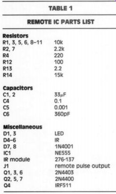
TABLE 1 REMOTE IC PARTS LIST
-----------
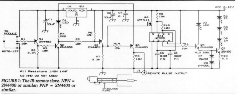
FIGURE 1: The IR-remote slave. NPN =2N4400 or similar; PNP = 2N4403 or similar.
All the transistors came from assortment packs and were selected only for their polarity. I used a surplus 9V wall outlet type power supply and it actually produced +11.5V DC. The IR module can withstand 6.3V maximum and you should use a +5V regulator or a 5.1V zener with a series-dropping resistor and, if you like, regulate the entire circuit with an LM317-type regulator.
The MOSFET driver Q3 needs a bit more than 5V to turn on the MOSFET, so it is powered by the higher voltage.
The Q6 stage provides an output for my Philips FC-60 cassette deck remote control input. I have not yet checked the function of this. Leave Q6/R14/R8 out if you don't need it.
The MOSFET turns on pin 1, powers the 555 timer that is set to oscillate at 40kHz. The 1,000pF and 360pF capacitors were selected with a frequency counter on the 555 output, and the duty cycle is set to 50/50 with R9 and 10 to conform with the remotes for my equipment. This may work with a different duty cycle, but I haven't tried that since the circuit works fine.
The device also has a buffer, Q5, probably superfluous, and an IR-LED driver, Q6. You could probably use less or more than three IR-diodes, but I had them handy so I included them. Be careful with the MOSFET because static electricity can zap it.
I first built and tested the circuit on a breadboard and later moved it to a perf board/case kit (#270-291) with holes made to accommodate LEDs and wires.
The IR module was connected with a microphone cable with the shield connected to the case of the module and to ground. I put the case on top of my equipment, thus aiming the IR toward the white painted inside of the cabinet doors. When these are opened, the IR is dissipated with seemingly no ill effects.
Conclusions
The circuit works very well, but had a small blinking quirk when I connected the remote-out lead into the tape deck and then connected the antenna wire to my TV (thus involving the ground from the TV to the VCR, to the receiver, to the tape deck). I discovered that connecting the antenna shield on the TV to power supply ground via 0.05uF/ 200V film capacitor quenched the flutter on the remote slave to 99.99%. Now it blinks briefly approximately once every five seconds. If you don't need the remote output, I doubt this will be an issue. An LM317-type regulator may also solve this quirk.
--------
ABOUT THE AUTHOR: Christian Svanberg is 37 years old and lives in Florida with his wife and two children. He has worked on electronic projects since age 11. His latest project was a complete overhaul of a pair of Altec 180W triode power amps, to include regulation on all stages including the 1kV plate supply and 8A filament supply. He thinks the sound from directly heated triodes is superior and a great idea for heating cold rooms.
-------
The IR-module is very sensitive and the circuit will optically self-oscillate; input and output need to be physically separated to prevent this. On the bread board I used a black cloth to stop the output.
I'm sure this circuit can be simplified and that someone will find an ingenious way to hide the IR module inside a picture, door handle, cabinet door, base board, or something else. You may also wish to try to add a second or third IR module in your alternate listening location and run a few hundred feet of speaker wire to your B or C speakers and enjoy the control of your music system throughout your house. The possibilities end only with your bank account or patience.
++++++++
Also see: