BUILD A VIDEO TEST GENERATOR
Have YOU EVER NEEDED to repair or calibrate a computer video monitor? Perhaps you didn't like using your computer to generate a test signal? Ever want to know whether it was the monitor or computer that wasn't working? I have. The circuit I present here will generate a test signal for the video in put to a monitor. The circuit generates signals for both IBM-type and standard monitors. If used with an RF modulator, this circuit can even generate a test pattern for a television.
How a Monitor Works
A monitor ‘paints’ a screen of data this way: First, a beam of electrons is aimed across the screen, from left to right.
Wherever a spot of light is to appear, the electrons are allowed to strike the face of the CRT, which contains phosphors that glow when excited by the electrons. After one line is completed, the beam is aimed at the next line down and swept again. Scanning one horizontal line takes 63uS. This process repeats until all of the lines have been displayed, then the beam is returned to the top of the screen, and the process repeats. A standard monitor takes 1/60th second to paint the entire screen.
While the beam is sweeping across the screen, your computer is sending video information that tells the monitor which spots to illuminate. One obvious problem comes to mind: how does the computer know where on the screen the beam is sweeping, so it can send the correct portion of video data? The answer is that the computer tells the monitor when to begin each line, and when to begin a new screen. The signal that tells the monitor to begin a new screen is called vertical sync and the signal that tells the monitor to begin a new line is called horizontal sync. In addition to these signals, the computer must force the screen to be dark at the edges, just before and after the sync pulses. The signal that does this is called blanking.
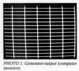
PHOTO 1: Generator output (computer monitor).
Monitors come in two basic types. The ‘standard ’ monitor uses a horizontal frequency of 15.75kHz and a vertical frequency of 60Hz. The IBM-type uses a horizontal frequency of 18kHz, and a vertical frequency of 50Hz. Some monitors will work either way.
Both types can use either composite video input or transistor-transistor logic (TTL) video input. Composite video is sent over a coaxial cable and includes the sync, blanking, and video information as various voltage levels on the cable. TTL monitors use a 9-pin D connector to transfer the video information. On these monitors, the horizontal sync, vertical sync, and video (with blanking) are on separate pins.
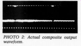
PHOTO 2: Actual composite output waveform.
My video test generator generates the horizontal sync, vertical sync, blanking, and video outputs to produce a pat tern on the screen of a monitor. The pattern displayed is a crosshatch of vertical and horizontal lines. I use a switch to select which horizontal and vertical frequency pair will be generated. Photo 1 shows the generator output displayed on a computer monitor.
The Generator
The generator uses a 2MHz oscillator as a reference frequency (Fig. 1). If switch S1 is set for 15kHz/60Hz, then ICs U1 and U2 divide the 2MHz signal by 128, to produce a horizontal frequency of 15.625kHz. Counters U1 and U2 are down counters. They are loaded with a value of 128 (80 hex) and count down to zero. When zero is reached, the counters are reloaded with 128 and the count repeats. When the counters reach a count of 30 (1E hex), U9, pin 8 and U11, pin 5 generate a blanking signal to blank the screen in preparation for the horizontal sync pulse.
When the count reaches 15 (OF hex), a horizontal sync pulse is generated. This pulse remains active until the count reaches 07, which allows a horizontal sync pulse of eight counts, or 4S. The screen remains blanked until the counters start over. Every 16 counts, U1, pin 13 generates a video pulse that is 0.25uS wide. Since these pulses occur at the same position on each line, the result is a series of vertical bars across the screen.
Counters U3, U4, and U5 provide the vertical timing. Each time a horizontal blanking pulse occurs, these counters are incremented. For the 15/ 60 switch setting, the counters divide by 260, providing a vertical frequency of 60Hz. Like the horizontal timing, the vertical counters count down. When the count reaches 006, U11, pin 9 produces a vertical blanking signal. When the count reaches 3, U10, pin 12 produces a vertical sync signal. The sync signal lasts about 120uS. Every 16 scan lines, U3, pin 13 goes low, which produces a horizontal bar on the screen.
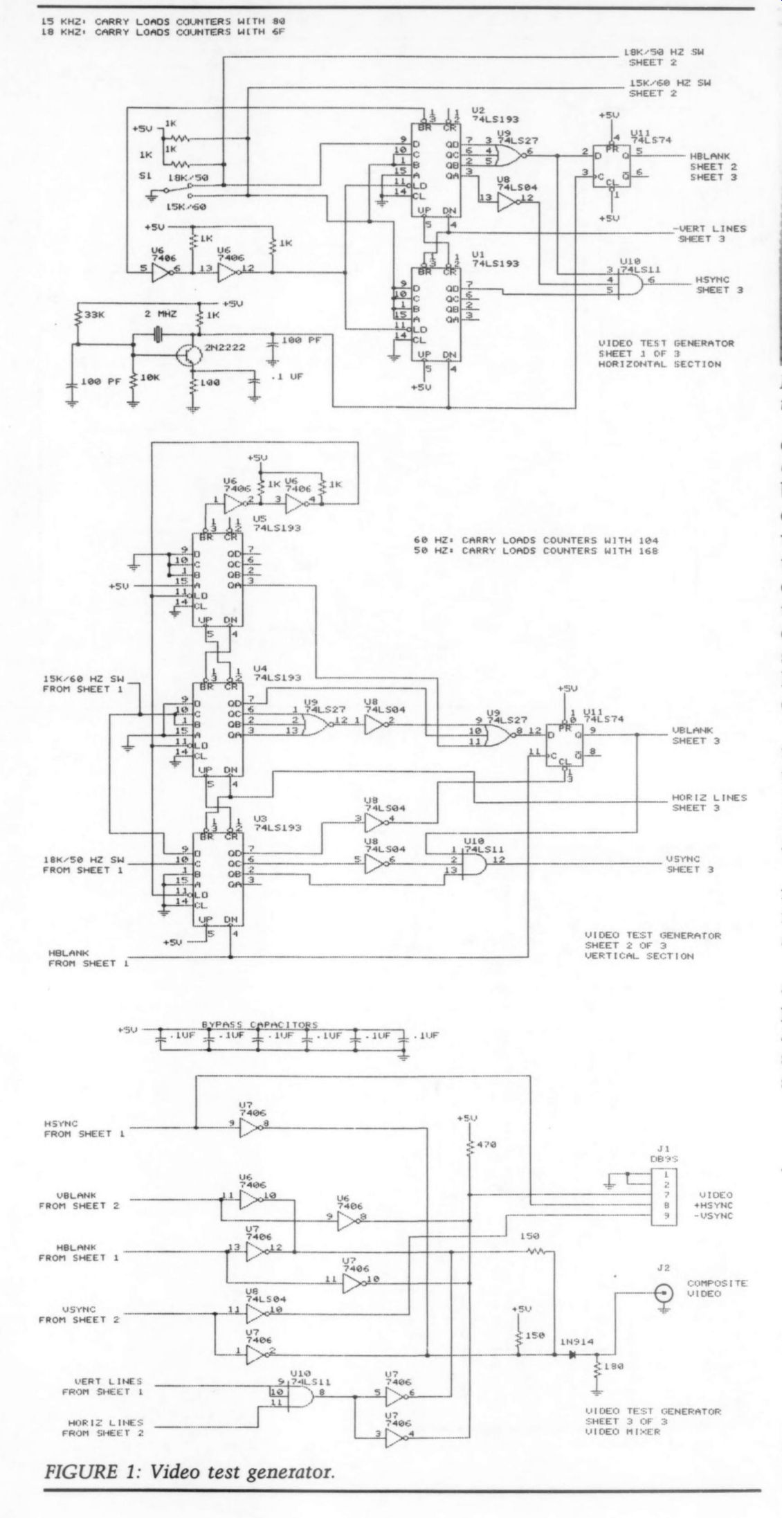
FIGURE 1: Video test generator.
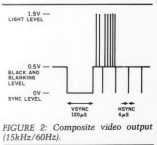
FIGURE 2: Composite video output (15kHz/60Hz).
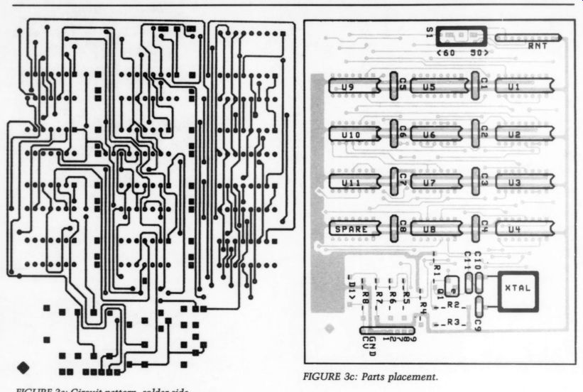
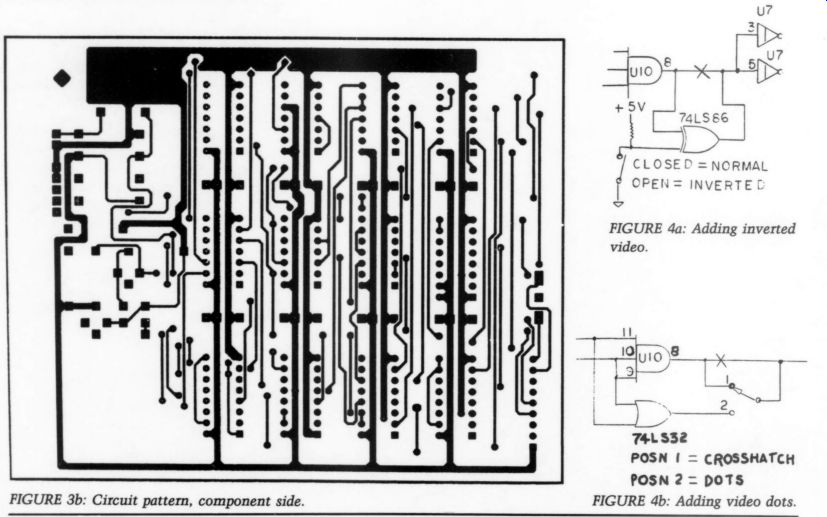
Fig 3a- 4b
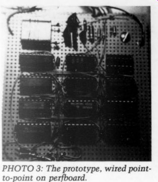
PHOTO 3: The prototype, wired point to-point on perfboard.
If switch S1 is set for 18kHz/50Hz, the operation is the same, except for the divide values. U1 and U2 divide by U1 for a horizontal frequency of 18kHz, and U3, U4, and U5 divide by 360 for a vertical frequency of 50Hz.
The horizontal and vertical bars are mixed by U10, pin 8, which goes low if either a horizontal or vertical bar is active.
The generator produces both TTL and composite video outputs. The composite output levels are shown in Fig. 2. To use the generator with a television, the composite video output should be connected to the input of an RF modulator. Photo 2 shows the actual composite output waveform.
The test generator requires + 5V at about 300mA.
Building the Generator
I built the prototype on a 4” by 3.75” section of perfboard, wired point-to-point. The assembly took about 3 hours. Photo 3 shows the placement of the ICs on the board. As an alternative, Fig. 3 shows a circuit board pattern and parts placement.
If you do not wish to build the 2MHz oscillator shown in the schematic, you can substitute a prepackaged dual in-line package (DIP) type oscillator. Switch S1 is mounted on the solder side of the board. The board is held against the front panel by S1 and a single standoff.
The bypass capacitors shown on the schematic should be distributed over the board, about one for every two ICs (Photo 3).
The generator may be easily modified to produce inverse video or a screen of dots (instead of a crosshatch). Figure 4 shows these modifications. A 74LS86 is used to produce inverted video by inverting the output of Ul0 pin 8. A 74LS32 is used to produce a pattern of dots by allowing the video to be active only where the vertical and horizontal bars intersect.
++++++++
Also see: