A CENTRALIZED POWER CONDITIONER
About FIVE YEARS ago when we were finishing up our multi-amped speaker project, our “final” job was to build an automatic power switching unit with power filtration. This unit worked very well, but it was one of those projects I wish I'd done a little differently. Then about two years ago, we decided to have a 200A service panel put in. I had found a bargain on some constant-voltage transformers, so here was my chance to do it better. I have added some refinements and drawn up the as built schematic in Fig. 1.
Power Problem
The power company is obliged by arrangement with its area authorities to provide electricity which has a quality meeting minimal industry standards.
Its line frequency may not vary and its nominal voltage must be maintained within specific tolerances. While some problems arise from technical non-compliance, which should be corrected when found, most of the garbage that gets into our electrical systems is be yond the company's control.
Noise in the electricity is of many different kinds arising from various phenomena. Most of the time it is random, unpredictable, and sometimes of complex origin which defies certain explanation. I have relied on various references for my information, which are listed at the end of the article. Here I will recap the main points as a prelude to the description of the equipment we built to address these problems.
Service Side Effects
The company's hardware can some times be at fault in the generation of electromagnetic interference which occurs in the incoming service. Poor conduction, intermittent arcing, and leak age can result from insulation-insulator failure and supply transformer and connector defects.
In times of high demand, it is not al ways realistic to expect a stiff 115-120V.
Under-voltages and even sustained over voltages can and do happen.
Totally outside the control of the power company is lightning. The company does have some technical means of protecting the distribution from lightning, but only so much is possible.
Similarly, various other electrostatic and electromagnetic sources, man-made in one way or another (a notable exception being solar activity which can have powerful effects), may get picked up by the transmission line. These are per haps the trickiest problems to locate, and their causes can be really unusual.
They can range from any sort of spark gap device (including metal objects banging together in a field surrounding a line) to electric motors to radio emissions such as CB or amateur. (Amateur operators are very conscientious about their “cleanliness” and are bound by honor (and the FCC) to do right by their neighbors.)
Load Side Effects
The most common disturbances hap pen on your side of the service. They are usually more predictable and easier to trace to their sources than the problems mentioned so far. Loads turning on and off, and sometimes loads running, generate noise which finds its way everywhere in the house circuitry via the service panel. When you consider that good filtering effects can be had simply by coiling a feed wire around a ferrite bar and bypassing it with a small capacitor, it is reasonable to expect that normal stray capacitances and inductance and resistance in the branch circuits can have a real, if difficult to analyze, impact on the way internally generated noise gets around in the sys em. How well the system is grounded should always be considered.
Transient pops are most familiar to us with respect to thermostatically con trolled resistance heaters, burner ig niters, and fluorescent lighting. Some times the transient event is worse than at others; sometimes it didn't seem to happen. This is related to where on the AC waveform the actual make or break took place, i.e., the 'switching angle.” Risk Management This has to do with probabilities and statistical analysis. The objective is to eliminate entirely the simply annoying and mitigate the potentially damaging.
The rules I assumed in putting this sys tem together are:
1. Non-transient electromagnetic interference of all kinds arise from either the service or load side. Corrective measures should be used to attenuate it with only two deliberate stages of general purpose filtration dedicated to the circuit path of interest.
2. Transient noise events of highest amplitude are principally generated on the service side (most notably lightning), while the commonest events are generated on the load side. Repetitive events usually occur on the load side, but can and will eventually occur as a severe amplitude event on the service side. Corrective measures should implement multi stage suppression, with primary protection against large repetitive transients from any source.
3. Sustained nominal line voltage variations occur regularly due to load fluctuations on either side. Corrective measures should include a means of regulating the supply of interest with sufficient current-handling for the anticipated load and must deliver a sinusoidal waveform.
4. Equipment design and ratings must anticipate all eventualities within specified economic and practical parameters. Event incidence and severity probabilities and sophistication level of corrective measures are all variable.
Risk-management criteria are largely a matter of trade-off relationships be tween the potential damage of randomly occurring events (physical damage from transients or overall effect to high-fidelity performance), their probabilities of occurrence, and the costs and feasibility constraints of dealing with them. In planning corrective measures, assume the worst-case scenario that can be practically managed.
Measures Taken The design shown in the schematic (Fig. 1) was undertaken to provide these corrective measures. I plumbed the depths of my far-ranging “junkbox”' and came up with a steel electrical box of just the right size and shape and having knock-outs of just the right sizes and locations. It was originally made for a security system. Alternatives include custom-building from an aluminum chassis or buying a service panel box from your local hardware outlet.
Filter Chain
The input to the conditioning system is a single 120V AC circuit from a breaker on the service panel which is dedicated to the system. This arrangement allows filtering disturbances from all sources outside of the equipment being supported, both incoming service and other loads on the house side. We branch the various outputs to specially identified outlets where sensitive loads are to be supplied. Electronic telephone equipment and the computer station are supported along with the sound system. This is one advantage of centralizing the conditioner.
The EMI/RFI filters are large 30A general purpose line-to-line and line-to ground types. Thus, the entire 20A circuit is safely usable, so there is plenty of filtered current to go around. 20A filters are less expensive, but should be used after a breaker of 15A maximum.
The first line of protection is the power varistor assembly at the input of the first filter. Three are used in the line-to-line and both-lines-to-ground pattern to clamp both common-mode and normal-mode transient noise (as are all varistor stages). I use power varistors here because they are built to withstand repetitive peaks and to dissipate the heat.
The package is made for mounting on a heatsink with an insulator assembly. A heavy 2” x 2” aluminum channel was drilled and tapped for the three units in an evenly spaced row. The ...
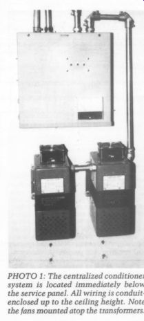
PHOTO 1: The centralized conditioner system is located immediately below
the service panel. All wiring is conduit enclosed up to the ceiling height.
Note the fans mounted atop the transformers.
... clamping action is not necessarily superior to the disk-type varistor of the same characteristic, except for this ability to divert large currents over time without failure. Numerous small units paralleled will not work because each unit will be slightly different within the tolerance windows of specifications. A transient event will tax the weakest, then the next weakest in succession.
Ruggedness cannot therefore be obtained by this method nor is there a means to sink the dissipation with the disk package.
The fusing of the power varistors is a slow-blow at 3A. The fusing of the follow-on varistors is 1A fast-blow. The first suppression stage will not protect the follow-on stages from repetitive peaks if the protection fuses are programmed to clear under similar event conditions.
A voltage peak transient, though thought of as a “spike,” is a complex high-frequency waveform and actually has an impedance. An incoming event on the service side may measure more than 100 ohm, common mode. When passed through a filter, its voltage is knocked down because the filter impedance works on it as it would on any other high frequency.
The filter itself acts as a suppressor and, in fact, that is precisely why it's there, as it will attenuate noise above a certain frequency. Two filters in series increase the order of filtration for all types of noise for which they are de signed, including “spikes.”' Wise to Replace Each filter presents, in turn, a different set of electrical parameters for an over voltage event. These Corcom units will carry 250V AC continuous, and fairly long-term pulses of at least eight times that. The power-line connection be tween two series connected EMI/RFI filters, and at the last filter output, look like good places to hook up some standard-duty varistors as back up. Thus two stages of filtration and three stages of transient suppression were designed for this system, with provision for repetitive events at the input. The principal reason for fuses in the varistor stages is not so much to protect the varistors, but to make the LED turn off. Make it a habit to check the LED status regularly, and always after a thunderstorm or observable line disturbance. If one or both of the protection fuses blow (as indicated by the LED), it is wise to replace all the varistors and both fuses in the indicated stage. Except for the power units, they're inexpensive. Your wiring layout should be such as to make this easy to do. Failure from stress may be imminent in an apparently undamaged device. See the section entitled “Managing Your Risks” later in this article.
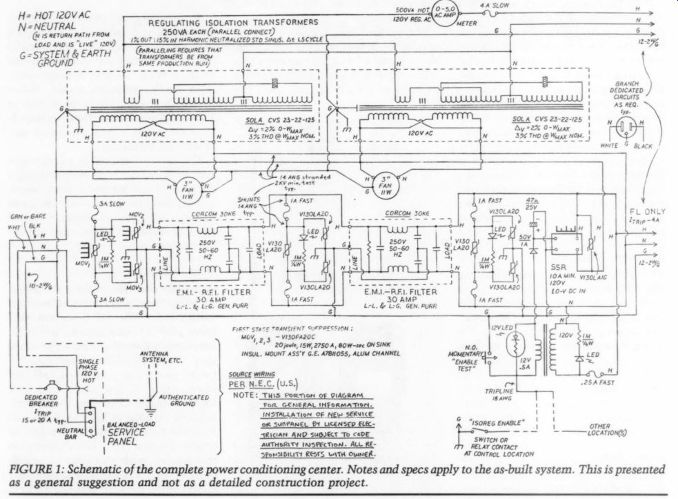
FIGURE 1: Schematic of the complete power conditioning center. Notes and
specs apply to the as-built system. This is presented as a general suggestion
and not as a detailed construction project.
Constant-Voltage Transformers
We used two 250VA transformers from Sola. They have the same serial number, so are connected in parallel, giving the effect of a single 500VA unit.
Henceforth I will refer to them in the singular, “transformer.”' (Sola indicates that the parallel connection is only possible when the units are from the same production run. Anyone designing from scratch should specify their VA requirement from a single unit.) The filter system is a relatively passive device. It just passes current, attenuating junk that happens to appear above its cutoff frequency. A constant voltage transformer will maintain a specified line voltage output for a given fluctuation window of input voltage and thus is a dynamic conditioner.
The wrong kind of transformer is worse than none. An isolation transformer offers the advantage of disrupting direct conduction of “disturbances” owing to the fact that input and out put are inductively coupled. Noise could still get through by capacitive coupling, except that the transformer has double, and often triple ferro-static shielding, which knocks down the capacitive coupling considerably.
A good isolation transformer works like a very effective filter. However, an ordinary isolation transformer will not regulate line voltage and will not necessarily pass a sinusoidal waveform which is important for feeding the linear power supplies that appear in audio equipment.
The constant-voltage transformer works like an isolation transformer in that it inductively couples and has triple shielding. However, it also has a neutralizing winding and storage capacity which allows it to produce a sinusoidal wave with low harmonic con tent. It is not a simple isolation-type transformer.
If the line voltage should vary to high or low amplitude for a sustained time, the transformer will support the load at a narrower voltage window, within the current capability of the transformer.
Nominal voltage variations are not the enemy of switching power supplies, but linear supplies will react to variable in put with variable output (linearly, of course). The constant-voltage transformer will see you through nominal voltage variations in a sound system and will improve noise performance as a filter stage.
-------------

TABLE 1: POWER CONDITIONING PARTS LIST (COMPLETE)
Power Varistors: GE V130PA20C
Power Varistor Mounts: GE A7811055, sink on heavy aluminum channel.
Standard Varistors: GE V130LA20A, B, or (preferably) C (or equal by others-Radio Shack 276-568).
Standard Varistor (at relay snubber): GE V130LA10A, B or C (or equal by others-Radio Shack 276-570).
EMI/RFI Filters: Corcom 30K6 30A general purpose--Current model number is 30Vk6; also available in 20A as 20VK6 and 10A as 10V K6.
ISOREG Transformers (Constant voltage, Ferro-Resonant): Sola CVS 23-22-125. Note: Installation manual for current models may require bonding of neutral-to-ground at the secondary.
The setup shown is balanced line with neutral-above-ground, as indicated. See text for details.
Solid-State Relay (SSR): Magnecraft W6110/DSX-1 (or equal by others; 3-32V DC opti-iso input, 10A zero-switching 60Hz output, hi-transient w/internal snubber; output current rating must equal transformer current rating x 2).
SSR Heatsink: use manufacturer-recommended or fabricate from heavy aluminum channel- relay must have adequate cooling.
Meter: Shurite 75032 (0-5 ACA) or equal (current range must cover that which totally includes the transformer output current rating).
Really PS Transformer: any small 120V primary with secondary up to and including 24V, vA or more will do. This is a 12v, 450mA unit (Radio Shack 273-1365).
Fans: Radio Shack 273-242 (or similar 120V AQ).
Wire at varistor Connections: use largest gauge practical, but not less than 16 AWG with an insulation rating of 2kV minimum test.
Wire at Transformer: follow instructions in installation manual, which may specify also hi temperature insulation if fans are not used.
Be sure to use silicone heat-sink grease. Mica insulators are provided with the power varistor mounts. The SSR does not require an insulator.
Resistors at varistor Shunts: 1M-ohm, 0.25W or more, 10% carbon composition is fine; LEDs run dim, but this is desirable.
Rectifier and Capacitor at Relay PS: rate for voltage at secondary with the usual derating factors-C value not critical (47 to 470uF, is okay); 1N4001 is adequate for the diode.
------------------
A Healthy Field
The nature of the constant-voltage transformer is such that it is fully saturated, the flux-density being high regardless of the current drain at the secondary. Thus, the unit will dissipate nearly as much heat while idling as it does under full-load conditions.
Ever the conservative, I decided to fan-cool the units and turn them on automatically upon demand. (This is yet another advantage of centralizing the conditioner system. I punched the top covers to admit fan-blown air, and the confinement of the wiring compartments makes the fans noisy. The units stay cool all over but are located where this cannot be heard.) The filter chain output is 'live' all the time, but the input to the transformer is switched. I use a zero-switching solid-state relay with an output cur rent rating of twice the maximum running rating of the transformer (inductive instantaneous turn-on current is, of course, high).
The relay should be heat-sunk and have an internal R-C snubber, which is augmented with a V130 outboard varistor. This relay is a 2-32V DC input unit connected from a simple half-wave rectifier power supply. With the 12V supply transformer, the shorting contact can be 100' away using the specified 18 gauge tripline, and I suspect much further distances are well within practicality, even with smaller gauge wire.
You cannot harm the transformer by drawing too much current. The output voltage will collapse, but it will not be damaged. I put in the ammeter and fuse as a means of immediately identifying the current limit based on the published specs for the transformer. We have a really big multi-amped system and are not finished experimenting with just how much we can tax the ISOREG part of the circuit.
If you should decide to use a constant-voltage transformer, don't skimp 5 S if you can help it. The dollar to current rating ratio of this type of transformer is high. If you can support the whole system from ISOREG, so much the bet ter. If the economics are such that you must downsize the transformer, consider confining part of your load to the filter circuit alone.
These transformers throw out a pretty healthy field. Audio equipment must be distanced from them, which is yet another good reason to centrally locate the conditioner.
A Word About Crowbars
[…] will not clamp below the operating voltage. I believe crowbar devices are not suitable, al though they have been used for the purpose extensively.
Gas discharge tubes (GDTs) seem especially attractive for diverting repetitive events because of their ability to handle current. GDTs are crowbar de vices. They may clamp the voltage well below the operating voltage and hold it there for a specific time interval. This is undesirable, as it represents trading a repetitive transient for a sag event.
GDTs are not as fast-responding as varistors. […] and labor-intensive to implement, but I believe it is right.
Not Done Yet
The simplified schematic diagram in Fig. 2 shows a power-switching unit for the sound system. No total-control power system would be complete with out this. The original project which in cluded the filters and varistors also had a relay system similar to this. The time-delay relays and two of the SSRs were salvaged from that unit. Now we have four separate power supply lines to switch: ISOREG instant-on-delay-off, ISOREG delay-on-instant-off, FL only instant-on-delay-off, and FL ONLY delay-on-instant-off.
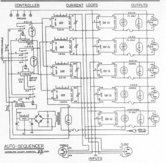
Is it possible, since the conditioner is centrally located, that the lines now running from the conditioner to the equipment location are susceptible to RFI pickup after the filter? What about filtering individual pieces of equipment against each other? Preferring to leave little to chance, especially having gone so far already, the switching unit will provide for a stage of filtration at the output of each SSR, as the diagram shows. Note at this point that bidirectional zeners are used in stead of varistors. They have a more idealized clamping characteristic than varistors, so will enhance the transient clipping action but are not as rugged.
Here they don't need to be so rugged; the preceding circuit protects them.
Managing Your Risks
L. B. Dalzell has advocated the use of gas discharge tubes in these pages. I agree with him about the ultimate protection provided by such devices properly applied. I differ with him in terms of the risk-management criteria, and the prospective builder of a power conditioner must choose his criteria.
The GDT will handle high currents associated with diversion of repetitive transients. GDTs are “self-healing” in the sense in which Mr. Dalzell uses the term. If the only criterion decided upon is transient protection, use them. But “power conditioning” involves criteria other than transient protection alone.
Real-life transient events are high frequency noise phenomena, and the use of multi-stage EMI filtration must not be discounted in their suppression.
If an event should occur causing the power varistor fuse(s) to blow, I have two filters and two stages of follow-on protection. That's why multi-stage suppression is there. The equipment is not completely at risk just because one of the fuses blow in any stage.
The fuses, ostensibly advocated as a means of 'protection,' must be thought of in terms of “detection.”' You could rig up a solid-state relay to trigger an audible alarm if you wanted to go to this extreme, in lieu of, or in addition to, the LED. As Mark Waller has pointed out in his book, there are countless devices in use today which have already sacrificed their protection, and the users don't have any way of knowing it. (Commercially available “power strips' and 'power centers” touting power line conditioning capabilities but having no status indicator, are potentially deceiving, and a look in side a typical example reveals the truly naive nature of its approach to risk management design.) I have indicated that when a fuse blows you should replace the varistor(s). The power varistors, in particular, may be OK in the event of fuse clearing. My fuse values are, I think, very conservative. The fuses do protect the varistors. If the power varistors are not apparently damaged and if the back up stages remain on-line, don't feel that you must change them.
If the input stage and a backup stage blow, you've been hit hard, and the power varistors probably should be replaced (check the continuity through the filters). If you suspect any stage using a disk package, run down to Radio Shack and get some more. The key is that you must go look at your LED indicators, just to make sure everything is OK. If you don't use LEDs, don't use fuses, but be sure the varistors are contained in a housing in case they shatter.
In terms of overall performance, I would rather be notified that my protection had failed than have an under voltage event, or even a blackout, every time a severe surge happened to come on line. My risk-management criteria would be wholly different if I had but one stage to rely on. I would then concur with Mr. Dalzell, and place over voltage damage above all else. I spent more sweat and tears (and money) on a system which did not require this from me. That is what “risk-management” in engineering is all about.
FIGURE 2: Conceptual schematic of the power switching unit being rebuilt
at the time of this writing. Provision is made for both sequencing functions
to control both conditioned power inputs.
-----------------
TABLE 2--POWER CONDITIONING
PARTS LIST (CONCEPTUAL) Delay on Make T-D Relay: Magnecraft W388ACPSOX-44, adj., time to 180 sec; 120V AC in Form 2C, 12A, 120V AC; or functionally necessary equal.
Delay on Break TR-D Relay: Magnecraft W388ACPSRX-4, adj. time to 180 sec; 120V AC in Form 2C, 12A, 120V AC or functionally necessary equal. D-O-B relays are constantly powered and use an external switch for on-off control.
Refer spare contracts to external; slave SSR current loops of any number may be so controlled.
Solid-State Relays: Magnecraft ASX series Class 6,120V AC input units, or equal, size output cur rent ratings for anticipated loads.
Filters: Select current ratings for anticipated loads. Note also that specialized units are available for loads handling digital (consult Mallory catalog).
All fuses and switched circuits are monitored with 120V neon pilot lamps.
Bi-directional zeners are harder to find than they should be. Motorola offers a 130V breakover unit and the author is in search of others.
The DC power supply assures correct voltage for all control relays. “Kill” and “standby” are actually relay controlled and will draw on this supply.
Remember that FL ONLY and ISOREG neutrals are NOT necessarily at the same potential.
Remember also that bonding of neutral to ground at any point in the FL ONLY line after the conditioner will short out normal-mode protection in the filter chain.
----------------------
No Comparison
The power varistors have been the first suppression stage in our system for five years, most of that time without fusing. Some severe event could have come down the line that would have destroyed them, but there they are, in tact and doing fine. I have the peace of mind knowing that they won't clip below the 120V line voltage.
You only have to size your filters and circuit fuses to handle just the load(s) of interest. The basic requirement, of course, is that you dedicate the filtered system to the equipment you want to protect. I chose the panel breaker be cause I wanted that whole circuit for things in addition to the sound system.
A centralized unit like this will be rightly governed by house-wiring codes, a requirement that I understood and was willing to satisfy. Several branches run out from the filter chain, involving considerable 12-2w/g Romex runs (“easily” done because we have a basement and can access the entire house with “new electricity”). The ampere rating for the filters was chosen on this basis, bearing in mind that service panel breakers are not sharp-cutoff devices. In any event, I recommend some current derating in the EMI filter(s).
In view of Gary Galo's observations concerning improvement in the sound of the hi-fi, I feel certain that I should, in principle, address this. Once you put in a power conditioner, it is not easy to make listening comparisons with any semi-objective reliability. You either have the system wired up to the power conditioner or you don't.
Results
Personally, I think the power conditioning makes a big difference. The whole idea is to attenuate noise and provide a stable operating environment, even when EMI and line voltage variations occur in subtle forms. I am satisfied that this advantage derives, though I will not pretend to demonstrate it categorically.
In fact, I have not obtained recording devices to monitor conditioner activity.
Equipment and methods are available which would give graphic illustration of the effectiveness of the conditioner.
While this could prove interesting, I have little doubt that, qualitatively speaking, I am constantly channeling garbage away from our audio system.
I will let anecdote suffice. We used to get all the pops and noise. We used to pick up radio, buzzes, and hums. We used to worry about lightning and what was going on in the distribution in the summertime. No more.
REFERENCES
1. Bishop, Anthony, Solid State Relay Handbook with Applications, Howard W. Sams, 1986. SSRs should be used for all really important power switching. This book is highly recommended to the audio amateur planning system power control.
2. Dalzell, L. B., “About Noise,” TAA 2/91, p. 10. Good coverage and interesting observations. Dalzell also addresses equipment grounding and other ways noise gets in.
3. Galo, Gary, “Ask TAA,” TAA2/91, p. 46.
4. General Electric, GE-MOV Varistors Voltage Transient Suppressors, Pub. No. 200.60. I have an early 100-page document. Contact GE for current info.
5. Harris Corp., Transient Voltage Suppression Devices, 1991. Excellent overview of modern theory with attention to fine points. TCE Special Products Division, 2000 Clements Bridge Rd., Deptford, NJ 08096-2088.
6. Mallory catalog contains specs for Corcom filters. Note the variety of designs available.
7. Orr, William I., W6SAI, Radio Hand book, 23rd ed., Howard W. Sams, 1987, Chapter 11. This reliable standard is a first rate electronic experimenter's source book. Mostly devoted to radio, it contains a large amount of basic electronics and construction practice information. It is a good source for power supply design.
8. Waller, Mark, PC Power Protection, Howard W. Sams, 1989. This book is “must” reading for audio amateurs. While it ostensibly addresses computer operating environments, it covers the whole subject of operating power for sensitive loads. It is a good place to find a complete discussion of theory concerning AC power, problems with it, and how to clean it up.
9. Sola Electric, Unit of General Signal Sola Constant Voltage Transformers-Operating and Service Manual, 1982. 19-page document provided with the transformers. Contact Sola, 1717 Busse Rd., Elk Grove Village, IL 60007, (312) 439-2800, for information on current models and applications.
ACKNOWLEDGEMENTS
The 'we' in this article refers to myself and my wife, Barbara, who has always contributed mightily to the success of our “stereo.”' My thanks to electrical engineer Keith Fager.
----------------
About the Author: Paul Graham is an Architectural Consultant specializing in Life Safety codes and door and hardware specifications. With his wife Barbara, he has built two generations of floor-standing speaker systems, the current one being fully multiamped using op amp active crossovers (SB 4/87) and beam power high-frequency amplifiers (after a classic RCA circuit) of his own design and construction. A resolved tube-phile, he is currently building Rozenblit's Mac design for his D'Appolito configured bass-mids and is designing a third order all-tube cross over, after Waldron, for the upper crossover point.
-------------------
Also see: