A 35W POWER AMPLIFIER FROM SALVAGED PARTS
ABOUT THE AUTHOR: John Adelsbach graduated in 1970 with a BSME from Cal Poly. After a stint at Westinghouse Electric, he returned to school and was awarded a M. Engr. from Cal Tech in 1976. He then joined Hewlett-Packard, working on plotters, disk drives, PCs, and terminals. He currently is the program manager for the HP800 and 900 series of client/server workstations. Other interests include video, software writing, and long-distance running.
THE MOST ATTRACTIVE aspect of audio amateurism, in my opinion, revolves around applying the combination of art and science. Audio's captivating blend of engineering, industrial styling, and musical event is without equal. My hands-on experiences with developing audio equipment to generate the magic of music have intrigued me for nearly 30 years.
In this pursuit, I have designed, modified, and analyzed more power amplifiers than I can remember. I have used the Dynaco ST-70 as the source of parts for one of my most frequent patients in elective surgery. Recently, the Vacuum Tube Audio (VTA) circuit and PC board have also been used successfully. Here is another example of applying these parts; one of my most rewarding case studies to date.
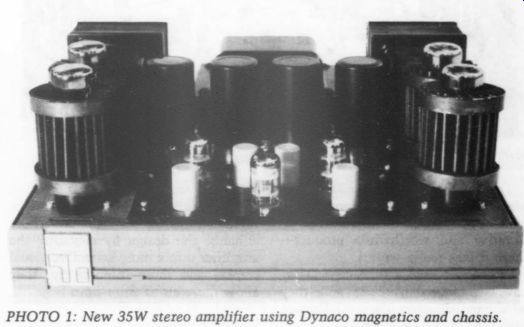
PHOTO 1: New 35W stereo amplifier using Dynaco magnetics and chassis.
Planning
My objectives for this project were to create an amplifier that:
Is visually striking;
Looks, feels, and acts like a top quality commercial product; and Makes innovations in ease of setup and use.
To accomplish these objectives meant: a) developing a fresh new signal circuit and power supply, b) restyling all aspects of appearance, and c) designing and building an LED-based tube alignment and monitoring system.
All these changes were carried out with the highest quality materials and construction techniques I could find.
Overall
Starting with a stock amp, I salvaged the top and bottom chassis pieces, and saved the transformers, both output and power. I threw away everything else. Any further identification this amp might have with the Dynaco lineage would end there.
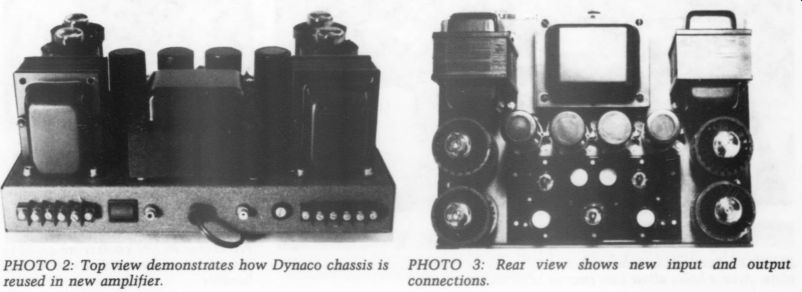
PHOTO 2: Top view demonstrates how Dynaco chassis is reused in new amplifier. connections.
PHOTO 3: Rear view shows new input and output
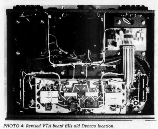
PHOTO 4: Revised VTA board fills old Dynaco location.
The visually arresting PEARL coolers adorned each output tube. (I must compliment Bill Perkins of PEARL on an innovative and worthwhile product--these things really work.) I have not used a tube cage. They have two marked disadvantages--they are thermal disasters (the stock Dynaco cage was only 25% open to air flow) and they obscure the view of the components beneath.
On the underside of the chassis, I added four elastomer feet, replacing the metal bumps on the original. These enhance the design by elevating the amplifier into a more attractive visual stance, and more importantly, they allow more air to enter from beneath.
Circuit Details
Starting from the VTA PC board, I made substantial changes. Using computer-simulation models, I optimized the core VTA topology and operating points. I adjusted this new design only to the ex tent that I thought it made an audible difference. Overkill and brute force were out; engineering elegance and simplicity were watchwords. Keep the part count low and reliability will follow.
Restyling
I painted the chassis with Zolatone, the hard, durable automotive finish that looks remarkably like granite and I bonded a milled aluminum plate to the front of the old chassis. I recessed a rectangular “power-on” LED into one of the front panel accent grooves, thereby hiding it until it lit up when the amp was powered. I attached a commercial audio manufacturer's nameplate to the anodized gray-steel panel to accent the front and to yield a polished look.
The back panel was likewise completely reworked. I silkscreened heavy duty barrier blocks with speaker connection identification. I moved color coded, gold-plated phono plugs from the front to the back panel and added a high current rocker power switch in to an enlarged chassis hole, replacing the original slide switch. This not only looked better, but it worked well in absorbing the high turn-on current surges from the large power supply capacitors.
The stock transformers were vacuum...
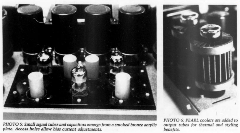
PHOTO 6: PEARL coolers are added to output tubes for thermal and styling benefits.
...dipped in potting compound to eliminate lamination distortion and acoustic hum. I then coated them in satin-black epoxy and mounted a smoked bronze acrylic plate over the main PCB. This plate cleaned up the appearance and safely enshrouded high voltages, yet remained visually transparent to the LED indicators mounted underneath.
The raw PCB was, in turn, painted black to complete the clean, uncluttered look. I painted the tube sockets baby blue, just for fun, thereby matching the color of the adjustment pots.
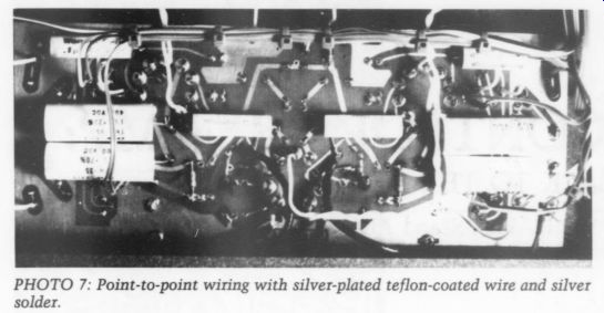
PHOTO 7
The four 1,000uF power-supply capacitors were mounted with gold-plated ...
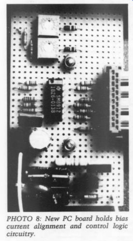
PHOTO 8: New PC board holds bias current alignment and control logic circuitry.
... clamps. All the mounting hardware I used was stainless-steel hex-head screws. Threaded inserts mating to ma chine screws replaced the funky, original sheet-metal fasteners.
Alignment and Tube Monitoring
I mounted two switches on the top surface. These set the functioning state of the four LEDs mounted on the four corners of the main PCB. All pots (four bias-adjusting pots and two AC balance pots) were made accessible through small holes in the acrylic cover plate.
When the momentary contact switch is moved in one direction, its respective LED indicates that the plate current pot has correctly set the bias. Moving the switch in the other direction injects a 60Hz signal into the amplifier.
This signal is used as an input in set ting the phase-splitter stage to equal amplitude. The AC balance pot is then moved to the lowest distortion position as indicated by the relative brightness of the two LEDs serving that channel. The final function of the LED switch is in its default condition. When the switch is returned to its normal upright position, it will light continuously when its respective output tube drops to 80% of the originally set plate cur rent-an indication that the tube needs replacement.
All these LED control functions are realized on a small secondary PCB mounted inside the chassis, and routed to circuits on the main circuit board using ribbon cable.
Results
I have attempted to create a design that exploits the beauty and inherent industrial high-tech look of tube power amplifiers. Along the way, I tried to create new styling elements that I had not seen in commercial products before. Sonically, this design creates a musical experience for me that is as satisfying as any I have had from an amplifier in its power class.
SOURCE
PEARL Perkins Electro-Acoustic Research Laboratory 2510 - 19 Street SW Calgary, Alberta T2T 4X3 Canada Telephone and FAX (403) 244-4434 (see ad in GA 1/90, p. 46)
Also see: