A NEW CONTROL PREAMP: BACK TO THE FUTURE PART 1
WITH AN AUDIO and telecommunications career that began in the early 1950s, I have seen many changes, with most developments advancing the art and science of high-quality sound re production in that time. It's been a lot of fun, watching the various technical arguments battling to and fro between the audio giants and occasionally, tossing in my own modest two cents.
Regrettably, those halcyon days have gone forever. Hi-fi is now a consumer durable, like washing machines, and subject to all the hype you expect when this year's model with the latest radical innovation must be sold to a gullible public.
I watch with increasing bemusement (and occasional irascibility, as my respected good friend, our Editor, will testify) at the growth of an industry bedeviled with myths and magic, aided and abetted by a significant majority of sycophantic re viewers. He will know only too well that I have little time for fancy cables, super components, and so on ad nauseum. My occasional ill-tempered soundings off in our private correspondence will testify to that. To me, audio engineering is and al ways will be the scrupulous, painstaking application of all the sciences (and that includes psychology) coupled with well established engineering techniques that have stood generations of designers in good stead for more than a century, and will continue to do so.
This little polemic is a necessary prelude to design thoughts on a subject that seems to have suddenly become passé, taboo even. It is a great mystery to me, at a time when the range of program sources avail able in the home has become even wider and more variable in quality, that the functions offered in the so-called preamplifier seem to have dwindled to virtually nothing. Like Alice, it seems to be shrinking at an alarming rate and destined to disappear altogether. One day, we will be presented with a glossy box with one knob on it labeled 'volume' although I strongly suspect someone, somewhere, is enthusiastically working on eliminating that as well.
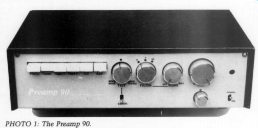
PHOTO 1: The Preamp 90.
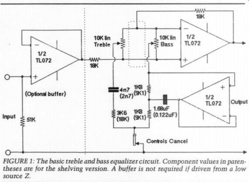
FIGURE 1: The basic treble and bass equalizer circuit. Component values in parentheses are for the shelving version. A buffer is not required if driven from a low source Z.
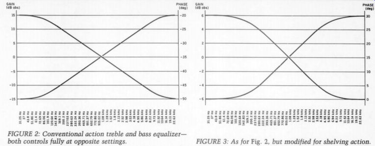
FIGURE 2: Conventional action treble and bass equalizer--both controls fully at opposite settings. FIGURE 3: As for Fig. 2, but modified for shelving action.
The inclusion of features, such as what used to be called tone controls, and filters (Optional buffer) of various types seems to be almost pro scribed with near religious fervor. Yet, even with the alleged perfection of the compact disc, many program sources are far from satisfactory in a qualitative sense and this applies particularly to old analog reissues on the new medium. It exposes faults that were masked in the old mechanical system, the LP; and the use of
early designs of capacitor mikes with a rising frequency response, inherent in a large diaphragm capsule, revealed in many cases an objectionable emphasis in the highs.
Many old analog tapes also have a high distortion content at the upper end of the spectrum. All can be quite unpleasant and simply scream for the introduction of a little amplitude manipulation, perhaps even a steep-cut, low-pass filter, and preferably variable. Traffic noise at the venue, hitherto concealed by a skillful cutting engineer, suddenly becomes obtrusive and desperately needs a selective high-pass filter.
Everything I have described suggests the desirability of some form of amplitude response correction, the nature of which depends on the type of aberration you wish to ameliorate. Admittedly, you can never correct it completely, but you can improve the subjective sound quality, which is what this article is about. If it seems already like decadent thinking, turn to the next article in this excellent issue. What I will say is not for you and may be interpreted as the archaic ramblings of a reactionary.
The Control Preamp
I intend to look again at various types of tone controls, but my preference is for the professional term of equalizer. Each of my thoughts will be accompanied by a circuit and eventually, the best of them will be combined into a full-function preamplifier that my colleague Alan Watling and I have been working on for more than a year. As far as I am aware, most of the circuitry is original and uses the latest design techniques, and so is unlikely to be found in any commercial product.
However, I make no secret that the one commercial-quality preamplifier that still provides extensive equalizing facilities has been my model. This is the respected British ‘Quad, ’ the manufacturer who gave us that superb full-range electrostatic speaker, the ESL63. If the function of anything I describe bears more than a passing resemblance to one featured in the Quad range of preamplifiers, it is no accident. But that is where comparison ends, for the circuitry is significantly different, even if the functions are similar.
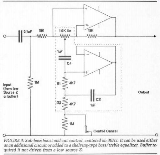
FIGURE 4: Sub-bass boost and cut control, centered on 30Hz. It can be used either as an additional circuit or added to a shelving-type bass/treble equalizer. Buffer required if not driven from a low source Z.
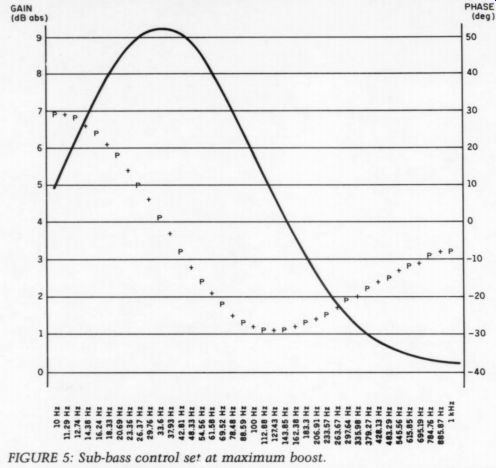
FIGURE 5: Sub-bass control set at maximum boost.
[12]
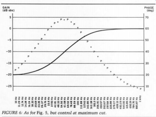
FIGURE 6: As for Fig. 5, but control at maximum cut.
First, a brief reference to what my radio ham friends call the ‘front end, ’ although it is likely this may disappear soon. User enthusiasm keeps the LP alive in the consumer world rather than vested commercial interests; and so, an input stage is still required that not only lifts the signal to a workable level to avoid corruption by […] an internationally agreed standard, known as the RIAA/IEC curve. Refer to TAA 2/90, in which I dealt extensively and in considerable detail with this important area of design. I offered nothing very original in the way of circuitry; indeed, provided great care is taken over accurate circuit parameters, a simple series feedback equalizer type is more than adequate. Over complex circuitry does only one thing, as far as I can see-simply adds to the cost.
If the source material were worth the extra effort and expenditure, it might be justified. Generally, it is not.
Circuit Techniques
Let me now deal with the matter of equalizing the amplitude response if the sound of the program source indicates deficiencies or excesses in the spectrum at either or even both ends of the spectrum. The old type of tone control, with treble and bass cut or boost, a la Baxandall, has reigned supreme for almost 30 years and may still be found in hypermarket stack systems.
I have designed a circuit for those who yearn for something similar. While its functions are similar to the ubiquitous Baxandall, it uses circuit techniques far from commonplace when my good friend Peter created his popular circuit configuration. I have introduced for the first time, I think, the concept of a general impedance converter or GIC. This is a design technique in which you can make a particular circuit element-say, a capacitor-behave as something else. In this case, it functions as an inductor. This results in a simpler (and more cost effective) circuit with useful new virtues.
It's inherently symmetrical and the shape of the bass and treble rise curves are exactly matched in the cut mode. In the electrical center position of the two adjustable controls, the reactive elements are nonfunctional, so much so they may be switched out of circuit altogether with a one-pole on/off switch. The circuit then becomes a simple buffer amplifier, non-inverting and with unity gain. It must be fed from a zero (or very low) source Z; sometimes the previous drive circuit may automatically provide this.
In the sample circuit, I have included a straightforward buffer amplifier of unity gain, but the complete preamp has an option of 6dB of gain. The ‘inductor ’ is actually one in series with the two 1.8 k-ohm (3.6 k-ohm) resistors for the full tone control version or 9.1 k-ohm (18.2 k-ohm) for the shelving version. The value of the simulated inductor is ‘easily calculated, being the product of the two resistors (in kilohms) and the capacitor in microfarads.
As shown (Fig. 1), it provides for levels of cut and boost around a central point of a nominal 1kHz, of 15dB maximum at the extreme ends of the spectrum. Quite orthodox in action (Fig. 2). However, I can suggest that a more acceptable modern modification might be a conversion to what is known as a ‘shelving ’ control.
The action is the same, but the range is now strictly limited to say, about * 6dB, with a 'shelf' appearing in the response curve at about midway between the central point and about a decade above and below. Since the basic circuit is identical, but with new values (in parenthesis) the enthusiastic experimenter can try both (Fig. 3).
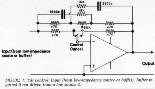
FIGURE 7: Tilt control. Input (from low-impedance source or buffer). Buffer required if not driven from a low source Z.
One other circuit that may be included separately, or as an integral part of the shelving tone control (but not recommended for the orthodox version), is an other type of cut-and-boost control, but confined to the extreme bottom end of the spectrum (Fig. 4). Centered around 30Hz, a sub-bass equalizer can provide a useful correction feature (Fig. 5). It can add a small rise in the area where most budget loudspeakers are beginning to fall off, but it must be limited to no more than + 9dB.
Its complementary cut function (Fig. 6) also behaves as a useful rumble or traffic noise filter, or for minimizing the characteristic ‘honk ’ that afflicts some room/ speaker placements. If it is added to the shelving tone control, an additional 10k linear pot is all that is required between the invert and non-invert inputs of the differential mixing amplifier, to vary the effect of the low Q tuned circuit. In the physical center, the reactive components are again nonfunctional and the passband is flat.
To switch out altogether, it may be taken to the common switching-out point (see the dotted area of Fig. 1). The 1 M-OHM resistor preserves the DC conditions for the GIC op amp. Again, as will be seen, it shares a common ancestry with the bass control already described except an additional series capacitor converts it to a low Q, broadly tuned circuit. A first order, high-pass passive filter is added if used on its own and not with the bass and treble equalizer. As before, the tuned frequency (around 33Hz) is easily computed with slightly more complicated math.
f, = √ 25,330 /|C1 C2 R1 R2)
All resistors are in kilohms and capacitors in microfarads. The Q, and thereby the sharpness of the peak, may be raised by increasing the ratio of C2 to C1; but the product must always remain the same. For example, find the product of the two Cs, then divide this by a larger value for C2 to obtain the new value for C1. Alternatively, to lower it, divide by a smaller value. Some small variation in the f, is also possible by altering the ratio of R1 to R2; but here again, it is the sum of the two in series that must al ways remain constant. Easy.
One final version of the shelving type of equalizer earns the apt name of a tilt control (Fig. 7). This works in a similar fashion to the shelving bass and treble type, but uses only a single control acting symmetrically on both sides of a common axis point-again, in this case, nominally 900Hz.
Suppose, by way of example, the sound is over-warm and lacking in brilliance? Rotating the control in a counterclockwise direction accentuates the high end with a shelf-type amplitude change, with a complementary attenuating action below 900Hz. This is usually limited to a maximum of 6dB, literally 'tilting ’ the spectrum response one way or the other.
Conversely, what if the sound is over bright and lacks warmth? Rotating clockwise in varying degrees will lower the high end and raise the low end- but again, to a maximum of 6dB. This is my favorite. It is very effective in small amounts applied judiciously to the range of program sources to which I have access. Again, the physical center is also the nominally flat position, but it too, may be switched out of circuit. It does introduce a phase inversion. Figure 8 shows its similarity to the action of the more complex shelving control.
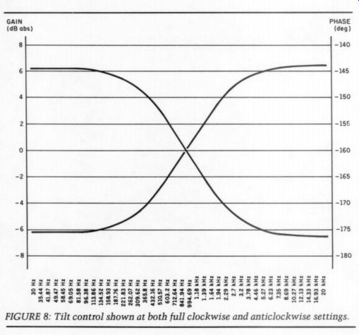
FIGURE 8: Tilt control show at both clockwise and anticlockwise settings.
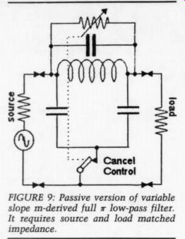
FIGURE 9: Passive version of variable slope m-derived full pi low-pass filter. It requires source and load matched impedance.
Now, we come to that type of amplitude bender that is increasingly rare- the variable steep-cut, low-pass filter (Fig. 9). A high proportion of the most objectionable artifacts in a program source are above 5kHz. In the old 78 days and with some less-than-ideal pressings of LPs, this includes surface hiss and the inevitable tracing distortion. In these instances, the listener is presented with two alternatives: tolerate the defects for the sake of corrupted highs or introduce high-frequency selective filtering until virtues are balanced with the defects and acceptable.
My preference is unashamedly for the second option, so it is no accident that this feature has had more time spent on it in the design process than all the others combined.
Alan Watling (my collaborator) and I, as well as other Golden Ears, have made copious comparisons of subjective notes. The design has the following features. A switched selection of one of three frequency ‘break ’ points, nominally 5, 7, or 10kHz. It also has a variable slope control. So if, for ex ample, you decide to begin cutting off the high-frequency components at 7kHz, you can vary the effect by altering the slope from a maximum of about 24-26dB/octave to virtually nothing in the full counterclockwise position. If the control has an integral switch, the filter may also be switched out of circuit completely by the pure at heart.
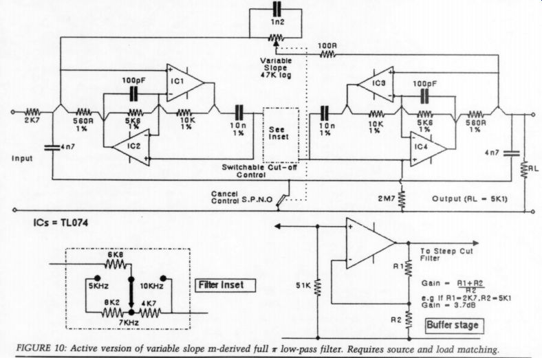
FIGURE 10: Active version of variable slope m-derived full = low-pass filter. Requires source and load matching.
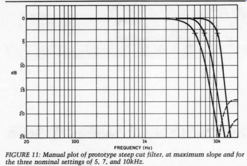
FIGURE 11: Manual plot of prototype steep cut filter, at maximum slope and for the three nominal settings of 5, 7, and 10kHz.
How Does It Work?
Despite its apparent complexity, it is really a modern version of what was (and still is, I assume) called an m derived, full-section, low-pass filter.
The passive circuit it simulates is shown in Fig. 10. This has not only selected nominal -3dB break points, but also has zero-pass nulls in the stopband.
These null points are determined by the 'm' factor in the equation, which may be obtained from any good text book. In this instance, it is an octave above the break point. It has the virtue of potentially high rates of attenuation above the break point and is simple and ideally suited for our needs. However, to even suggest to any DIY audio enthusiast in the 1990s that an inductor needs to be wound guarantees a rush of blood to the head and my probable impeachment as Contributing Editor.
Some loyal readers of old might recall that I did use a simple single-frequency version of this filter in the preamplifier for my original 20/20 amplifier some 25 years or more ago. To this day, I have no antipathy to using a real inductor, so I have no feelings of guilt and still think it is the best way. This only shows what an unfashionable old reactionary I am (Fig. 11).
Happily, a circuit technique already employed earlier again comes to the res cue, an advanced variant of the impedance converter called a gyrator. Paul Marchese has introduced us to one version in TAA 2/90.2 In this instance, it is a resistor we persuade to behave as an inductor and because the inductor is ‘‘floating ’ above signal ground, two gyrators must be used tail-to-tail. Varying the value of the resistor means, of course, we can adjust the value of simulated inductance-an exceptionally valuable attribute, especially so if you wish to alter a particularly large value continuously. If you wish to pursue this technique even further, I recommend an excellent book, much thumbed at the University of Keele, England where I teach. This is Analog Filter Design by M.E. Valkenburg of the University of Illinois and published by Holt-Saunders.
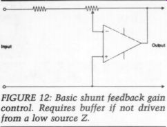
FIGURE 12: Basic shunt feedback gain control. Requires buffer if not driven
from a low source Z.
Controls
Let me talk a little now about an allied subject: gain or volume controls. You might be forgiven for thinking nothing original could be said about a simple gain (volume) control, but don't believe it. Almost two decades ago, a new de sign of hi-fi amplifier, the Cambridge P40 was introduced in Britain which employed for the first time, a control that included variable negative feed back. This is something designers have always found attractive and yes, since you ask, the ‘Quad ’ 44 preamplifier has its own version to this day. Both use a technique for simultaneously varying the passive input, as well as the feed back path in a straightforward shunt feedback amplifier stage (Fig. 12 is a basic configuration).
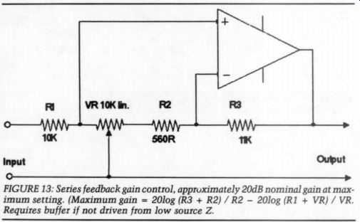
FIGURE 13: Series feedback gain control, approximately 20dB nominal gain at maximum setting. (Maximum gain = 20log (R3 + R2) / R2 - 20log (R1 + VR) / VR. Requires buffer if not driven from low source Z.
While this method functions acceptably, it does have a few inherent draw backs, not the least of which is that at maximum attenuation, the ‘ground ’ side of the control pot goes to a virtual ground point, not a real ground. This means that in practice, complete attenuation is never fully achieved. An alternative* with which I have been successfully experimenting instead uses series feedback plus passive attenuation and which Alan confirms works very well (Fig. 13).
The advantage of this technique is that the input is now to a real ground at the control's maximum counter clockwise position, so complete attenuation of the input signal is realized. By intelligent computing of circuit values, a close simulation of audio taper is attainable with a linear control. Within sensible limits, some gain is possible and my sample version is designed for a maximum of 20dB. For those who regard non-inversion of the signal as necessary, it achieves that, too.
This more or less completes my survey of the various circuits that may be tried by any ambitious experimenter.
These circuits lend themselves ideally to CAD as well as computer simulation; but in all instances, Alan has made bench mockups to check them out as well. In all cases, the computer simulation graphs have virtually matched the actual test results. One exception is for the steep-cut filter, since the computer simulation could not give an adequate indication of the effects of all three turn over points together. This was plotted manually on the prototype.
(Continued in our next issue.)
REFERENCES
1. Williamson, Reg, 'Understanding the RIAA, ’ TAA 2/90, p. 18.
2. Williamson, Reg, ‘A Variable Slope Hi Pass Filter, ’' Electronics & Wireless World, Aug. 1990.
3. Marchese, Paul, ‘High Performance Analog Circuitry for CD Players, ’ TAA 2/90, p. 8.
4. Williamson, Reg, ‘Circuit Ideas, ’ Electronics & Wireless World, January 1991.
NOTE: Reg Williamson and Alan Watling have collaborated on projects such as this for more than 32 years.
ABOUT THE AUTHORS
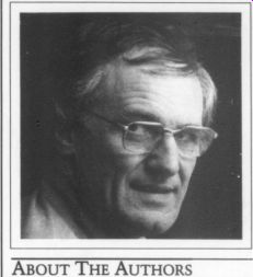
Reg Williamson has been designing audio hardware for more than 38 years and has been contributing to TAA since its inception 22 years ago. He was an engineering executive with the telephone utility British Telecom, but in 1985, after more than 40 years of unbroken service (apart from a short spell in the army), he decided to take his pension, complete with a medal and citation from the Queen. Now, with his increased leisure time, he indulges his passion for music, good food, and wine.
However, he also teaches electronics part time at the University of Keele in Stafford shire, England, attempting to convey to a younger generation his enthusiasm for sticky technical problems, which burns as brightly as ever.
The microphone is a capacitor type Williamson designed and made in 1962. It won him a prestigious prize from his professional association, the Institute of Post Office Engineers (as it was then known) and the technical paper was later published in Audio in 1963--his first for an American magazine. It triggered many friendships in the US that he cherishes to this day.
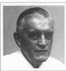
Alan Watling lives in Colchester, Eng land, in John Constable's country. Since he retired from a career in British Telecom, he has indulged his favorite pastime of water-color painting, but has spent many midnight hours making the prototype hardware from Reg Williamson's diagrams.
He is deeply suspicious of audio effects that have no measurable scientific causes, and he listens to his own equipment critically with ever-increasing enjoyment.
++++++++
Also see: