- INTRO
- EDITORIAL--Engineers' Retreat
- KIT REVIEW
- JUST LOOKING
- LETTERS
INTRO
John Adelsbach designs and creates a 35W power amp using the Dynaco ST-70. His only requirement in the design of this project was “engineering excellence and simplicity” -- an example of a project that is visually and audibly competitive to commercial high tech power amplifiers.
This is the second and final part of Reg Williamson and Alan Watling's design for a control preamp. Designed for the novice, the main focus of this project is ease of assembly. The more experienced assembler will appreciate the ability to alter the gains by changing values in two buffer amplifiers.
The Audio Engineering Society's 91st Convention is the topic of Gary Galo's article beginning here. The debate continues over listening evaluation techniques. This timely re port will provide information and in sight. Everyone has an opinion, see if yours is represented and what the reaction was at the convention.
Paul Graham discusses how he corrected a myriad of power inconsistencies by designing a centralized power conditioner. Two stages of filtration and three stages of transient suppression, channeled polluted power away from their sound system, telephone and home computer.
David Davenport reviews the fourth edition of the Loudspeaker Design Cookbook , and William Wiemann reviews the Mark V, TA3600 kit (see below).
Editorial
Engineers' Retreats
One of the pleasures of living in our town of Peterborough, New Hampshire is not only the scenery of two rivers meeting downtown and the view of our surrounding mountains, but also a private, 400 acre farm that for nearly a century has been a retreat for working artists in literature, music and the plastic arts. The MacDowell Colony is strictly off limits to ordinary mortals all year long save for one August Sunday when a medal is conferred on a distinguished artist.
On that day anyone with the price of lunch can attend the ceremonies which are generally entertaining, informative and culturally refreshing. The Colony was founded because Edward MacDowell needed a quiet place to compose. His compositions are a pleasant addition to American music in the well-behaved late nineteenth century European-aping style. His wife Marian was the real energy behind the idea to turn a farm into a major retreat for artists.
Every quarter a new group of some forty persons come to Peterborough to take up residence at the Colony to work on some favorite project. They each have a cottage of their own in which to work. A central residence offers sleeping quarters and meals are provided. All this is sup ported by a growing endowment, built over the years from contributions by successful artists as well as interested individuals who believe in supporting the arts.
Over the years the foundation has grown, and some forty cottages were built one at a time, sometimes by an interested group's fundraising efforts, throughout the untouched 400 acres. Talented folks of every description have spent uncluttered, uninterrupted weeks at the place with all their needs met without thought or care for life's necessaries.
The place has so many memories scattered about its paths through the woods and hills that lists of what has been written, finished, or begun there reads like an honors list of America's artists. The “our town” I mentioned above is, in fact, Thornton Wilder's play, Our Town, by now an American classic. Its drugstore setting, with its druggist narrator, was one Wilder visited often while at MacDowell. The book for Porgy & Bess was written at MacDowell by a couple who first met at the Colony, married, and returned to complete the classic there. Leonard Bernstein wrote parts of "West Side Story” during one of his many visits.
The value of MacDowell to American drama, art, music and literature is incalculable. A simple idea: give people with talent a place to work uninterrupted, and for an unbroken space of time and see what can be accomplished.
Why has it never occurred to anyone that American technology, which at its core is an imaginative process, needs a place of quiet for uninterrupted work-without telephones, faxes, business lunches or other distractions.
I know that companies send selected people on sabbatical study leaves, sometimes for up to a year. Such leaves are generally spent in some academic venue, which these days is not exactly a retreat from the frenetic world we all seem to inhabit. It seems to me that thinking time is becoming more and more difficult to find in our hyper-enabled world where one can send faxes from a laptop to a sales staff of 20 flying at 32,000 feet over Kansas City.
While the MacDowell Colony equips its cottages with a variety of appurtenances including pianos, print-making gear, potter's wheels and photo labs, audio engineering types need only bring a laptop and a few books for a three month stint that might produce something innovative if only they had the time and opportunity. Breakfast is ready for hours each morning for colonists, cottages are within walking distance and lunch is delivered to each doorstep every noon-time.
Every worthwhile human endeavor, it seems to me, requires such an environment for the best growth and development. I don't know what is happening these days at Bell Labs in New Jersey, but I devoutly hope that Judge Green's dismantling order hasn't forced AT&T into such a competitive mode that no one has the time or leisure to spend days or weeks just thinking. The largesse of the Bell Laboratories establishment when AT&T's “monopolistic status” gave it the “luxury” of pure research, has benefited every resident of this country in countless ways.
Not the least of these being the transistor.
Many companies who design and market audio equipment have made remarkable amounts of money over the half-century of modern sound development's growth. But no one seems to be investing in the future of audio--or putting aside any “seed corn” for what is to come next.
Lots of product development and market research but no one taking a larger look at the needs and the possibilities.
Can't more be done than merely getting the next new “breakthrough” ready for CES? Is audio forever to remain a hand-to-market annual cycle? And if we cannot find ways to start a MacDowell for audio technology, are the resourceful, promising people being given sabbaticals to do some original work and thinking about audio reproduction. I can think of several people whom audio has treated very well. Perhaps it is time for them to give something back.
-E.T.D.
Book Reviews
THE LOUDSPEAKER DESIGN COOKBOOK, 4TH EDITION Reviewed by David W. Davenport The Loudspeaker Design Cookbook, Fourth Edition, by Vance Dickason. Pub lished by Audio Amateur Press and avail able from Old Colony Sound Lab, PO Box 243, Dept. AA, Peterborough, NH 03458-0243, (603) 924-6371, $29.95 plus $2 shipping and handling.
WITHOUT A DOUBT, the book most reached-for when I roll up my sleeves to get serious about designing a new speaker system is Vance Dickason's Loudspeaker Design Cookbook. I'm not alone in this; the cookbook has been around for over 14 years and is now available in its fourth edition. The extensive changes in this latest edition are pretty evenly split between material on new subjects and additions to existing subjects. A new chapter covers drivers, as well as sections on types of enclosures not mentioned in earlier editions. Another first is the extensive use of computer-aided design techniques to illustrate many characteristics of sealed and vented enclosures.
Study the Diagrams
It seems that every book on loudspeakers has a chapter titled 'How Loud speakers Work.” The flavor here is a little different from the others however. It focuses on a view that will be of most interest to those of us wanting to build loudspeaker systems. For example, al most a full page is spent on discussing the significance of overhang and under hang in voice coils.
In addition to the in-depth treatment of the gap geometry, the section on mo tor system delves into the phenomenon of program current in the coil causing back emf, and therefore modulation, of the magnetic field. This leads into shorted turns and why they are used.
The section on the diaphragm covers such things as modes of resonance in a cone, and how directivity changes with frequency, as well as the effect of cone shape on the sound of the driver. It has more than you want to know about dust caps. Coverage of the suspension sys tem is limited to the surround and the spider-what more is there? The chapter on “Closed-Box Low Frequency Systems” provides all you may need to know about designing Infinite Baffle and Air (Acoustic) Suspension loudspeaker systems. As you might expect, it begins with an in-depth discussion of enclosure response and driver Q, including the meaning of Q and a description of typical sounds of different Qs.
Here Dickason draws on his own vast experience using LEAP 4.0 (Loudspeaker Enclosure Analysis Program by Audio Teknology, Inc.), and introduces its use extensively in modeling enclosures. Al though the examples shown are for a particular driver, experienced designers may want to study the LEAP diagrams to acquire general insight.
Did You Know?
For example, I have never read a better portrayal of the trade-off between damping and power-handling ability. The chapter is not all theory-for implementing a design you are given the option of using formulas or the complete set of Q tables, which are included. The effects of parameter variances are covered. In addition to the basic ones, formulas are included to determine efficiency and output power limitation.
I was glad to see examples-they are often needed to clear up nagging questions. As an additional assist to designers, guidance is provided for selecting a driver. To top it off, the effects of thermal deviation are handled, as well as an extended section on enclosure filling.
After this thorough treatment of the bas ics of a “simple” closed box enclosure, more advanced material is introduced.
For instance, the section on electronically assisted closed-box systems points out some of the pitfalls in an apparently attractive approach to a closed-box system design. You can read material on mass-loading modifications, as well as considerations of designing a loudspeaker containing compound woofer systems.
I accepted reviewing the fourth LDC because I was looking forward to new material on bandpass enclosures. And I was not disappointed-the treatment is exceptional. Instead of considering the bandpass enclosure to be a type of its own, it is addressed here as a closed-box system-with the addition of an acoustic filter in series with the front radiation of the driver. There's more to it than just a few tables and formulas-- the technique is discussed in detail. For example, did you know that, contrary to its name, the bandpass enclosure has substantial output outside of its range and therefore should be used with an appropriate adjunct electronic filter?
Illustrate the Differences
I hate to close a chapter on a sour note, but I was disappointed with the section on the aperiodic enclosure. To be fair, this type of enclosure has not benefit ted from a rigorous analysis by Thiele or Small. Thus, treatment of the aperiodic enclosure was left wanting in com parison to the very thorough, analytical material on the closed-box enclosure.
The third chapter, “Vented Box Low Frequency Systems,” is a repeat of the second-the complete story. It starts with a short history, and discusses driver Q and enclosure response. Of course, because you can't control the Q in a vented design the way you can in a sealed box, the objectives are different.
The discussion on woofer selection initiated in the previous chapter is expanded upon to include determining what kind of enclosure would be best for your driver. The vented box design is associated with alignments; a term that is bandied about without really considering what it means. The introduction to the alignments in this chapter is as good as any I have seen. Dickason very effectively uses computer simulation to illustrate the differences between the various alignments as well as other factors including vent length.
An Excellent Argument
This was a monumental effort resulting in pages and pages of graphs. But it was worth it--you can see how each parameter is affected by the different alignments. The expected sections on deter mining box size, losses, and vent dimension are complete and to the point. The pages of tables that are needed to design vented enclosures are all here along with welcome examples on using these charts.
I am pleased to see Dickason endorses a practice that is very important, and not at all emphasized by many texts on en closure design. That is: to re-measure the driver parameters in a sample enclosure that is representative of the final design.
His in-depth discussion of vent geometry considers, among many other things, the ever-present temptation to go to a smaller vent to shorten it, and demonstrates the pitfalls of the vent being too small. This section also addresses coupling between the vent and driver as well as between multiple vents. As in the chapter on sealed boxes, dual woofers and electronically assisted alignments are covered. Bandpass enclosures are re-visited, this time with a vented rear enclosure.
“Passive Radiator Low-Frequency System” covers basic passive radiator design based on vented design, with the addition of material needed to determine parameters of the passive radiator substituting for the vent. It includes a convenient set of figures showing differences between vented box and passive radiator designs.
A passive radiator bandpass enclosure section presents an excellent argument as to why the front enclosure of a band pass design should be a passive radiator rather than a vented box. No, I'll not spill the beans here-you'll have to read it to see for yourself. And all in this chapter is not rosy: I thought the discussion on dual woofer formats for augmented passive radiators was confusing.
It is probably moot because I suspect not many of us will build one of these beasties anyway.
Theory Using Examples
I was disappointed in the chapter on “Transmission Line Low-Frequency Systems.” It covers the material needed to design a transmission line, but in comparison to the previous chapters, doesn't employ the same technical depth I've come to expect from LDC. I guess this demonstrates the still evolving nature of TL theory. The shape and damping chapter is just what it says--the Olson study in shapes and a lot on bracing and damping.
There's nothing new in the chapter on “Mid- and High-Frequency Drivers: Application and Enclosures.” It discusses placement of drivers in order to avoid reflection-caused frequency aberration, and types of enclosures for midranges.
There's anew chapter on computer-aided loudspeaker-design software that contains a short discussion on available CAD. It's a good compilation, but there's nothing new here. You have read about most of them in these pages already and know what is offered by Old Colony.
“Passive and Active Crossover Net works” starts with a short history and moves on to discuss basic crossover theory. The goal of any crossover is to pro vide a smooth transition between the two drivers. Although the proof is in the acoustic result, one cannot ignore the electrical characteristics of the filters.
This chapter covers both. An excellent example of acoustic summation with response charts from MLSSA that illustrates the zero-delay plane, demonstrates how on-axis response with delay is not the same as sloped-baffle combined response.
The in-depth treatment of crossover network power response shows amplitude, phase, and group delay for all popular filter types. It discusses the pros and cons, and then goes on to give the formulas for calculating the values for all of these filters. You may be surprised to learn that the first-order Butterworths are not the simple, universally acceptable solution that many have thought.
It is as thorough a coverage of filters as I have seen-clearly written, complete, and concise. This chapter is not exclusively theory without any practical examples however. Rather, it lays down some rules and offers examples of how to meet them.
Good Alternatives
Dickason recommends something that I have believed in for years-begin your network design project by correcting the impedance of the drivers. Although series notch filters, impedance equalization, shelving, and response shaping are not part of a crossover filter, they are crucial in realizing an effective crossover.
Going from two- to three-way filters is entering a different domain of complexity. Dickason recommends an electronic filter for three-way systems, and discusses the complexity of them. 1 guess the only bone I pick with this chapter is that I would like to see much more on electronic crossovers.
Everything we have covered thus far assumes that you know quite a bit about the characteristics of your driver. Some of this data is available from manufacturers; although with manufacturing variances, you may want to check the values of your units. One whole chapter covers measuring just about anything that you can think of associated with loud speakers. The list goes on and on, so I won't go through them all, but I would like to mention a few notable ones.
I like the discussion on measuring full-range frequency response as it includes three methods: anechoic, half space, and ground-plane. Use of the three methods is discussed, as well as some hints in interpreting results. An other topic that I've been interested in lately, and is well-covered, is the measurement of mechanical vibrations in the enclosure. Several techniques are described; some using inexpensive alter natives to professional accelerometers.
------
AD:
Speaker Builder, The magazine that finally deals seriously with the art and craft of speaker building.
The Art of building a speaker is to optimize that mixture of design and engineering to balance all the parameters for the most beautiful sound possible. The Craft is knowing how and why. Speaker Builder gives you knowledge-from driver parameters and crossovers to woodworking-to develop and refine your techniques, and to get the most out of your system.
Speaker Builder helps you explore new designs with how-to construction articles, and can show you how to modify your old speakers and make them sound better than ever. Learn from our writers who turn abstract theory into practical approaches, and from the experience of other readers who have been down the road before you. Speaker Builder is the best investment you can make in your system-six issues per year filled with stimulating and exciting ideas.
=======================
Pros and Cons
I suspect that there isn't a person reading this review who, one, doesn't already have a dog-eared third edition of LDC sitting on the workbench and who, two, is wondering what's so new in this one.
It's difficult to say what's different in this one because it's almost twice as large. I have mentioned the new introductory chapter entitled 'How Loudspeakers Work,' and what amounts to a whole new chapter on the bandpass enclosure; but these are only part of the story.
The most significant improvement in this edition is the extensive use of computer-aided analysis to illustrate points of design. I literally spent hours going over the LEAP diagrams, not because I had to in order to prepare this review, but because I was fascinated by what I could see and learn.
Don't get me wrong-the book is not perfect. It cries for a section introducing test equipment and tools including Audio Precision, MLSSA, FFT analyzer, and LEAP 4.0. Saying that these things are beyond the scope of this book is begging the question. The results are there, showing the power of these tools. I simply would have liked to know more about them. Also, several graphic techniques are coming into vogue for displaying loudspeaker characteristics and I would have liked information on cumulative spectral decay plot, Wigner Distribution, and energy time curve.
This edition is no longer a compilation of advice and appropriate formulas, but has grown into a definitive reference to help amateur speaker builders under stand their avocation. I say “amateur” but I expect that more than a few professionals will find this to be a handy reference as well.
For the most part, the material is avail able elsewhere, but unless you want to wade through volumes of journal articles and textbooks, the fourth edition of LD fits the bill.
-------------
KIT REPORTS
MARK V'S TA-3600

Reviewed by William R. Wiemann TA-3600, Mark V Electronics, 8019 E. Slauson Ave., Montebello, CA 90640, (213) 888-8988, FAX (213) 888-6868.
THE TA-3600, the most powerful amplifier Mark V sells, is rated at 300W RMS into an 8-ohm load (Photo 1). It offers the audiophile an opportunity to construct a power amplifier with the maximum watts-per-dollar ratio of any kit currently available.
One interesting point is the genera quality of the parts supplied in the kit.
The printed circuit board is an epoxy glass, single-sided board with parts clearly designated by silk-screening. Al the semiconductor devices are from reputable brand names such as SGS Motorola, and Sanken.
Photo 1
Building the Amp
The unit is supplied with a massive black anodized heatsink for the output devices and several smaller units for the driver. The pre-drivers are in a TO-247P package. Unfortunately, the kit provides TO-220 mica washers for these devices so I substituted the superior, but more costly, silicone rubber pads.
Input/output connections to the printed circuit board are made via brass rivets supplied with the kit. These offered little mechanical strength and were difficult to solder. I substituted swage-type turret posts as they have excellent mechanical strength and easily make good electrical connections (Photo 2).
Overall, constructing the kit went smoothly. Having the output transistors and heatsink mounted directly on the circuit board simplifies the point-to point wiring, not to mention minimizing the interconnecting resistance and inductances.
After you finish soldering the circuit board comes the first obstacle: mounting the amplifier. It was necessary to tap a hole on each end of the heatsink to al low the use of threaded hex spacers. In addition to these two, more spacers are required on the front of the circuit board.
Power Transformer Mark V offers a power transformer specifically designed for this amplifier un der the part number 007. This “beefy” device, rated at 112V ct at 8A, provides excellent load regulation at a rather at tractive price. I would like to see a cop per hum-shield added, however.
A word of caution about the capacitors: they are marginal at best. Using the 007 transformer with 10,000uF capacitors results in a DC operating voltage of +82V. Thus, the specified voltage rating of 80V is inadequate. For my testing, I was fortunate to receive samples of CDE-Sangamos (part number DCMX20CU100CJ2A) for evaluation.
These capacitors, currently the industry leader for CV rating, are rated at 100V and 20,000uF of capacitance. This allows for a 20% safety factor. Normally, I like to use at least a 50% safety factor, but it is difficult and rather cost prohibitive to find 150V or greater large value capacitors.
The Instruction Manual
The instructions for this kit were translated from Chinese, definitely giving it a few rough spots. According to Mark V, the company is rewriting most of the instructions for its kits to make them easier to understand. Most of the confusion could be overcome by referring back and forth from the parts list to the schematic and finally to the text. Most confusing is that in several instances the manufacturer changed parts in the kit without noting this on the parts list or schematic. When this was the case, either a letter or a phone call to Mark V resulted in prompt resolution.
The manual shows the use of fuses to protect the speakers in the event of out put transistor failure. An optional out put relay module (part number TY-25, Photo 3) is also shown. In my opinion, this module is mandatory due to the energy levels present in a 300W amplifier and the chance of output device failure.
The extra expense of the module is far less than the expense of a new set of speakers.
--------------------
SPECIFICATIONS OF THE 300W HI-FI POWER AMP (MONO) TA-3600
Power Output:
Total Harmonic Distortion:
Total Intermodulation Distortion:
Input Sensitivity & ABE Load Impedance:
300W RMS sine wave 540W music power 2450W (PMPO) Less than 0.05% Less than 0.05% 10Hz-20kHz
DC + 60-75V 8A for one channel
1.4V, 47k-Ohm
4-ohm or 8-ohm
-------------------------

PHOTO 2: View of the TA-3600's board showing turrets.
PHOTO 3: Mark V speaker protection module.
Testing the Unit
The TA-3600 is rated at 300W into 8 ohm.
Testing it into an 8-ohm resistive load, I measured 310W from 20Hz-20kHz. The manual recommends adding a cooling fan if you will use the unit continuously at high power levels.
In testing the device for power band width, I urge caution, as the first time I performed this test, switching the signal generator from one frequency range to another caused enough of a transient to blow the power transistors connected to the negative power supply. Replacing the outputs was a relatively simple task that quickly restored the amp to its original performance level.
I opened the cans on the output transistors that failed and it appeared as though the quick transient caused a voltage breakdown or “punch-through.”' The breakdown voltage for the TN-251 output transistors supplied with the kit is Vogo = 160V. I believe this is why the short occurred as the supply-to supply voltage is 164V. Mark V is looking for a cost-effective substitute for the TN-251s. I did a little research and the following devices look like good substitutes: BUV11, BUV12, and MJ150011.
The ultimate amp test is in the listening. As I expected, the wide power band width afforded the TA-3600 strong bass response. The highs were also crystal clear with no apparent distortion. Looking at the price-to-performance ratio, this amplifier measures very high, particularly looking at the price of around 50¢ per watt (amplifier and power supply).
Mark V has a complete line of electronic kits that offer the audiophile an excellent source of reasonably priced kits in an ever-shrinking list of manufacturers. The kits offered by Mark V are designed and produced in Hong Kong under the trade names “Tung Yung” and 'Sound Master.” Peter Lam, President of Mark V Electronics replies:
In reference to our 10,000uF capacitor, the voltage rate is 80V. As stated in this article, it is difficult to find large capacity (over 100V) capacitors. Therefore, we suggest our customers use our capacitor if they cannot find one like this high-voltage capacitor. As we have stated in our catalog (p. 2), we suggest customers use 80-100V capacitors. For this reason, it is understood we are not setting this marginal status. Moreover, our 10,000uF 80V capacitors are made in Japan; therefore, they have more than 30% margin. As a result, the capacitors can be operated with an approximately 104V voltage surge.
Just Looking
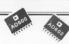
Analog Devices' AD600 and AD602 are monolithic dual-channel, low-noise variable gain amplifiers that provide wide bandwidth and low distortion for use in automatic gain control and programmed gain applications. Each channel of the amp uses a patented variable attenuator and high-speed fixed-gain amplifier. Instantaneous signal-to-noise ratio for a 1V rms output at 1MHz is 76dB for the ADG600 and 86dB for the AD602. Both are available in either a 16-pin plastic DIP or SOIC and are guaranteed for operation over the commercial temperature range of 0° to + 70°C.
Prices for either amp begin at $15 in quantities of 100. Contact Analog De vices Inc., 181 Ballardville St., Wilmington, MA 01887, (617) 937-1428, FAX (617) 821-4273.
Amateur will appear in the 1990 expanded edition, which will be the first hardbound edition. A revised hardbound accumulation covering the period 1963 1989 is being prepared and should be available in 1993.
For information on the index, contact Norman Lathrop Enterprises, PO Box 198, Wooster, OH 44691-0198.
Leads Metal Products introduces the DIN (45mm x 45mm) and %, DIN (45mm x 22.5mm) Chassis Punches.
Manufactured of hardened steel, they are designed for easy removal of the slug after punching. Operable by hand or by a hydraulic knock-out driver, the punch can handle thicknesses up to 14 gauge.
Replacement and resharpening parts are available from Leads Metal Products, Circle City Industrial Complex, 1125 Brookside Ave., Suite C, Indianapolis, IN 46202-2748, (317) 631-7200, FAX (317) 631- 7237.
MCG Electronics offers a range of electronic surge protectors for every data, signal, or telephone line application.
Using the free 16-page catalog and application guide, you can select which protector will work best for your RS 232s, 242s, 485s, 4-20MA loops, modems, FAXes, or LANs.
Contact MCG Electronics, Inc., 12 Burt Dr., Deer Park, NY 11729, (800) 851-1508, (516) 586-5125, FAX (516) 586-5120.
---------
NAD delivers the Monitor Series 2400THX power amp, the first to be approved by Lucasfilm Ltd. for Home-THX theater systems. Its 100W/channel stereo power amp takes advantage of a Power Envelope concept, which offers headroom (IHF at 8-ohm) in excess of 300% its rated power (370W) for transients of a quarter-second duration and longer.
This allows for special effects in music as well as in cinema sound tracks, capable of achieving a peak current as great as 50A, which can maintain precise control of loudspeaker motion even under transitory very-low-impedance load conditions. The NAD amp's THX inputs pass unfiltered signals with bandwidth exceeding 3Hz to 100kHz. The THX weighs almost 27 lbs., measures 17 x 53 x 15”, and costs $599.
Contact Lenbrook Industries Ltd., 633 Granite Ct., Pickering, Ontario L1W 3K1, Canada.
Mackie Designs' Mixer-Mixer combiner lets three smaller mixers be used as one larger one with one loss of inputs, AUX sends, or headphone monitoring. The device is designed for tabletop use or it can be bolted to the inside surface of a rack. With the addition of the Remote Fader, you can control the master out put level of all the mixers plugged into the Mixer-Mixer.
The MixerMixer has a frequency response of 20Hz-40kHz +0dB - 1dB, distortion of 0.025% 20Hz-20kHz, hum and noise of - 94dBu ref. + 4dB operating level 20kHz NBW, a dynamic range of 112dB, and crosstalk of -84dB at 1kHz.
For complete details, contact Ron Koliha at Mackie Designs Inc., 16130 Woodinville-Redmond Rd. NE No. 2, Woodinville, WA 98072, (206) 488- 6843.
AG1375 EasyTech supplies Linear Technology's LT1172 and also has in stock the LT1172CNS8, LT1172CT, and LT1172CK.
The LT1172 is a 1.25A high efficiency 100kHz switching regulator with an in put range of 3V-60V, and draws a low 6mA quiescent current. It can deliver load power up to 20W without external power devices and provides excellent AC and DC load and line regulation.
Applications include offline converter up to 50W logic supply 5V @2.5A, 5V logic to 15V op amp supply and a driver for high current supplies.
A 1991 catalog is also available. Contact Easy Tech, 2917 Bayview Dr., Fremont, CA 94538, (415) 770-2300, FAX (415) 770-2346.
Hafler's latest addition to its Series 9000 is the Model 9130, an amplifier that has rugged double-sided, through-plated, glass-epoxy circuit boards that provide durability, serviceability, and direct signal routing with jumper-less layout.
Other features include a 65W/channel power rating that is bridgeable to 150W into 82, gold-plated RCA inputs, and five way binding posts. Available in both 17” Black Eurostyle or 19” Silver Rack Mount able for $420, it is covered by Hafler’s seven-year warranty.
Contact Hafler, a division of Rockford Corp., 613 S. Rockford Dr., Tempe, AZ 85281, (602) 967-3565, FAX (602) 894-1528.
Contact East's fall 1991 catalog includes test equipment and tools for engineers, managers, technicians, and hobbyists.
Featured are products from brand name manufacturers for testing, repairing, and assembling electronic equipment. Products highlighted are EPROM programmers, power supplies, tool kits, and portable digital scopes.
Also included are DMMs, communication test equipment, soldering/desoldering systems, static protection products, ozone-safe cleaners, magnifiers, inspection equipment workbenches, precision hand tools, tool kits, cases, and more.
To receive a free copy, call (508) 682 2000 or FAX (508) 688-7829 or write to Contact East, 335 Willow St., No. Andover, MA 01845.
DeoxIT and PreservIT from Caig Laboratories are available in nonflammable, nontoxic, noncorrosive, and ozone-safe wipe applicators.
DeoxIT improves conductivity by dissolving oxides that form on metal connector and contact surfaces, eliminating resistance that impedes electrical performance. DeoxIT and PreservIT contain active ingredients that do not rely on sol vents (freon, alcohol, and others) for performance. Both have excellent migration properties that coat and condition the metal surfaces and protect them from oxidation and contamination. On moving connectors and contacts, DeoxIT and PreservIT recoat the moving metal surfaces, providing continued protection and reduced wear and abrasion. Each comes with 50 wipes in pocket-size containers: DeoxIT (part number K-R50W), PreservIT (part number K-B50W).
Contact Mark K. Lohkemper, Caig Laboratories, Inc., 16744 W. Bernardo Dr., Rancho Bernardo, CA 92127, (619) 451-1799, FAX (619) 451-2799.
Circuit Search has announced Version 1.09 of their database of references to articles containing practical electronic circuit designs. This dBase III/III+ compatible database references nearly 13,000 articles and papers from more than 300 technical and scientific journals and magazines. As an interdisciplinary reference source, it can locate circuits by key words from journals in fields as varied as electronics, astronomy, agriculture, physics, chemistry, nuclear science, education, biomedicine, and many more disciplines where electronics can be applied.
The database is installed on a hard disk on an IBM PC or compatible, and used with either its own menu-driven front end or a dBase-compatible database management program. You can locate references by title, circuit description, device type used, author, author affiliation, journal, date, and more. The database occupies about 7Mb and comes on a series of disks.
Circuit Search sells for $375 ( US dollars), including one free semi-annual up date/revision. Further updates cost $40 for one or $65 for two. A sample disk including 400 references, pricing, and additional information is available for $7.
Contact
Peter Sawatzky, Circuit Search, PO Box 268, Breslau, Ontario, Canada, NOB 1MO, (519) 241-1252, FAX (519) 742-4594.
The Mod Squad releases its first power amp, the McCormack Distributed Node Amplifier, or DNA-1 Power Drive. It is a solid-state stereo amplifier that can deliver 150W/channel at clipping into 8-ohm, 300W into 4-ohm, and 500W into 29. Individual local current reservoirs at each output device give the DNA-1 an instantaneous response time as it speeds cur rent delivery to the output transistors.
The drives provide both barrier strips and binding posts for maximum flexibility in output connections. Two units can be returned to the factory for con version into a bridged pair for mono operation in either the balanced or un balanced mode.
Contact
The Mod Squad Inc., 542 No. Hwy. 101, Leucadia, CA 92024, (619) 436-7666, FAX (619) 436-0107.
Analog Devices' OP-497, a high-precision quad operational amplifier, is suitable for designs that require multiple precision amplifiers with low power consumption. Specifications include 50pV maximum offset voltage at 25°C, with offset drift of 0.5uV/°C; 100pA maximum bias current at 25°C, rising to 450pA at 125°C; 2kV/mV minimum open-loop gain, and 625pA maximum supply current per channel. Applications include instrumentation amplifiers, photo-diode preamplifiers, and amplifi ers for thermocouples and strain gauges.
For detailed information, contact Arman Nagavi, Analog Devices, Inc., Precision Monolithic Division, 1500 Space Park Dr., Santa Clara, CA 95052, (408) 727-9222.
Letters
LP NOT CD IN TAA 4/91
Andrea Clark's review of “Intermezzo” was erroneously referred to as a CD recording when it was in fact an LP recording. TAA regrets any con fusion this may have caused.
TOO MANY WARPS I FOUND Andrea Clark's review of “Intermezzo”' (TAA 4/91, p. 62) interesting, as well as producer John Atkinson's response.
I was disappointed in the LP “limited edition.” The first one I received was warped. I returned it to Stereophile. The second one I received was warped and had a bad scratch on it.
I returned the second LP to the address given in John Atkinson's response to Andrea Clark, asking for a refund if they could not send me one without warp or scratches. The third one I received was not scratched but had the same warp as the first two. After spending $24.95 for the LP, plus about $10 in shipping costs, I simply gave up.
I was also only able to enjoy the final cut. It probably is no coincidence that it was on the inside, away from the warp, and that it was a delicate piece without loud transients. Maybe John Atkinson would send me a copy of the new, lower priced, second pressing, if it's not warped?
LARRY GLENN, Eau Claire, WI 54701
RESERVATIONS ACCEPTED GENERALLY, my Saturday afternoons are spent in the pleasurable pursuit of pre paring the weekly gourmet meal, for my husband, a few friends and myself.
The eagerly awaited arrival of the latest issue of TAA contained a review of Stereophile's compact disc (CD) containing the piano works of Brahms. This review was inept and incompetent, raising my blood pressure and nearly causing me to cease my culinary activities.
I am unable to argue the merits of the recording, since I have yet to hear it played. The general tone of Ms. Clark's appraisal is what upsets me.
It shows someone with preconditioned reflexes and prejudices: 'I hate CDs, and I am not going to like this one.”' I particularly take issue with her curt and summary dismissal of CDs. She confesses to having no extensive experience of the medium and indicates no desire to learn. My experience with CDs covers more than six years.
For the very first time, if the engineering is done properly, we are able to hear what the balance engineer heard at the time the recording was mastered.
My morning was pleasantly spent listening to a CD reissue of the marvelous Benjamin Britten Opera “Peter Grimes” originally recorded in analog in 1978 with the conductor Colin Davis and Jon Vickers. The opportunity to hear it in its pristine fidelity, uncluttered by wow, clicks, and the efforts of crystal ized carbon struggling to follow a groove, is sheer delight.
Did it not occur to Ms. Clark that the fault she complained of could well be her own system? Playing a high fidelity piano recording near another piano is really asking for trouble, and subsequent coloration will result, due to sympathetic resonance. Also, might I lay the fault at her choice of speakers-hardly in the front rank for fidelity.
At the end of the day it is the recording's content that matters and amongst Ms. Clark's prejudices is an inability to be objective about the music. My sympathies are entirely with John Atkinson, whose riposte, I thought, remarkably restrained. But then, that's the English for you.
MARJORIE WILLIAMSON; Staffordshire, England
Andrea Clark replies:
With any review, criticism is both expected and acceptable, however, seeing that you have yet to hear the recording, I am to conclude that the arrival of your letter was largely due to my closing re marks on compact discs.
The review is in front of me, and I am straining to locate where I show these preconditioned reflexes you accuse me of having. I am particularly interested in where you see me confess to having no extensive experience with CDs. Allow me to quote myself, 'In my listening experience. . .I have found them to be completely artificial, unnatural, . . . “'etc. It is obvious you did not read my review carefully and have chosen to see what is not there. Let me simplify the matter.
Working in a store with an inventory that was 95% CDs, I have listened to many compact discs. Listening to them at audio stores, audio shows, friends' homes, and everywhere in between. It is difficult not to hear them when everywhere I turn they are being forced upon me. Time and time again, I hope for positive results but they are clearly absent. Many players have been attached to my system. I have spent years researching, listening, comparing, and never has a CD ever approached what I considered to be “pristine fidelity,”' which of course, is a properly cared-for vinyl record, played on a correctly set up turntable system. Your graphic depiction of vinyl and turntables suggests you may never have had one set properly.
Unfortunately, most people fall into this category and it is no wonder they are captivated when first exposed to com pact discs.
You are absolutely correct about the piano being a potential problem-maker.
I am well aware of reverberation problems and have done everything possible to minimize the hazards. The lid is down at all times and the strings are heavily damped. Of all the educated, experienced listeners who have sat in that room, no one has ever complained, or even noticed, the piano interfering with a performance.
Your disapproval of my choice of speakers doesn't surprise me. Most people disapprove until they have heard them on my particular set-up.
In reviewing the Brahms work, I readily admit that I was in no position to comment on the artistry of the performance, or the material, simply because I was totally unfamiliar with the work itself. My opinion that it was “not terribly involving' was just that-an opinion. It was because of my unfamiliarity that I concentrated more on the sonic and technical aspects. After all, I believe that is what I am most qualified to do.
PROGRESSIVE LISTENING
ENJOYED READING your review of Stereophile's “Intermezzo” record and CD.
Your description of the sonic qualities of these samples reminds me of the distortion I once heard on my equipment here. Because of these qualities, which contrasted with the sonic purity heard at high-end stereo shows, the question became, 'What's wrong, and what can be done about it?” Enter The Audio Amateur. There is enough science and practice reported in the pages of TAA to get the absolute sonic best out of most any hi-fi system.
Chronicled in TAA are the efforts of many inquisitive people, who have devised and tested all manner of electronic improvements, which they share for no particular benefit to themselves.
As an experimenter, and reader and occasional contributor to TAA, I can testify that the sonic success of your electronic chain can be easily raised to stellar level, using knowledge found in this magazine. Because of the practical nature of this information, it rarely appears in an academic setting-nor in pricey electronics reference literature.
Granted, not everyone has the inclination to perform surgery on something so relatively complex, unfamiliar and ex pensive as a piece of electronic componentry. My own efforts are still ac companied by a certain thrill and sense of exploring the unknown (in spite of well-laid plans). No problem has gone unsolved or required outside repairs- just measurements and an occasional ex pert opinion.
The skills required to improve our electronics are not so difficult. Anyone can learn to make reliable solder joints and to recognize the hardware, and correlate it with schematic representations, per haps with a little help from friends. The power afforded the mastery of these skills is both formidable and very satisfying.
I am confident that your stereo system will be sounding better in the future, and I trust that your expanding knowledge of “what's wrong and what to do about it”' will play a large role in the transformation. To reiterate, POOGE = “Progressive Optimization of Generic Electronics,” with emphasis on progressive.
DARCY STAGGS; Orange, CA 92669
Andrea Clark replies:
Thank you for your letter. I appreciate your comments and suggestions, but I am afraid they do not apply to me.
First, may I explain there is nothing particularly “wrong” with the sound of my system. It could use some more detail and immediacy, but there is nothing “wrong.” A quick demonstration with what I consider to be reference quality material would soon disprove your assumption.
The distortion I spoke of in the review
was not a result of so-called “in-capabilities” within my system. I have several sonic treasures that are far more demanding than that of Stereophile's “Intermezzo,” and isn't it ironic that this same '“'incapable” system handles these masterpieces with effortless ease.
I am not in the business of doing modifications, nor do I intend to modify my electronics. Fiddling around with a work of art such as the Luminescence preamp is not how I pass my time. I have spent the better part of ten years assembling my system, to its present level, and feel that I have for the most part, achieved my goal, I see no need at all to “mess” with a good thing. I am well aware of the sonic improvements one can make by changing certain caps and resistors, however, this is not an area I plan to explore or experiment with.
I am a listener, not a tweaker. All to often, I have heard the results of component modifications, both good and bad, and have come to the conclusion that if I am truly satisfied with the performance as is, then it is best to leave well enough alone.
BALANCED CIRCUITRY
THANKS FOR ERNO BORBELY’S wonderful article on balanced amplifiers (TAA 1/91, p. 14). I've been a fan of balanced circuitry for a long time.
In addition to phono cartridges being inherently balanced devices, I'd like to point out that analog tape heads and 3000 twin leads are also inherently balanced. Thus, all three traditional analog sources (phono, tape, and tuner) are balanced. In regards to phono preamps, Walter Jung shows balanced circuits in his book on audio op amps (Audio IC Op-Amp Applications, Sams, #21161).
Concerning converting from single ended to balanced and back again, trans formers have an advantage over op amps in that the former block RFI, since their bandwidth is usually 100kHz or less. A hidden disadvantage of op amps is the added power supply needed to run them.
I would also guess that each pair of op amps in each differential stage must be matched for gain, just as the resistors must be matched. It's no wonder so few manufacturers have taken on differential amps; the duplication of parts and their matching would be expensive.
Also, about your Fig. 24 (driving a speaker differentially), since all passive crossovers are single-ended, the circuit would work only for active (balanced) crossovers. I think you could design a passive (balanced) crossover, but you would need a dual voice coil driver like the one in Fig. 1. Basically, you create a mirror-image passive crossover and place it in the minus leg of the balanced line. It's important to remember that “balanced” means that each leg sees an equal impedance to ground, thus the '“balance” above ground.
Another point to watch out for in balanced amplifiers is volume control. The problem is the tracking of the ganged pots. Any mistracking will upset the impedance balance of the circuit and seriously degrade the CMRR. Even a slight mistracking will cause the CMRR to plummet. It's best to use a precision stepped attenuator.
I've found a useful book by R.D. Middlebrook called Differential Amplifiers.
It was published in 1963, so it's probably out of print. The book gets down to the nitty gritty of designing a differential amplifier with tubes or transistors.
Many of his list of references offer very interesting circuits such as cascoding, constant current sources, and common mode feedback for improving CMRR. A CMRR of 100dB was apparently common in 1963.

FIGURE 1: A dual voice coil speaker.
Another difficulty with differential amplifiers is that with imbalances present, a common signal on the input will generate not only a common-mode signal on the output, but a differential signal as well. A differential signal applied to this amplifier will produce common-mode and differential signals on the output.
DIRK WRIGHT; Reston, VA 22090
MULTICAP UPGRADE
I AM A VERY satisfied owner of a Music Reference RM-9 power amp, along with John Jackson, 'A Musical Link' (TAA 3/91, p.36). I have not changed any wiring, but I replaced the 0.22uF capacitors, in the signal path, with 0.22/400V multi caps. I am surprised no one has written to you regarding these caps. They pro duce extended response, plenty of air about the high notes and have an exceptional bandpass.
If you own a Curcio preamp, start with the 0.1 cap. I upgraded by stages and noticed a definite improvement.
The break-in period lengthens as the chain of caps extends. Previously, I used 0.47 MIT caps, which produced more extended bass than the 1uF polypropylene caps. The outer foil lead-end is best placed closest to ground. This is opposite to the WonderCaps style and it's un fortunate their labeling is not consistent, but some distribution marking notes the outer foil lead-end.
These multicaps are smoother, more revealing and worth installing. Also, I agree with B. Syzmanski (TAA Letters 3/91, p.46) concerning resistors R125 and R225 “operating on the edge." I have used 2W Corning resistors, mounted with a space above the board. I observe no visible burn-out after four years use.
CARL CHISHOLM Toronto, Ontario, Canada
ALTERNATIVE PROCEDURE I HAVE JUST READ
James Lin's article “Refurbishing Heathkit's IG-72 Sine Wave Generator”' (TAA 3/91, p.24). If no one has yet commented on other ways to install “vernier” tuning, I offer the following procedure. It works adequately, if not elegantly and with this quantized instrument, any frequency within its range can be selected.
What this procedure does is connect a variable 10k resistor, in series, with each end of the frequency control resistors. Connect to the cathode end of the output tube and to the grid end of the os cillator tube.
The principal shortcoming of this method is that the vernier becomes very coarse at the higher frequencies, in order to have sufficient range at the lower frequencies. It has an advantage over a parallel 10M dual pot, in that a disconnecting switch is not required, since when advanced fully clockwise, the pot adds 0 ohm to the existing resistances.
A ganged 10k dual-linear potentiometer is installed to the left of the 10's frequency switch, under the power on-off switch. The hole must be drilled through the panel and the chassis. If you can find a small (4 “) knob to fit the shaft, you will be able to get your fingers between it and the knob on the adjacent control.
Short lugs 1 and 2, on each pot, with a piece of wire. The resistance across the control will decrease as the shaft is turned clockwise.
Unsolder the white lead, that is connected to lug F6, on the range switch (the other end goes to lug F10 on the 10's frequency control.) Note that lug Fé is on the deck closest to the panel and adjacent to the lug to which a 47pF mica capacitor is connected. Pull the free end of this lead through its grommet, cut it to length, and solder to lug 1 (or 2) of the pot next to the panel. Connect lug 3 of this pot to lug F6 of the range control, routing the wire through the same grommet it went through originally.
Unsolder the brown wire connected to lug R6 of the range switch (on the outer deck adjacent to the other end of the 47pF mica capacitor). Connect the free end (cut short) to lug 1 (or 2) of the outer pot. Connect lug 3, of this pot, back through the grommet to lug R6 of the range-control switch. If the addition tends to add some instability to the oscillator, a small capacitor (ca. 22pF) across lugs 1 (or 2) and 3 of the outer pot should cure it.
Finally, I might add that I have re placed the vacuum-tube circuitry of the IG-72 with op amps. This is not a simple project since an entirely new power supply and re-drilling of the chassis is necessary. While retaining all the features of the original circuit (including 10V RMS output even at the highest frequencies) distortion from 20Hz-20kHz is reduced by a factor of 2 to 5-from 0.025% at mid-frequencies in my old IG-72 to about 0.005%. All frequency, range, and attenuator switching is retained as is the meter circuit. I cannot provide step-by-step details, but interested readers can get the circuit and some construction hints by mailing me an SASE.
LAWRENCE WALLCAVE, Santa Rosa, CA 95404
James Lin replies:
Mr. Wallcave has come up with an interesting idea, one that I confess did not occur to me-that is, instead of adding parallel (and unavailable) 10M-OHM pots which would decrease the notch-filter resistance, add series 10k-Ohm 2 pots to each arm of the filter to increase the resistance. There are advantages and disad vantages to what he proposes.
The first advantage is that his modification does provide a variable control, using readily available 10k dual pots.
The second advantage is that the modification takes very little space. This is significant, because the IG-72 has very little room on the front panel for addi tional controls.
However, the modification also has two significant disadvantages, as I see it.
First, with most vernier controls, the control is off in the counterclockwise position and as it is turned on it in creases the frequency a small amount above the reading on the switched con trols. However, because the series pot increases resistance, it is off in the clock wise position and decreases the fre quency below the readings on the switched controls as it is turned counter clockwise. I believe this is counter intuitive human engineering. It just seems easier to read a frequency as “370Hz plus a little bit” than as “380 Hz minus a bit.” Second, as Mr. Wallcave mentions, this control is very coarse at the higher frequency settings. For example, when the tens switch is set at 10, the control varies the frequency between 10 and 9, which is what you want. However, when the tens switch is set at 100, the control varies the frequency between 100 and 50.
If you absolutely must have a con tinuous variable control, then this ap pears to be the only choice, since 10M-OHM dual pots with DPST switches are essen tially nonexistent. The other alterna tive, of course, is to get an IG-18, the solid state successor to the IG-72, which has a variable control engineered into it, and for which there have been numerous modification articles published in TAA.
Mr. Wallcave's modification of the IG-72 to use IC op amps also sounds in teresting, but I would think it easier to implement in an IG-18.
FOUR-WIRE SUGGESTIONS
I AGREE WITH Csaszar Laszlo in his “Audio Aid”' (TAA 2/91, p. 62) that the four wire principle should improve things by greatly reducing the impedance effects of the speaker wire. I have a couple of observations and suggestions to anyone thinking of using this.
First, the gain of the four-wire system is slightly lower than that of the two wire system (Fig. 1). This is not normally a major concern and could be compen sated for with a small resistor change.
Second, if any of the wires become disconnected, due to a speaker fuse blow ing or the dog chewing the speaker wires, the amplifier will not have any feedback.
If this happens, the amplifier output will become very large, possibly damaging the speaker or the amplifier. Putting in diode clamps or resistor clamps (Fig. 2 should protect your equipment without interfering with the circuit's operation; 1N4148s should work for the diodes, and 1k-Ohm resistors should be adequate.
Third, wrapping the feedback around the long speaker loop may interfere with the amplifier's stability and cause oscillation. To reduce the likelihood of this occurring, parallel the resistors/diodes with capacitors (Fig. 3); 0.1uF film type capacitors should be a good choice.
GEORGE ROCHELEAU Tempe, AZ 85281
Csaszar Laszlo replies:
Thanks for your kind response concern ing the four-wire principle in audio.
I agree with your remarks, and I use clamp resistors of 100 ohm in parallel with 0.1uF polystyrene capacitors. This eliminated any spurious oscillation caused by the approximately 40' speaker cable ...

FIGURE 1: Gain of the four-wire system vs. the two-wire system.
FIGURE 2: Adding diode or resistor clamps.
FIGURE 3: Paralleling the resistors/diodes with capacitors.
... (In fact, this length was the main reason I decided to include the speaker cable in the feedback loop.) I understand Kenwood has been using this principle. They apply it between their power amplifiers and the loud speaker and also between their preamps and power amps. I don't know whether ...
----------------
PREVIEW,
SPEAKER BUILDER Issue 2, 1992
75W Two-way satellite speaker system.
Stable satellite swivels
Caps for crossovers
Two-way crossovers
Constructing a bandpass enclosure
Twenty foot dipole ribbon loudspeaker
Review of The Audio Glossary
---------------------
...it is patented or not. My only excuse is I didn't know about this when I wrote my Audio Aid' Second, it has been known in metrology for a long time.
A point must be cleared up now: the quality of the wires does matter. Any wire (be it in the feedback loop or not) has inductance, capacitance, propaga tion delay, dielectric dissipation, radia tion, and so on. My experience showed that you cannot spare good quality cables by any tricky principle.
CAD SHAREWARE
I HAVE BEEN BUYING Speaker Builder and The Audio Amateur for several years.
Both are superb.
I build multi-channel sound equipment for movie theaters as an occupation. During the design process, I use several computer-aided design (CAD) packages. J. M. Didden's article (TAA 2/91, p. 29) recommends the use of smArtwork, OrCAD, and DruckerPlot.
I had been looking for a good and inexpensive CAD program when I found and purchased EasyPC (PC Boards and schematics) from Number One Systems, U.K. You can buy the same package in the USA for $195. from Automation Inc., 7840 Angel Ridge Rd., Athens, OH 45701, (614) 592-1810.
Draft Choice (engineering and general drawing) is a shareware program. This program costs $50 and is available from
Trius Inc., 231 Sutton St., Suite 2D-3, PO Box 249, N. Andover, MA 01845-1639, (508) 794-9377.
Both packages require an IBM PC, XT, AT (or compatible), 512K RAM, Hercules, EGA, CGA and VGA, and printer output to 9 and 24 pin, H-P IIP Laser Printer and Plotter.
I have used smArtwork and OrCAD for several years, but this set of inexpensive software (EasyPC and Draft Choice) is better ($245 compared to $595). [The current price of OrCAD, SDT IV is $595. Call (503) 690-9881.]
There is a lot of excellent software in the shareware market. I think that a re view of these kinds of design tools would be helpful and interesting to your readers. Please continue the fine work you are doing.
Luis A. SANCHEZ MOELLER; Monterrey NL, Mexico
HELP NEEDED
I AM WRITING in the hope that TAA readers will be able to assist me in restoring a family heirloom-a Bell Sound Systems 2200C amplifier. Unfortunately, the output transformer ( Bell #B-20235) was custom manufactured for Bell as it contained a center-tapped cathode “feedback” winding to the pair of 5881s at the output. All my attempts (including speaking with former Bell employees) have failed to locate a replacement. I would greatly appreciate any advice or information.
LES BERNSTEIN, 123 French St. Bristol, CT 06010
OP-AMPS REVISITED
DUE TO THE RAPID pace of IC op amp development, the application of the TL070 as a phono stage amplifier is sonically obsolete. My DH-110 now uses any of the superior op amps listed below. These op amps are interchangeable, and so can be easily compared. Included is a schematic of the revised portion of the circuit in Fig.
1(TAA 4/91, p. 45) with updated pinouts and the LM334Z pulldown.
For a source of up-to-date PC boards ...

FIGURE 1: The revised portion of the circuit in question, with updated pin outs and the LM 334 Z pulldown.
... useful in this application, refer to the advertisement in TAA 4/91, p. 39.
For U1: OPA 627 BP Burr-Brown Precision High-Speed Op Amp LT 1115 CN8 Linear Technology Audio Op Amp Analog Devices Monolithic Op Amp AD 847 IN
Also:
LM 334 Z National Semiconductor Current Source Linear Technology Current Buffer IC LT 1010 CT DARCY E. STAGGS Orange, CA 92669
SOURCES
Linear Technology 1630 McCarthy Blvd. Milpitas, CA 95035-7487 (800) 637-5545 Analog Devices, Inc.
70 Shawmut Rd. Canton, MA 02021 (617) 329-4700 Burr-Brown Corp PO Box 11400 Tuscon, AZ 85734 (800) 548-6132
National Semiconductor, PO Box 58090 Santa Clara, CA 95052-8090 (408) 721-5000
J+FET SEARCH
I HAVE READ and reread William Chater's “Mostly MOS Preamp” article (TAA 1/90, p. 8; 2/90, p. 26) with much enthusiasm. My compliments on what seems to be an excellent design and the detailed and readable essay accompanying it. In collecting the components used in the design, however, I have come across a problem.
The J270 p-channel JFET used in several places in the preamp is no longer available from Newark Electronics, the source mentioned in your article. In deed, Harris Semiconductor ( Newark's supplier) is no longer producing that de vice-nor any other JFET. They inform me that other companies (I believe Siliconix was mentioned in the conversation) are also dropping JFETs from their product line. I hope this trend does not continue.
I have not been able to find another supplier for the J-270. Do you have any suggestions? Also, I do not have the per tinent data for the device to determine a suitable substitute (the usual cross references do not list it).
But perhaps this is not so tragic as I initially thought, as I have found a vendor for the devices that you originally considered for the unit, but rejected be cause of availability, the 2SK147 and 2SJ72. The supplier is MCM Electronics ( 650 Congress Park Dr., Centerville, OH 45459-4072, (800) 543-4330, FAX (513) 434-6959). They advertise widely and cater to hobbyist types. They have numerous other hard-to-find items and should be on everyone's supplier list.
Unfortunately, I do not have the data sheets for these devices either. What were the selection criteria that the Toshiba devices satisfied, and how would your circuitry need to be changed to use them? This may become clear to me when (if ever) the documentation Toshiba promised me arrives, but I would appreciate your insight in the interim.
GLENN A. PLUNKETT, Cincinnati, OH 45245
William Chater replies:
Mr. Plunkett has indeed uncovered a discouraging trend in the transistor market. I have checked with my local Los Angeles area Newark supplier, and they confirm that the J270 is being discontinued. Further, the 2N5114-6 series I mentioned in the article as a possible alternate is also being dropped.
To try to help overcome this lapse in the transistor market, I have made a short survey of recent catalogs to find JFETs you can still purchase for use in the preamp. The preamp calls for three different JFETs: the 2SK147, the NTE458, and the 270.
The Toshiba 2SK147 and the NTE458 are still available in several places. Consolidated Electronics ( 705 Watervliet Ave., Dayton, OH 45420) stocks not only the 28K 147, but its p-channel dual, the 25]72 (not used in the preamp). For a long time these units were hard to obtain.
Further, a call to Toshiba has revealed a near equal to these units, with some what reduced gain, that can work well in the preamplifier circuits. These are the 2S8K170 and its dual the 2S]74. They are also available from Consolidated and are somewhat less expensive as well.
The 28K170 would work properly in the RIAA stage where the preamp calls for the 147. The latest catalogs also show that MCM Electronics, mentioned by Mr. Plunkett, sells the 2S]72 and the 2SK170, but not the other two. (Note that the MCM transistors are not a dual pair, but are one from each gain type.) The NTE458 and up to now all the other NTE catalog units are still avail able in most retail outlets. (See also the equivalent Philips ECG line.) The p-channel J270 (or its higher Ig version, [271) is thus the main problem in parts gathering. The NTE series has some p-channel units: the NTE460 or the NTE326 show an Ips of at least 2mA with gm of around 3,000 umbhos.
These units still fall short of matching the NTE458, but can be used in those places where it is a cascode for another transistor, as long as the measured Ig is at least as much as the circuit bias cur rent. For example, the NTE460 could be used as Q184, 203, or 303 if you check that the 460 has enough Ig.
This still leaves us without p-channel units for Q183 and 201-202 (or 301-02). In those spots, we need to have a good match with the n-channel units Q182 and 204-205 (or 304-305). Probably the best thing to do is use the Toshiba 28]74/28K 170 pair. I think I would have done this in the original design if these units had been readily available.
This Toshiba pair (the J74 and K170) will have a somewhat larger bias current point in circuit MOSPA1-1 (the RIAA post-amplifier) than the NTE458-]270, but will still operate the circuit at a satisfactory current level. (About 5mA was the design level of current in Q185 186; this would rise to around 8mA with Q182-183 changed to the Toshibas.) In the line driver and tape driver circuits, a similar substitution of transistors for Q201-204 (301-304) would raise the bias current levels somewhat.
This change would be adjusted for by the servo control from points a,b (x,y). You might have to reset R242 (R355) if the voltage control points in the servo loop run into their limits in making this correction. Otherwise, the substitution should perform as well as, or maybe better than, the original parts.
In making device substitutions, there is always the possibility some unfortunate high-frequency changes may oc cur. An oscillation might even result, so I hope you test any changes you make (as suggested in part two of the article) before you commit to the new parts.
MORE ON MOVs
I HAVE YET another idea to add to the continuing discussion of MOV protection in Letters (TAA 3/91, p. 49). A previous suggestion was to use fuses to isolate the MOV bank in the event that they short circuit. However, I like to leave my system power on, and failure of the MOVs in the suggested fused circuit would leave the system unprotected in the event of such failure.
I propose a circuit shown in Fig. 1.
I use the previously proposed fuse arrangement. However, I use a power relay to provide switched AC to my system, since my whole system draws current through this arrangement. It is much cheaper to find a surplus 20A or more relay than it is to find a toggle switch.
Since the coil of this relay is operated from the MOV protection circuit, sys tem power is shut down in the event of fuses F1 or F2 blowing. In addition, fuses F1 and F2 can be optimized for the MOV circuit/relay coil combination while the 20A fuse can provide power to the re mainder of the system.
SW1 can then be a cheaper low cur rent device to switch an entire system ...

FIGURE 1: A proposed circuit in the MOV discussion from John Hanley.
... on and off. Further, SW1 isolates the MOV bank from transients when the system is not powered, thus keeping them out of unnecessary danger when their protection is not required. (Further, the MOV bank can snuff any high voltage transients from the relay coil when SW1 is turned off.) Since it is hardly more expensive to find a double-pole relay as a single pole of RL1 to provide DC to sequencing circuitry and/or solid state relays, as has been shown in several articles in TAA.
Alternatively, the second pole can be paralleled with the first pole to provide a higher AC current rating if multiple power amp, etc., draw power from this arrangement.
JOHN HANLEY, Burke, VA 22015
BANANA PLUG TIP
JAMES LIN'S AUDIO AID in TAA 2/91 (p. 61) about a jig for testing cable capacitance is a useful idea. Going one step further, his four bits and pieces can be simplified by using a single standard 3.5“ spacing dual banana plug, with an integral phono jack.
Most test equipment that uses two banana jacks have a standard 0.75” spacing between them. Several manufacturers ( Pomona, HH Smith) supply stackable dual banana plugs with the same standard spacing. In the area between the two plugs there is enough space to mount a phono jack which can be connected to the two plugs. Mounting the phono jack at right angles doves not interfere with the stackability. Check the Pomona MDP-0 or the HH Smith 1677-103.
I have made up several of these and find them convenient when connecting various items of test equipment.
FOREIGN READERS
Due to the limitations of our Fast Reply program, we are unable to process requests for information from our foreign subscribers.
HOWEVER, our advertisers would certainly like to hear from you directly via mail, phone, or FAX. Please don't hesitate to contact them for the products/information you are interested in.
I'm a new reader, and I'm baffled by some of your jargon. What's a POOGE!? I understand it's an acronym for a group of improvements, but what are they?
[Progressive optimization of generic equipment. -Ed.]
MARK WEBER, Toronto, Ontario, Canada M4T 1V2
COMPUTER VIRUS MICHELANGELO
WE ARE WRITING at this time as a service to our customers and supporters because be recently discovered a software virus on our computer system. The virus we encountered is apparently widespread, and we would like you to be sure it has not contaminated your computer system from any source. Although it is unlikely we have passed this virus on to you, the virus threat is real and it is important that your take steps to keep your system virus-free.
While our computer system and any software loaded into it is constantly monitored by anti-virus software, this particular strain known as Michelangelo went undetected until last week. This virus sits in the boot sector of your floppy or hard disk and does nothing until March 6th. Then it begins to write random characters to your disk. It's sad to know there are people in the world who spend their time writing such destructive garbage.
This virus enters your system when an infected diskette is in a disk drive on bootup regardless of whether it is boot able or not. It should not enter your system if your simply read from or write to the infected disk. However, once it is on your hard disk, it can copy itself onto a diskette accessed in any drive and therefore can be spread around quickly.
We highly recommend anti-virus soft ware be installed on your system, Until now we thought viruses were somebody elses problem and would never affect us.
Although we keep our computer isolated to keep it immune, we were sadly surprised.
The Michelangelo virus and hundreds of others can be detected with readily available software from Norton, Central Point Software and other companies.
McAfee Associates provides virus detection and removal software which you can download and us FREE FOR 5 DAYS from their computer bulletin board system (BBS). Please do yourself a favor and scan your system with one of theses pro grams to ve sure it is virus-free! It is equally important of course, to back up all your work regularly.
Since the Michelangelo virus resides on the boot sector of your hard disk, m there is a way to easily get rid of it if you own Microsoft DOS, version 5.0. You can use FDISK with the undocumented option /MBR (for Master Boot Record) to refresh the master boot record thereby writing over the virus and eliminating it. This will work in most cases but it is still important to scan your disk to be sure NO viruses are present. This procedure will not remove the virus from your diskettes, if infected. Please practice SAFE computing.
MICHAEL CHAMNESS
SpeakEasy 46 Cook St. Newton, MA 02158
CAREFUL MODIFYING
Just THOUGHT I'd drop you a line and thank you for the Analog Devices' AD847AN/AD827AN recommendations.
Since we last spoke on the Magnavox 2041 project I have acquired a Philips CD80. In the interest of quick, straight forward improvements I installed a pair of 847s (in sockets for future experimentation) replacing the existing 5534s piece for piece, no other changes or adjustments of any kind. The improvement is tremendous! For less than $20 I trans formed the CD80 into a sonically excellent machine. It was already a physically excellent unit, especially for under $600 (discounted). Makes me wonder what reputation this machine might have if Philips used these ICs to start with, despite the cost increase! After impressing an audio friend who owns a Sony DCP-X55ES, he also became interested in the improvements. This required the installation of the 827s to replace the 5532s in his unit. The Sony is such an impressive unit “stock” that one has to wonder how it can be manufactured with those ancient ICs! The improvement here is equally impressive and, in my opinion, sonically surpasses the Philips. One change I could not do to the Sony was update the output coupling capacitors-no schematic, Sony hasn't chosen to furnish them despite my efforts. Does anybody know the part IDs/ locations (electrolytic bypassed with a 62 The Audio Amateur 1/92 small polystyrene)? Philips on the other hand sells schematics directly and they are reasonably priced. The CD80 is direct-coupled though, no caps to improve.
It was interesting to hear the improvements that took place between these two units side by side as the ICs were in stalled and comparisons took place. The Sony was “best” stock, the CD80 sur passed it with 847s, and the Sony pulled out in front again with the 827s. Quite a change for the number of parts required, simplicity, and cost! Thanks again John, and keep up the great research!
GARY MCKENZIE; Amarillo, TX 79109
John Allgaier replies:
Thank you for the feedback concerning the Analog Devices op amps. I have been quite pleased with their sound improvements also. It's always nice to have others corroborate your findings. A newer, lower noise single amplifier recommended to me by Chris Hyde, Analog Devices' Manager of Applications Engineering, is the AD829 (samples on the way). Mr. Hyde can be reached at Analog Devices, 181 Ballardvale St., Wilmington, MA 01887 (800-262-5643) for data sheets, application notes, and advice.
As for your Sony dilemma, manuals are now available from Sony Publications, PO Box 20407, Kansas City, MO 64195 (816-891-7550). Manuals are $9 plus $1.35 shipping and handling plus any state or local taxes that apply. Terms are prepay by personal check, money order, or Visa/MC. The CDP-X55ES manual is in stock.
Since this player uses the NE5532 dual op amps, in order to eliminate the out put coupling capacitor, the piggyback #4 board (TAA 1/91) offered by Old Colony will work nicely. Getting rid of this capacitor and any series resistors is another worthwhile sonic improvement. With the Philips CD80, I recommend implementing the changes spelled out in my article “Improving the CDB-650's DAC” (TAA 1/91, p. 10).
Good luck with your endeavors and don't be afraid of careful modifying.
60W MOSFET
CAN SOMEONE HELP me with some problems I am having with the Borbely 60W MOSFET power amplifier (TAA 2/82, p. 7)?
I bought the amp as a kit during an Old Colony sale. My problems are:
(1) When I supply power to either board of the amp, in about eight sec onds, R6 and R17 start to smoke. I have checked and rechecked my wiring hook ups and they are fine. My power supply is almost the same as Mr. Borbely's. I am using one toroidal transformer per channel and each one has two second aries of 18V AC.
I have wired the transformers in series for 36V AC, which is about 45V DC. I have paralleled 10-2200uF caps, per channel and fused each rail. Voltage measured after the fuses is about 53V DC, no-load, for each channel. After I removed R17, I measured 34V across the circuit board holes, so I placed 682 AW resistors for R6 and R17. In about 12 seconds these also started to smoke.
On page 9 of Borbely's amp article, he gives an example where a value of 200Q is used for setting the bias for the driver transistors. So I inserted a 2000 “UW resistor for R6 and R17, in both boards, which seems to work fine-or does it? (2) I cannot set the bias in the output stage. After I adjust the pot, counter clockwise, and measure the current, at the empty-fuse holder, it reads 125mA.
When I make a minor adjustment, to the pot, the current suddenly jumps up to about 275mA and steps up from there.
My readings are 275-276-277-278 and on and on. My meter only reads up to 325mA and the next scale is too high to read anything that small. The meter is digital. Even though the bias current is high the MOSFETs became only slightly warm for the five minutes I tried to set the current.
The pot's ohm-value setting, from low to high, is 0.2 ohm to about 450 ohm. I left the pot on one of the amps, fully clockwise, and pop went C9, the 22uF 63V cap.
I'm sure my wiring is fine and my ground is coming from the two wires that I connected in series on the trans former. Which is connected to the filter caps and then to the ground on each board of the amp. I can't figure out what's wrong. Any help you can give would be very welcomed.
FREDDIE BOUEE JR.
Las Vegas, NV 89101
Erno Borbely replies:
1. Assuming that the power supply is wired properly (i.e., + 40-50V) I would suggest carrying out the following measurements on the amplifier. To be able to do this, one needs a Variac, to apply approximately 10V DC to the board.
a. D1 is a 1-2V REF diode, there fore the voltage drop across R10 ( =300 ohm) should be 0.6V. This determines the input stage current to 2mA (1mA each for Q1 and Q2.
b. If this is correct, check the same, on the negative side: D2 = 1.2V, voltage across R12 = 0.6V, i.e., input current is 2mA.
c. Check the voltage drop across R5. It should be 2.2V; the same across R6. If more than this, input stage does not work properly.
d. Do the same across R16 and R17.
If the input stage works OK, i.e., the voltage across R6 and R17 has to be close to 2.2V. This means = 33mA in Q8 and Q10. This should not burn up the resistors.
2. When above is OK, check output DC voltage: it should be close to 0-V DC.
(A few mV offset is OK).
3. If the input stage and second stage is correct, see 1, then setting the bias should be easy, as described in my article.
Although I am not sure, somehow I feel that the supply might not be wired correctly. You state that you use two transformers, one per channel, each having 2 x 18V AC sec. This makes only + 25V, a bit low for this amplifier (it is 50V total if you measure it between the two supplies). I see a possibility of using the two secondaries in series, but grounding one side instead of the CT, means you run an amp which is supposed to run off + supply, with a single-ended supply.
Just a thought.
Your problem is difficult to diagnose without measuring it, but I recommend starting with the input stage as described above.
Hope you can manage to make it work.
Good Luck.
BURR-BROWN DUAL OP AMP I RECENTLY RECEIVED a data sheet from Burr-Brown on the OPA2604 dual operational amplifier. It has several interesting features that would make it a viable upgrade from other dual op amps such as the Signetics NE5532 or Motorola MC34082. Among these features are:
FET inputs, low distortion (0.0003% at 1kHz), low voltage noise (10nV/square root Hz), high slew rate (25V/us), wide gain-bandwidth (20mHz), unity-gain stability, wide supply range (4.5 to 24V), and the ability to drive 600 ohm loads.
Except for the two high speed npn transistors that comprise the actual output stage, the OPA2604 uses field effect transistors (FET) in the signal path, including the input stage, input-stage load, and the phase-splitting section of the output stage. The junction field effect transistor (JFET) input stage holds input bias current to approximately 100pA.
This dramatically reduces noise with high-impedance circuitry. The two channels of the OPA2604 are completely independent, including all bias circuitry.
This prevents crosstalk through shared circuits other than the power supply.
The Burr-Brown data sheet implies that the distortion produced by the OPA2604 consists primarily of even or der products that are much easier on the ear than the odd order distortions which bipolar transistor circuits tend to pro duce. This quality is shared with vacuum tube amplifiers and accounts in part for their continued popularity among audiophiles.
I obtained a pair of these devices and used them in the output stages of my modified Magnavox CDB473 CD player.
Previously, I had replaced the stock LM833 devices with MC34082s. Also, I built a separate power supply for the output stages using a toroidal power transformer, bridge rectifier, and 723 regulators with MJ2955 and 2N3055 series pass transistors. The power supply modifications eliminated noise picked up from the laser servos, and the Motorola op amps were much smoother sounding than the LM833s.
The new Burr-Brown op amps have several advantages over the Motorola MC34082's: lower noise, lower distor tion, wider bandwidth, higher-current output stages, and better isolation be tween the two amplifiers in the chip.
After installing the OPA2604s, I noticed improved resolution of detail. The soundstage became wider, deeper and images became more sharply delineated.
The quality of the bass improved notice ably. Midrange details, previously missed, became audible, and high frequencies had a smooth non-irritating character. Summarizing I would say that the OPA2604 is a worthwhile upgrade, which many Audio Amateur readers should be able to install easily.
ROGER JOHNSON Edmond, OK 73013
NOISE FILTERS RECENT ARTICLES by L. B. Dalzell (“About Noise,” TAA 2/91, p. 10) and Gary Galo ('Ask TAA,” TAA 2/91, p. 46) reported the benefits of filters to remove EMI and RFI from the power feed to their stereo systems. Earlier equipment reviews in Stereophile also de scribed the benefits of power line conditioning as well as the use of ferrite chokes (TDK Digital Noise Absorbers) on power, interconnect, and speaker wiring.
My experience with these devices has not been at all positive. I would advise that TAA readers listen carefully to their own systems before accepting that there is a need for EMI/RFI filtration.
In my system, when the Digital Noise Absorbers were added to the interconnects they killed the crispness that gives life and air to transients. They also muffled the dynamics of the best recordings.
Moving them to the speaker cables generated an unpleasant distortion that al most sounded like an overloaded amplifier. When used on the power cord to the CD player they again muffled dynamics.
A commercial multistage power line filter made by Sprague did the same.
Using a large ferrite clamp on filters from Radio Shack on the power amp AC cord caused distortion on loud transients.
Because the results of these tests were all pointing away from adding inductive filtering to the power supply, I decided to try to reduce the resistive and inductive impedance of the AC supply to my system. I ran a dedicated power circuit directly from the main circuit breaker box to the stereo. I used a dedicated 30A breaker and 10/3 copper wire. By shop ping around I was able to find a receptacle that would terminate #10 wire and used all-brass conductors. A plastic box and cover plate was used to mount the receptacle.
The improvement in the sound of the stereo system was very worthwhile. In creased dynamics, better defined bass and more extended highs were observed.
I decided that if some were good, more would be better, and so I ran a second dedicated line, this time from the other hot bus in the breaker box. Putting the power amp on one power line and the CD player on the other gave a slight additional improvement in clarity and dynamics. The wire and breakers for both circuits cost me less than $100. It is easily the best money I have spent on system improvement recently.
These observations may conflict with those of your authors but it is what I hear When you write for HELP!!!
1. Please enclose a self-addressed stamped envelope (SASE).
2. Leave room for replies on your sheet of questions.
3. Don't ask for authors' addresses. They like their privacy too. We will forward your letter if, and only if it contains a reply envelope. If the author lives abroad, enclose an addressed unstamped air-mail envelope and one international postal reply coupon, available at your post office.
4. Please resist the temptation to use us as design consultants, research assistants, product index clerks, project trouble shooters or equipment evaluators. Doing so slows up our editing.
5. If you have a problem with one of our circuits, fully describe the problem and what you have done about it. Include all significant voltage and/or current readings, and don't forget that SASE! on my system. The CD player is a Magnavox 582 with modified power supply, NE-5535 I/V converters and EL2003 video output buffers DC-coupled to the output.
Interconnects are Neglex 2534. Power amp is a Carver M400t with regulated power supply to the driver circuitry, NE-5535 input IC, and 80,000uF of additional filter capacity on the output stage power supply. Speaker cables are each 28 conductors of #24 individually insulated wire (telephone trunk cable). I live in a suburban area with some retail business and light industry within a mile of my house.
I would be interested in any suggestions as to why my system appears to respond differently than the authors'.
JOHN BUSCHMANN; Knoxville, TN 37950
L. B. Dalzell replies:
Your letter to TAA was forwarded to me for comment. I found it most interesting, but it also brings forth a few mysteries. I cannot find any “Digital Noise Absorbers' in my files, nor do I know what you mean by the “ferrite clamp,” and the amp modifications puzzle me.
The Carver M400t, as I recall, was a modified unit after Bob Carver under took his “transfer function” modifications while visiting Stereophile. His objective was to make his units sound just like a most expensive amplifier that Stereophile liked, hence the “t”' suffix.
I obtained a schematic showing the modified circuit, and found there was a capacitor now in the feedback network marked “polypropylene polyester.” The drawing is dated 1983.
If one looks up the filter formulas, and then calculates the roll-off of the commercial RFI units, it will be found that the filters begin cut-off about 70-100kHz.
This allows them to pass the 60Hz line as though they were not there. At high frequencies, where voltage spikes and noise can be a problem, they will attenuate the undesirable affects on the line. Any such filter added to the AC should not affect the audio output under normal line conditions. However if the line is normally noisy the effects can be immediately noticed. This brings up a problem; is the line noisy, or did the filter have an unnecessary effect? You say that you have added capacitors in your M400t. The amp has really got three power bridges and three different voltages and three sets of output transistors. The higher voltages and the drivers are to come into play only when the basic 20W amp runs out of steam, then they switch in and help. Where did you place the 80,000uF!? The original design of the M400t used a “BI-FET” op amp for the input, while you have evidently replaced it with a bi polar. A FET input op amp would have higher input impedance, and the Carver manual indicates a reason for the FET unit.
Now “line conditioners” can be a different item. Voltage regulators compensate for differing line voltages, however they must not add distortion to the power sine wave! Your new dedicated AC power supply is a great idea. I did much the same thing.
Any device that adds a low frequency impedance in series with the AC power could cause problems, especially with the amplifier you are using. May I suggest some correspondence with Carver regarding the modifications you have made. And in all sincerity, I would suggest an upgrade of the amplifier to something more modern.
After the first chapter of this reply, I searched around and found that one of the fellows in a great audio shop had heard of the “Digital Noise Absorbers” and he found a mail order catalog illustrating the devices from TDK. I have ordered a pair for test, but in the mean time I drilled and sawed a large chunk of ferrite material I had on hand, and tried the pair I made. While the ferrite material may differ, my results are negative thus far. On the AC line one didn't do much of a job, for as far as I can see there was only a bit of attenuation of “common mode” spikes. On interconnects they made no difference that I could detect.
I also found a Carver M400t and borrowed it for trial. Typical of Carver designs, this unit has a complicated power supply. The supply is regulated with the use of a “triac.” It puts out three plus and minus voltages for the six output transistors that are switched in as I have described. To me the transformer seems small when compared to the more usual power supply. The regulation uses a shunted bridge, a rather unusual configuration. Using a low frequency impedance in the power supply, I found that the regulator triac tended to switch on and off quite fast and frequently. Consequently I have sent you a COR-COM filter for you to try in the power line to the amp. Also I see on the drawing that the M400t uses a two-wire cord for power, hence the chassis is not grounded to the protective third wire. However, the design does have three capacitors to filter the input, one across the line, and two from each side of the line to internal ground.
Due to the fast regulator, I would surmise that one must be most careful of any added impedance in the AC power cord, but I found the COR-COM devices had no effect on the regulator or the sound output.
Thank you for the interesting and stimulating letter. I still believe, that like chicken soup, EMI/RFI filtration, 'properly done may not do much, but it sure can't hurt.
Contributing Editor Gary Galo replies:
I'm convinced that there is a need for power-line filtering on every audio system. However, you seem to have interpreted my recommendation for power line conditioning as a blanket endorsement of any device claiming EMI/RFI filtering, including devices which clamp onto your interconnects and/or loud speaker cables.
In fact, I haven't recommended any such devices. I believe that power-line noise must be killed (or minimized) at the source before it is allowed to corrupt your signal path. This means filtering the AC line itself.
Adding the TDK ferrite rings to your speaker cables makes no sense to me at all. Your amplifier is now required to magnetize the cores of the chokes, in addition to delivering power to the loud speaker load. The unpleasant distortion you mention is probably the result of magnetic saturation of the rings. As for the muffled dynamics you report when the Digital Noise Absorbers are used on interconnects and power cords, I suspect that musical transients are being wasted on magnetization of the ferrite rings, rather than being transferred to the other end of the cable. These same comments apply to the Radio Shack clamp-on filters when used on your power cords.
Running dedicated power lines for your audio equipment is worth every dollar spent. Last summer I ran five new 20A lines when I redecorated our living room. Two are used for my low-level equipment. One of these feeds power line filtering which operates my preamp and CD player, while the other is for accessories, including a reel-to-reel tape recorder and a cassette deck. I have a pair of stereo power amps in my biamped setup. Each amplifier has its own dedicated power line and filtering. The fifth line is vacant for now, but it's there if I need it.
I can't comment on the Sprague power line filter you mentioned, since I don't know which one you used. If you are going to use a commercial RFI/EMI filter, be sure it is rated for at least 20A, and don't use a single filter for low-level electronics and your power amp-use two of them.
The best way to keep digital noise out of the rest of your system is to feed your preamp and CD player from separately isolated power outlets. I'm referring to transformer isolation. Audio Power Industries Power Wedge II (TAA 4/91) is a good solution. If you have a separate digital processor, plug it into an isolated outlet.
Finally, try putting Panasonic Interference Suppression Capacitors across the line cords of all of your low-level equipment. I use 0.47uF @ 250V AC. Put one across each power transformer's primary winding, on the transformer side of the line fuse. These are available from Digi Key as part #P4614 (800-344-4539).
Don't use just any 0.47uF capacitor. The Panasonic capacitors are UL approved for 250V AC.
These capacitors help prevent noise generated inside the component from getting out onto the power line, and in to other equipment. Noise generated by the digital circuitry in your CD player is one such example, along with current spikes produced when the rectifier diodes charge the filter capacitors. The latter problem was discussed in a recent is sue of Compliance Engineering. These capacitors are very beneficial, even when other power line conditioning is used, including the Power Wedge II and the Adcom ACE-515.
--------
AD
THE WILLIAMSON AMPLIFIER
D.T.N. Williamson
In April 1947, Williamson's power amplifier, using excellent-quality push/pull output tubes, a special output transformer, and a highly filtered power supply, became an overnight success. The author takes the reader deep into his design considerations, offering practical advice on how to build the units plus concise instructions on setting up the new amp.
A cult classic.
Year 1947, 1990 Pages 40, 0-9624-19184 Softcover 8.25 x 11 $4.95
AUDIO AMATEUR LOUDSPEAKER PROJECTS
Audio Amateur Magazine
A collection of the 25 best speaker articles from Audio Amateur during the decade of the 1970s, proof that great designs are never out-of-date, a rich source of both theory and practice as well as design.
The electrostatic and transmission-line pieces are particularly interesting and useful.
Year 1985, 0-8338-0193-7 Softcover 8.5 x 11 Pages 135, $20.00 This easy-to-read classic, last revised in 1949, introduces the reader to concepts such as impedance, phons and decibels, frequency response, response curves, volume and watts, resonance and vibration, cabinets and baffles, horns, room acoustics, transients, crossovers, negative feedback, Doppler and phase effects, and much more. A provocative survey of the right questions about sound reproduction.
Year 1949, 1990 Pages 88, 0-0624-1913-8 Softcover 5.25 x 8.5 $6.95
KILLER CAR STEREO ON A BUDGET: AN EASY CURE FOR HO-HUM AUTO SOUND
Daniel L. Ferguson Providing quick and tested methods for upgrading your car's sound, this manual provides an excellent, easy-to-understand, hands-on treatment of the cost effective design and installation of high-quality vehicle sound systems. Included are Getting Started;
Sedan, Hatchback, and Pickup Truck Systems; Speaker Cabinet Design; Filter Crossovers; and Installation.
Year1989 Pages 118, 0-9624-19109 Spiralbound 5.25 x 8.5 $9.95
THE LOUDSPEAKER DESIGN COOKBOOK Vance Dickason This new fourth edition of speaker designing's “bible” is twice as big as its predecessors and features brand new chapters on how loudspeakers work and loudspeaker design software. Other chapters cover closed and vented boxes, passive radiators, transmission-line systems, cabinet construction, drivers, crossovers, and loudspeaker testing, plus a complete resources listing. By far, the best-selling book in the field.
Year 1991 09624-19176 Softcover Pages 152
$29.95 HARD-TO-FIND AUDIO BOOKS- AND MORE! ASK TODAY FOR YOUR FREE CATALOG OF KITS, COMPONENTS, CABLE, SOFTWARE AND TEST CDs!
¢MC/VISA WELCOME! OLD COLONY SOUND LAB PO BOX 243, DEPT. A92 PETERBOROUGH, NH 03458 24-HOUR LINES:
TEL (603) 924-6371 FAX (603 924-9467 J. Gordon Holt Authored by the founder of Stereophile magazine, this new best seller is a comprehensive overview of over 1,900 technical and subjective audio terms explained in precise yet at times humorous fashion.
Three editions: Softcover (S); Hardcover with Dust Jacket (H); and Limited, Autographed Hardcover with Gold-Embossed Binding and Dust Jacket (L).
Year 1990 Pages 152
0-9624-1914-1(S) Softcover 5 1/4 x 7.5 $9.95
0-9624-1914-1(H) Hardcover 5.25 x8 $17.95
0-9624-1914-1(L) Limited 5.25 x8 $30.00 BULLOCK ON BOXES
Robert M. Bullock III, with Robert White An easy-to-read guide to designing and building vented-box systems based on Thiele/Small models, this book is a collection of Dr. Bullock's Speaker Builder magazine articles. Includes theory, model descriptions, plus related information from numerous sources, especially computer modeling from the authors' BOXRESPONSE and BOXMODEL pro grams.
Year 1991 Pages 72
0-9624-1915-X Softcover 8.5 x 11 $10.95 AUDIO ANTHOLOGIES, VOLS. 1-4:
WHEN AUDIO WAS YOUNG C.G. McProud, editor These are the outstanding articles from Audio Engineering magazine during 1947-1957. Amps, pre amps, tuners, speakers, and more. Vol. 1 covers 1947-50 and 38 articles. 2: 1950-1952, 45. 3: 1952 1955, 43. 4. 1955-1957, 34.
Year 1950, 1987 Pages 124
0-83380195-3 Vol. 1 Softcover 8.5 x 11 $16.95 Year 1952, 1989 Pages 124
0-83380197-X Vol. 2 Softcover 8.5 x 11 $16.95 Year 1955, 1990 Pages 124
0-9624-1911-7 Vol. 3 Softcover 8.5 x 11 $16.95 Year 1957, 1991 Pages 144
00624-19192 Vol. 4 Softcover 8.5 x 11 $16.95 back issues continued
Turntable speed control, stereo TV, The 1986 Borbely Preamp Il, 20W Class A amplifier, solid-state relay power control, a gain-of-10 instrumentation amp, vacuum tube fundamentals, op amps for CD players, mods for Yamaha's CD2, modifying Hafler's DH-100, a signal sniffer, Borbely's Moving Coil Preamp, A 500W MOSFET power amp, upgrade Dyna FM-3, a frequency multiplier, using grid isolation resistors.
1987 Borbely's Moving Coil Preamp, Part II; Improvements to Logical Systems' 1081 Analyzer; A Wideband Power Supply, 500W MOSFET Power Amp, Part Il; The Montreal Symphony Records Petrushka for Decca; Pulse Code Modulation Update;
Ruck on Connectors & II; Build a Dropout Detector for Digital Tapes; Crowbar Protection for Power Supplies; Plate Reverb Theory; Vacuum Tube Primer II; High Quality Pulse Width Modulation Amplification; The Aurora: a Cleveland PAS Preamp; Heater Regulator for Vacuum Tubes; The Mr. Bill Turntable; Rod Rees on the Nature of Sound & II; Construct the Hafler XL-10 A/B/D Distortion Test Box; Upgrading an Old 'Scope; CD Group Delay Corrections: Need vs. Nostrums; Inductors in Power Supplies; Upgrading the Magnavox 2040SL CD player.
1988 Philips/Magnavox Mods; Audio Power Meter; New Buffer; Push/Pull Shunt Regulator; 40W All-MOSFET Power Amp; Audio System Design Procedures; A Sequenced Power Switch; Tape Timing Add-On; Switchless Audio Switching; Hafler Tuner Mod; Belt-Drive TT Upgrade; Car MOSFET Amp:
Part I; Magnavox 14-bit CD Mods; Profile: A. Sugden; AC Motor Stabilizer; Computer Design Program for Stepped Volume Controls.
1989 CD Player Control with an Apple; 150W/ Channel Tube/MOSFET Amplifier Parts 1 & 2; Vikan's Part 2 Car Amplifier; Marsh Preamp Mod; Cheap Magnavox CEDB-560 CD Player; A Multi Tone Distortion Meter Parts 1 & 2; Simple CD Output Amplifier; AC On-Off Sensing Control; Digital Gain Control Theory; Upgrading Ford Auto Electronics; Designing Stepped Volume Controls; Updating 14-bit Magnavox CD Players; Dynaco PAT-4 Redesigned; Regulated Supplies for ADCOM's GFA-555; Principles of Feedforward Error Cancellation.
A Mostly MOS Preamp (Parts 1, 2), Taming the Flaming Tyger: A Restoration Odyssey (Parts 1, 2), Toward a Biology of Music, High Performance Analog Circuitry for CD Players, Understanding the RIAA Curve, Measuring Nonlinear Distortions (Part 3), Failsafe Line Protection with Power Pro, Modifying Crown's IC-150 Preamp, The Sound of Shapes, A Balanced Line Design, Preparing for a Career in Audio Engineering, A Simple Curve Tracer (Part 1), A Build-It-Yourself Digital Level Control, Parallel Regulators for Audio, An Easy Circuit to Protect Your Amp Improvement for the CDB-650's DAC, Balancing Amplifiers, Russian authors on an Active Inverse RIAA circuit, Borbely's Curve Tracer, PT Il, Dalzell on Noise, Electrostatic Headphone Amp, Didden Builds a Remote Control Volume/Balance system, The New Borbely Preamp, Heath's IG-72 Sine Wave Generator, Sawyer looks back on Ground Loops, John Jackson talks about cable, O'Connell builds a Stepped Attenuator for balanced audio amps, Back to the future with Williamson and Watling, The IR Remote Slave, How to improve your power supply, Building a video test generator, Reviews on JEL models 100 and 101, Sommerwerck reviews Heath's Circuit Design Trainer, Didden reviews circuit simulation software, Book Reviews and Audio Aids galore
-------------------
Also see: