Blazing Irons--BRINGING YOUR SOLDER JOINTS IN FROM THE COLD
A SURVEY by the editors of TAA revealed that its readership is made up of highly qualified subscribers who have distinguished themselves with higher education, broad interests, a thirst for culture, and evidence of great patience in assembling and modifying their own audio electronics. I envision hobbyists hunched over their workbenches, with clouds of solder flux smoke curling upward into the late night air. It is the Order of the Blazing Irons.
In this context, I have found myself equipped with one additional asset--'making mistakes,’ which are revealed occasionally when de-bugging a project (must have been my blazing iron). For the benefit of readers who share my afflictions, and need a hint or two, I will introduce some of the more pervasive bugs.
The Scenario
Modifiers all face the specter of progressively shrinking size of electronic pack ages. This makes identification difficult. If you have ‘corrected vision’ (an imprecise statement, as many of you are aware) then a magnifier in your toolbox becomes a necessity. My hands are pretty steady, and should be getting steadier, given the ever-diminishing lead diameters. Yet, the improving quality of these tiny devices makes experimentation in their use completely unavoidable.
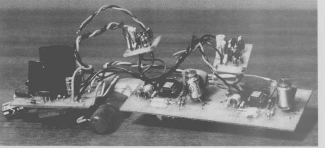
PHOTO 1: From the left are an experimental regulated power supply, two op amp RIAA stages, and two suspended, discrete “0002 ” buffers. Understandably superseded by new boards.
In retrospect, a person who never makes mistakes couldn't be expected to know how to fix anything. Due to a wealth of experiences, I can now fix practically anything, and herein share my good fortune with you. It's all a matter of practice!
Soldering
The introductory paragraphs in the first Heathkit instructions ever sold contained very clear text about soldering technique and its extreme importance to electronic circuits.
With an iron of proper wattage (15-25W), clean tip, correct temperature, heating both the lead and the PC board foil, you can make rosin-core solder wet out a joint and leave beautiful fillets.
The parts must be clean to begin with (and pretinned), and remain motionless until the solder hardens. However, I am not immune from producing a cold solder joint now and then.
These unseen, non-conducting joints manifest themselves very pointedly during 'listening tests’--particularly if the open circuit is the larger feedback capacitor in an RIAA network, and Carlos Montoya is playing a very hot sounding guitar. Such joints are infrequent if you heat the joint adequately the first time to cook out the flux.
Because of practice, I can lift the tiniest foil trace away from the substrate, away from a solder pad--this is circuit modification at its sincerest. A humble repair is then made by soldering a length of tinned, solid copper conductor on top of the damaged foil trace which leads to the hole with the missing solder pad. This reinforcement comes in handy when a small, light capacitor is replaced by a large, substantial polypropylene, which needs all the support it can get.
When you are adding bypass capacitors on the foil side of a PC board, it is possible to accidentally melt the corner of a film capacitor with the iron.
This usually shorts the capacitor. Just like a blind pig finding truffles, the odor of a melting capacitor tips you off and a repair should soon be made.
Oscillation
To keep things honest, I observe the signal of all newly finished projects with an oscilloscope. This has revealed unexpected frequency responses and “fat lines ” for signal traces. By switching the 'scope to AC and magnifying the fat lines in time and voltage, I discover tiny VHF oscillations are the cause. Two mechanisms have been corrected to eliminate these oscillations.
My most recent creative source of oscillation was the crossing of a plastic skinned electrolytic capacitor with the bare lead of a film capacitor. My pseudoscience rationalization- -"it's only 50V, and it's DC anyway; the plastic skin will insulate nicely"--didn't prevent the point of contact from becoming the site of a tiny AC leakage current. I fixed this with a little Teflon sleeving on the bare wire. Strangely, this fault had no audible effect, but the plastic eroded.
A more “electronic ” source of oscillation is associated with the addition of current buffers which are at the output of op amps and inside the feedback loop. In every successful application made to date, there is a 'decoupling resistor’ at the input and output of the buffer. If the feedback loop or load contains capacitors or inductors, then the new output decoupling resistor must be included in a circuit analysis of the application, or the frequency response may suffer.
In general, feedback circuits can oscillate if subjected to enough noise and have too little phase/gain margin. Most electronics handbooks and successful application schematics contain examples of how to ensure stability. These tricks can apply to wires connecting driver boards with power transistor base or gate leads.
Ratings
Sometimes a part which is too small is mounted in a stressful application. This has resulted in smoked resistors, melted insulation, short service lifetimes, and, if nothing else, compressed sonics. Re call my fondness for Teflon-insulated wire-it won't melt. A reversed electrolytic capacitor also makes a dandy fire cracker, as perhaps some of you can attest.
One telling stress test I performed is to insert op amps into a socket, one hole off (leaving two pins hanging out of one end of the socket). If they survive (not likely), try having just one pin miss its hole. A pair of needle-nose pliers or an IC installer/extractor tool eliminates most of these risks in IC assembly.
Current, voltage, and wattage ratings of components are usually a bit optimistic. I encourage experimenters to divide the published ratings by a well chosen integer number, to ensure choices favoring long lifetime and good response to electrical transients. The sonics of a circuit generally benefit from such de-rating.
PC Board Layout
A UV lamp, chemicals, and layout supplies make it convenient to fabricate experimental PC boards for test or custom applications. However, laying out boards is somewhat of an art, and a few suggestions here may improve the quality of any boards (OCSL offers a book on the subject-BKT18).
Since a board starts life being entirely copper-clad, circuits will benefit sonic ally if as much copper as possible is left on the board after etching the circuit.
Generous ground planes, wide conductor traces, large solder pads, and wire jumpers to carry power all help. Miniature board layout was attempted here and abandoned-the practical and electrical problems associated with very small foil traces are just too frustrating.
Many PC board foil patterns featured in TAA contain a few extra holes and foil traces. This is a convenient way to facilitate fine-tuning component values with added “trimmers, ”' provide test probe points, and add some flexibility in circuit application.
Component layout can be problematic. A very successful version of the Chris Paul buffer! was made, followed by a physically shrunken version for a more cramped installation. The “'shrunken ” version oscillated, there fore you know that component proximity and orientation are important in certain circuits.
Circuit Analysis
A successful circuit generally follows a successful circuit analysis (seldom the reverse). With good computer power in expensively available, circuit simulation is a practical reality for home electronics buffs.
Serious circuit designers save time by using PSpice, or similar circuit analysis software. These codes assemble a simulated circuit from the user's component and interconnection specs, then operate the circuit mathematically.
Since my circuits are simple, it is convenient to write impedances and per form circuit analysis by hand, then transfer them into PASCAL. I have assembled a library of complex functions to do the series-parallel algebra, and the program uses a loop through a table of frequencies to provide the response curve points.
If a response curve must be optimized, for example the RIAA curve, the ideal is entered (in dB) as a tabular function of frequency. Subtracting the ideal from the computed circuit response yields an error column, which is then used during man-in-the-loop circuit optimization trials. This method also shows the analyst where the circuit is sensitive to parts-tolerance deviations, if out-of tolerance values were supplied. Computed component values are then duplicated during assembly, by choosing among measured samples and/or fine trimming.
Originally, I performed mathematical reduction of the circuit analysis, yielding rational functions, coded into PASCAL. I found two perilous features by using this method. First, the algebra is clumsy, voluminous, and prone to human error. Second, the reduced algebraic forms, when supplied with numerical values, were often unstable.
This numerical instability is caused by sensitivity of the equations to the finite number of computer bits used to approximate real numbers.? Instability can be conquered with additional algebraic 'cleanup,' but the total effort involved is greater than the “calculator ” method.
---
The Author:
Darcy Staggs has been interested in electronics and its magic since building a crystal set in grammar school. This elementary model was later equipped with the first commonly available transistor amplifier, aGE 2N107. A college education (MS, engineering) was followed by work on the Apollo Lunar project (simulation of the electrical power system), war gaming, management software for Swedish IBM, weapons system simulation, and successfully raising two sons, who also love good music.
----
Troubleshooting
I have a collection of test instruments which have accumulated over the years. An ancient VTVM is now accompanied by a 10MHz oscilloscope, a digital test meter (volts, amps, ohms, hertz-very useful), a capacitance meter, and a couple of ratty audio signal generators.
Also, I have looked over the shoulder of many skillful friends, who didn't panic, but proceeded methodically. This experience is a real asset.
The technical literature for every thing electronic in the garage and house, (stereo included), is maintained in a file. This is indispensable. Repair usually begins with checking fuses and cables, then isolating the sick component, followed by popping its hood and looking at the power supplies.
If the DC voltages check out (also DC voltages on all transistor leads), then a signal is injected at an input and examined on the oscilloscope, stage by stage, to the output. This usually reveals the culprit-an open or shorted circuit element, solder joint, or “dead ” transistor. I once blew up the left channel of my DH-220 amp due to the circuit interdependencies. In desperation I installed Teflon sockets for all transistors. This handy move facilitated testing each transistor out-of-circuit, with a simple VOM. Problem solved.
Troubleshooting is well documented in Homer L. Davidson's Troubleshooting and Repairing Audio Equipment, (avail able from Old Colony Sound Lab, PO Box 243, Peterborough, NH 03458, (603) 924-6371, $18.95 plus $2 S/H).
De-bugging requires significant “sleuthing ” ingredients. Doing a mental failure-mode analysis while studying the schematic helps, along with generally being prepared to accept any type of fault. Intermittent faults are worst--such as an inter-stage coupling capacitor in a tube amplifier. Once you find the problem, replace all similar caps-a great chance to upgrade component quality.
POOGE, Progressive Optimization Of Generic Equipment, means a lot of cut-and-try improvements based on having both a good grasp of electronic fundamentals, and a nose for finding suspect implementations in the hardware. Tips and examples of all kinds abound in TAA.
“POOGE ” as a term first appeared in TAA in 1981. Some categorical definitions may be useful. Upgrading a stereo component can be attacked at several levels:
Circuit element upgrades are straight forward-replace components part for-part with better quality and some times different values. Capacitors and resistors receive the same attention, as do wiring, controls, and so on.
Added circuit refinements generally don't alter the topology of the original design significantly, they just add to it. Regulated power supplies, DC off set servos, fancy volume controls, and bias current circuitry are in this broad category.
Circuit topology modification implies new circuit design in some part of the schematic. One extremely successful example of this, accompanied by equally lucid documentation, is the milestone CD modification work by Jung and Childress.
Modifications in these categories ad dress faults inherent in real-world components, overcome budget-mindedness in original designs, and respond to the rising popularity of new topologies. Any hobbyist with a little motivation, and a thirst for better sonics can achieve great advancements.
Some components (especially capacitors) are in innocuous-looking places in the circuit. Don't ignore them-as a trial improvement would quickly demonstrate. If it's there, it's suspect.
Conclusion
No one accumulates practical experience quicker than the wielder of the blazing soldering iron. Only the tinkerer will hear conclusively whether an enhancement succeeds, and by how much. It all matters; ultimately, a thoroughly POOGEd stereo system will outshine all but the most gilt-edged commercial units. Your pleasure will be exquisite when you cruise the displays at a high-end stereo exhibit and listen to sounds equaled by your own meticulously doctored components. And, it feels good to know how and why.
--------
REFERENCES
1. Paul, Christopher, The Buffer, TAA 1/88, p. 23.
2. Dahlquist and Bjorck, Numerical Meth- | ods, Prentice Hall, 1974.
3. Hollander, Chuck and Walter Jung,
“Modifying the Marantz 7C or St. Pooge and the DRIAAGON, ”' TAA, 1/81 p. 20
4. Childress, Hampton and Walter Jung, “POOGE 4: Philips/Magnavox CD Player Mods, ” TAA 1/88 and 2/88.
---------
Also see: