BALANCING DIFFERENTIAL CIRCUITS
THE COURSE of fine-tuning our systems, we sometimes solve problems that are of little or no consequence while other larger problems go unnoticed. To wit, notice the many RF (radio frequency) and over-voltage protection filters and devices on the market. I also call into question the so called 'balanced' inputs intended to reduce some forms of noise pick-up. In fact, most of us do not experience RF problems coming in on utility alternating current (AC) lines, and our systems are not plagued with common-mode noise pick-up on the cables.
For many audiophiles, I believe the extra expense of filters, line conditioners, and differential input/output systems available to fix the problem noted above make little or no improvement in an already quiet system. While some benefit from these products, for the most part the problems they fix are not prevalent. To be sure, current audio technology is not the victim of a sudden plague of damaged equipment blamed on over-voltage “spikes ” or surges on the AC-power mains line.
In a similar manner, “balanced” circuits appear to be a solution looking for a problem, which would presumably be noise. Oddly, many amplifier designers overlook why we use differential input circuits for balanced or unbalanced signal inputs: to reduce the output cur rent from the differential-mode components in response to common-mode input voltage.
Tipping the Scales
Obviously, the best circuit designs synthesize the best ideas presented to date. Then, the first step would be to explore design criteria and their basis.
Erno Borbely's latest preamp/amp design, found in “The New Borbely Preamp: The Modules , ” is an excellent example of combining the ideas of many into one. The resulting blend of engineering and synthesis provides an applications approach to designing. To that body of understanding concerning common mode signals, I would like to suggest something to improve the design of differential circuits and which is more than just lowering or reducing the likelihood of picking up noise: balancing differential circuits.
Before we attempt to reduce the effects of common-mode signals, we need to understand what they are and where they come from. For a broad technical overview, read “Common-Mode Signals ” (Audio, Feb., 1988). As stated therein, in a differential input circuit: "The common-mode signal is the average of two signals, 0.5 (e1 + e2), " where e1 and e2 are voltages between each signal conductor and the zero reference conductor. Because sine waves (commonly used for testing amplifiers) register an average level of zero, common mode induced distortion is not visible and it will not appear in measurements.
Music signals, however, are not wave form symmetrical and have nonzero average-voltage levels. Instead, they contain common-mode signals within themselves (Fig. 1).
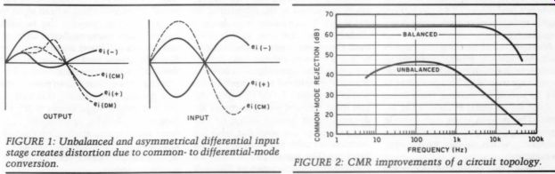
FIGURE 1: Unbalanced and asymmetrical differential input stage creates distortion
due to common- to differential-mode conversion. FIGURE 2: CMR improvements
of a circuit topology.
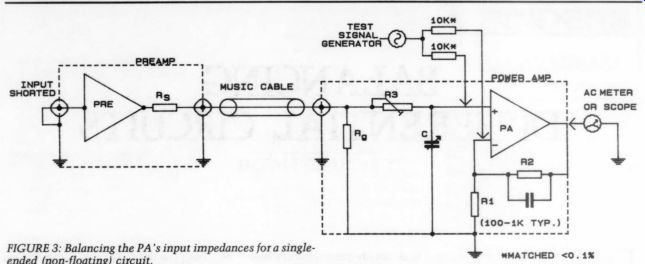
FIGURE 3: Balancing the PA's input impedances for a single ended (non-floating) circuit.
Because a common-mode signal is the average level of the signal, it is imperative to balance the differential in put stage. Each side of the differential pair or transistor must be symmetrical and match. Matching the component characteristics of one side of the differential stage to those corresponding elements on the opposite side improves common-mode rejection and decreases thermal drifts. This includes the source impedances seen by each side as well as transistor/tube mismatching, in equality of load impedances, and un equal voltages and currents. They must all be balanced.
Standard Rejection
Just because a circuit accepts a floating input signal does not mean it is a balanced circuit. For example, unequal in put impedances from each input to common contribute to errors. Figure 2 shows CMR improvements of a circuit topology similar to Borbely's line-level amplifiers (Hafler XL280, data circa 1985.) Borbely's (and others') TAA circuits are highly unbalanced in their input-stage impedances.
Nevertheless, balancing the impedance (AC) easily improves its common mode rejection seen by each differential input-stage transistor. This procedure is not as simple as making the circuit resistor values equal at each of the in puts. The process must also include source-output impedance driving the amplifier, which usually varies with frequency.
For now, this common-mode rejection improvement is not possible on a large scale because standard-source out put impedance does not exist. If we could settle on a standard--such as 50 or 100-Ohm--all power amplifiers would have the ability to offer their best common-mode rejection capability.
Indulgence
Figure 3 depicts how I tune a single ended (non-floating signal) power amplifier for better CMR (Common Mode Rejection). With the proper test equipment and experience, you can learn to improve the performance and sound of your audio equipment from this example. The object is to match the impedances recognized by each transistor's differential amplifier input. Generally, the side receiving the feedback signal registers the gain-setting resistor's approximate value, typically 100-Ohm-1k.
Now, if your source, or preamplifier, impedance is lower than this, we can add resistance to the source input (+) side of the power amplifier's differential stage to balance the two impedances (presented to the differential in put stage). If your source impedance is slightly higher, you may be able to re duce the preamp-output series resistor to a low enough value.
I applied the same signal to both in puts and monitored the output of the power amplifier. To do this properly, you must connect your preamp or audio equipment (turned on but no music) to your power amplifier with the interconnect cable you normally use for listening. The inputs (+) and (-) are connected by using a pair of 10K 1/4W resistors matched to within 0.1% directly to the FET gates of the power amplifier differential pair. When both input impedances are equal, common mode output from the power amplifier will be minimal. I inserted a small trimmer potentiometer (500-Ohm -1k-Ohm) on the power amplifier PCB in series with the input and a trimmer capacitor to ground in order to make the adjustments. I adjusted the series resistance at 1kHz and the added capacitance for minimum output at 20kHz. This method custom tunes the system for best performance.
If you change the equipment or cable, you must make the adjustment again.
Further improvements in CMR place circuit-topology refinements is beyond the reach of non-designers. Before we indulge in perhaps self-defeating, overly complex circuitry, let us at least get the circuits' input and output impedances truly balanced. It makes a difference.
If you find the results of balancing the differential stage convincing, you will agree that we are missing out on a very important area of testing and de sign. Designers can develop better balanced differential circuits from input to output if they consider the benefits beyond noise concerns. Better differential circuits will lower distortion due to the reduction in common to differential-mode conversion.
If analog is to continue to provide the best possible performance, standard in put and output impedances will go a long way in helping applications engineers and designers accomplish the task and take a “mysterious ” variable- equipment interaction-out of the subjective equation.
---------
---------
ABOUT THE AUTHOR: Richard Marsh has been listening to music and building his own audio equipment since he was a child. Since then, he has covered a broad range of audio activities. His recent interest in passive components culminated in a new capacitor design for which a patent is pending.
-------------------
Also see: