- About the Issue
- PUBLISHER ANNOUNCEMENT
- LETTERS
- Just Looking
- NEW CHIPS ON THE BLOCK
About the Issue
One of the motivations of AE readers is the conviction that there are always techniques to improve the performance of your sound system. A case in point is this issue's lead article by Gary Galo, who shows you a couple of factory-authorized upgrades-a chip piggyback modification and a rectifier mod--to Monarchy Audio gear ("Up grading Monarchy's Converters and Amplifiers," p. 8). Gary then follows this article with a detailed review of two power amps from Monarchy Audio-the SE-100 Delux and SM-70 ("Product Review," p. 28).
If you have a distorted view of square waves, be sure to check out Charles Hansen's "Square-Wave Audio Testing" (p. 14). Through the use of many simulations, he shows you how these classic system.
Have you discovered the advantages of synchronous rectification?
Michael Kornacker explains this technique for improving power-supply operation, without the use of diodes ("Try Synchronous Rectification," p. 26).
In "A DSO Trio, Part 3" (p. 34), Charles Hansen wraps up his trilogy on digital signal oscilloscopes with a look at the ADC-216 model from Pico. This 16-bit version is optimized for audio testing.
Finally, Charles Hansen, who, along with Gary Galo, was a real work horse this issue, keeps us up to date on the latest audio chips available on the market ("New Chips on the Block," p. 46). He examines the AK4528 24-bit Audio CODEC from Semiconductors.
A Major Announcement FROM THE PUBLISHER
My friends, Just over 30 years ago we set out on a journey into publishing a magazine about audio construction with high hopes and not a little apprehension. | feel that we are at a very similar threshold here in the last quarter of 2000. | am very pleased to announce the launch of a brand new periodical, audioXpress, whose first edition will mail to you in late December.
audioXpress will combine Audio Electronics, Glass Audio, and Speaker Builder in a monthly magazine. As a subscriber to one or more of our cur rent titles, you will be receiving the new periodical for the full number of issues for which you have already subscribed. This means that whatever number of magazines are left in your current subscription(s) will be mailed to you on a monthly schedule. If you subscribe to two of our magazines, we will add together the number of each remaining in your subscription and extend your audioXpress subscription for that number of issues.
Why Are We Doing This?
First, we expect to build a balanced periodical for you which will contain the same number of articles, or more, on electronics, speakers, and tube gear, respectively, in the course of 2001 and be yond. There will be larger coverage of new products, letters, and show cases of equipment. There will be a major expansion of the review section, which will include all manner of equipment in which any audiophile might be interested.
Second, we believe it will strengthen our effort to offer you a magazine about audio design and construction which will be larger and more powerful. It will increase the effectiveness of advertisers' in vestment in ad space. It will, we believe, attract some advertisers who have never been interested in our smaller-sized periodicals.
Three, it will give us space to expand our reviews of all kinds of equipment, which broadens our coverage of the audio field. Since we have wanted to offer more reviews, the broader platform of audioXpress will more naturally accommodate the entire audio chain.
Four, we hope that a combination of technologies will make it easier to deal with complete systems of components and the ways these interact with each other. I suspect that even the most dedicated glass enthusiasts have systems that are "hybrid" mixes be tween solid state and tubes.
Five, we will be coming to you every month, which should reduce problems about when you are going to receive your next issue. We will deliver multi-part articles with less lag time between installments. This speeds up correspondence inter change and provides faster answers to reader questions.
Each article's opening page will include a small icon which identifies its technology: tubes, solid state, or speakers. However, if you think about it, CD players, turntables, arms, phono cartridges, equipment racks, and cabinetry do not fit any one of our present periodicals better than another.
It is our intention to offer you everything you subscribed for in any one of our three current con sumer periodicals, with the added bonus of audio-related coverage for which you did not subscribe.
I, and all of us on our staff, deeply appreciate your loyalty and support over the more than 30 years of our existence. We hope you will continue to trust us to do our very best for all of your needs for audio technology information.
- E.T.D.
Just LOOKING
HAND-HELD OSCILLOSCOPE
Allison Technology Corporation has released the HH972, a hand-held digital storage oscilloscope and in-circuit component curve tracer. This device provides two useful test instruments in one package the size and weight of a digital voltmeter, so it is useful for a wide variety of applications. Its specific features include a wide 5SMHz bandwidth, power internal 9V battery or AC wall adapter, display of amplitude, time, and resistor value, 280V true RMS AC/+400V DC maximum input voltage, easy-to-use keypad control, 1M input impedance, and an optional stand with a rechargeable battery. Allison Technology Corporation, 2006 Finney Vallet, Rosenburg, TX 77471, (800)980-9806 or (281)239-8500, FAX (281)239-8006, atcweb.com.
VIRTUAL ELECTRONICS LAB
Protel International Ltd. has released CircuitMaker 2000-the "Virtual Electronics Lab." This new version of the popular CircuitMaker now provides complete schematic design, simulation, PCB layout, and autorouting in one box. Improvements include a new waveform viewer, a new device browser, and a streamlined user interface for easier access to various features. Instead of requiring users to purchase multiple products, CircuitMaker 2000 allows a designer to capture a design, perform advanced circuit simulation, analyze the operation of a circuit, and complete the design and testing with full-featured PCB design and layout capabilities.
Protel International Ltd., PO Box 427 Frenchs Forest, NSW, Australia 2086, +61 2 9975 7710, FAX +61 2 9975 7720, protel.com.
BOOKS
Focal Press has introduced two books, the paperback version of The Inventor of Stereo: The Life and Works of Alan Dower Blumlein, by Robert Charles Alexander, and Recording Spaces, a new book by Philip Newell. The Inventor of Stereo is the only book to date on the life and works of Alan Dower Blumlein, one of Britain's most important and most overlooked inventors.
This book contains many insights into the development of audio, electronics, and radar, as well as information that has been considered top-secret until the release of this book. Recording Spaces deals with the acoustics of rooms intended for musical performances of varying styles.
This book is easily accessible for different levels of understanding of its subject matter and combines easy reading with technical and scientific accuracy. Focal Press (imprint of Butterworth-Heinemann), 225 Wildwood Ave., Wobum, MA 01801-2014, (781)904-2500, FAX (781)904-2620.
MWHIGH-POWER MOSFETS
Richardson Electronics is now offering new MOSFETs, POWER MOS VI, from Advanced Power Technology (APT).
These devices use APT's patented metal on polysilicon gate structure to provide low capacitance, low gate charge, and extremely fast switching. Applications for these devices include DC/DC converters, power factor correction (PFC), pre regulators, switchmode power supplies, welders, UPS, motor controls, and inverters. Other features of the POWER MOS VI family of MOSFETs include 500V breakdown, 50 to 200 m<2 on-resistance, and 26-77A drain current. Richardson Electronics, Ltd., rell.com.
Pocxer Score
DIGITAL A/V RECEIVER
Onkyo has introduced its most affordable digital home theater (AN) receiver to date. The Onkyo TX-DS484 is a 5.1-channel, 5 x 55W receiver with digital decoders for Dolby Digital, DTS, and Dolby Pro-Logic movie sound formats, connections for multiple analog video sources, music inputs for a CD-player, audio tape player, and a turntable, and an AM/FM tuner. The TX-DS484 also has premium sound quality features; Onkyo's Wide Range Amplifier Technology (WRAT); inputs for three video sources; and a speed-sensitive volume control. The system has a brushed aluminum front panel and a bright fluorescent display.
Onkyo USA Corporation, 200 Williams Drive, Ramsey, NJ 07446, (201)825-7950, FAX (201)825-8150, gspr.com.
PUBLICATIONS
Howard W. Sams Company has spun off the Technical Products Division (Photofact and Prompt Publications) into a new, separate company called Sams Technical Publishing. The free 2000 Technical Book Catalog, with listings of over 200 publications and an index that allows you to find books based on subject, title, or author, is now available from Sams. Howard W. Sams and Co., 2647 Waterfront Parkway E Drive, Indianapolis, IN 46214, (800)428-7267, samswebsite.com.
Herbach and Rademan has recently released its latest catalog, Products for Science and Industry This Month. It features test and measuring equipment, power supplies, electronic components, accessories, and more for all of your electronic needs. Herbach and Rademan Co., 353 Crider Ave., Moorestown, NJ 08057, (800)848-8001, FAX (856)802-0422, herbach.com.
LETTERS
ERRATA NOTICE
Within the article "Improved Positive Negative Regulators" (AE 4/00), the captions of Photos 4 and 6 are swapped. For the display to make proper sense, trans pose the caption text between these two figures, leaving the photo numbers and the respective photographs just as they are shown.
Walt Jung Fallston, MD
A NETWORK OF IDEAS
Dr. Norman Thagard's ongoing series on the A40M amplifier has been a pleasure to read, both for its subject matter and for its wonderfully detailed exposition of the design. In particular, his two-stage description of voltage doubler operation, appearing in Part 5 of the series (AE 3/00), offers the clearest explanation of this circuit I've seen.
As Dr. Thagard points out, the usual full-wave voltage doubler is not suitable for this application because its output voltage floats with respect to ground.
For this reason, he opts for the half-wave doubler (with its ground-referenced out put), despite its having increased ripple voltage under load. In part to compensate for the latter deficiency, Dr. Thagard provides separate voltage doubler circuits for each stereo channel, thereby cutting the load for each in half.
While I find no fault with this approach, I would like to suggest an alter native that may be useful where space or other considerations dictate the use of a single front-end voltage doubler circuit for both stereo channels. Figure 1 shows how two bridge rectifiers may be connected across the transformer secondary to produce positive and negative voltage doublers that are both full-wave and ground-referenced.
The inputs to each bridge rectifier are connected across the secondary (which must have a ground-referenced center tap) by way of capacitors, which are part of the voltage-clamp portion of the doubler. The outputs of each bridge are connected between ground and another capacitor, which is part of the peak-detector portion of the doubler. The polarities of these connections are such that positive and negative output voltages are produced. (Each polarity operates independently of the other, and one may be omit ted entirely in designs that need only a single output voltage.) To provide equivalent performance, each capacitor in the voltage-clamp portion of each doubler should have the same value and voltage rating as the equivalent capacitor in Dr. Thagard's circuit. If the capacitor in the peak-detector portion of each doubler has the same value and volt age rating as Dr. Thagard's circuit, two channels should be able to draw current from one supply with the same ripple voltage obtained when using separate half-wave circuits for each channel.
Joe Berry
Norman Thagard responds:
It is amazing to me how things happen in pairs or even threes. I had been curious about the possibility of ground-referenced full-wave volt age doublers, even to the point of wondering about, but never examining, the use of a bridge rectifier to realize such a doubler.
A month ago 1 was reading Tube CAD Journal on-line. I discovered that a full-wave voltage doubler schematic was depicted in the January 2000 issue. The circuit was identical to the upper (positive) doubler that Mr. Berry offers.
I thank Mr. Berry and Tube CAD Journal. I would advocate the use of the full- wave over the half-wave variety in most circumstances, especially where the current draw is more than a few tenths of an amp. Be aware that some have said that 60Hz hum is less annoying than 120Hz hum. While this would seem to favor half-wave doublers, a good power supply should filter the ripple sufficiently to render any hum inaudible.
I would ask that Mr. Berry check the bridge rectifier arrangement for the lower (negative) voltage doubler. It appears to me that this rectifier would also try to produce a positive voltage with the polarity of the electrolytic capacitors reversed.
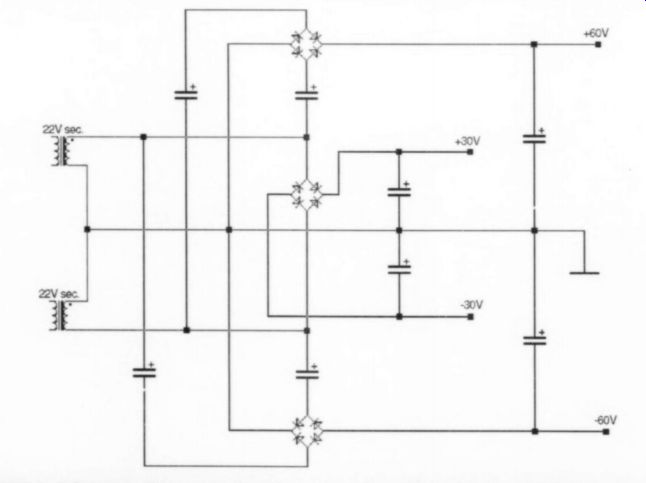
FIGURE 1: Schematic demonstrating the connection of two bridge rectifiers across the transformer secondary.
MORE FORUMS FOR DISCUSSION
Perhaps I missed it, or maybe you have already considered this, but I suggest that you establish forums for discussions of articles in your magazines. While there are plenty of newsgroups that deal with audio electronics, I believe that your readers (such as myself, a sub scriber to Audio Amateur since 28 years ago and to Speaker Builder from its inception) would find this useful. While the magazines provide some opportunity for this, the dialog is primarily with the article's author. This would provide an opportunity to learn from others with knowledge or experience relating to the subject matter of the articles.
Terry Iardi, Dobbs Ferry, NY
Comment on "AUDIO AID"
In "What's a VU?" (AE 3/00), the author does a good job of defining what a VU meter really is. He even explains why the "0" point on a conventional, unamplified VU meter has to be at least +4. However, there's a glitch at the very end. Professional broadcast analog audio gear is expected to reach at least +24 (not +18) be fore clipping.
In the good old days, broadcast plants (in the U.S.) were aligned on +8. This was the level you got when you put up a tone and ran the fader until the VU meter read "0". This was variously referred to as tone level, reference level, or zero level.
A crest factor of 8-12dB was added above that for "peaks of frequent recurrence." Most plants standardized on +16 s "peak" level, which was the maximum level program peaks were expected to reach. Another 8dB were added above peak level for headroom.
Program peaks were not expected to extend into this area under normal circumstances, but they could without driving the plant into clipping. Clip level was +24. These levels are still basically standard, except that many broadcast plants now align on +4, which follows recording studio practice.
The advent of digital equipment mud dies the issue somewhat. Digital gear be haves like an AM transmitter in some ways. There is a maximum input level above which you cannot go-once you reach all ones, there isn't any more. You I need a metering device that allows you to stay close to, but not go over, the maximum available level. This has led to the modern fast-attack LED-type meter with "0" at the top of the scale and the reference level point at -20.
I've gone on longer than I intended and have probably provided more data than you wanted, but we old broadcast engineers-I've got over 30 years in the business-tend to ramble on.
Louis Brown
Bill Ruck responds:
There are very few "standards" regarding broadcast levels.
The only one that was ever formalized is about 60 years old. In the January 1929 issue of The Bell System Technical Journal the "decibel" was introduced. (Note that the not capitalized at that time.)
In 1938 the "New Standard Volume Indicator and Reference Level," which we currently call the "VU Meter," was introduced. This was the "b" was result of a joint effort by the Bell Telephone | Laboratories, Columbia Broadcasting System and the National Broadcasting Company. Until that time there were multiple reference levels reference meters, and reference impedance After this point the "standard" for program level was "+8 VU," which means that program material monitored on a "standard VU Meter" at "zero"-on the VU Meter this level was equivalent to +8dBm with a steady tone. Further studies established a 10dB "peak to average ratio" that became a maximum transmission level of 10dB above +8dBm (tone), +8 VU (program material), or +18dBm.
Through much practice, +18dBm has become firmly engraved in stone as standard in most transmission applications. The technical references for Bell Operating Companies still refer to a program output of +8 VU and +18dBm instantaneous peak values. Satellite transmission equipment is designed for +18dBm maximum.
The audio paths of most videotape recorder are designed for +18dBm maximum (and some don't even make that maximum level).
Since most broadcast transmission applications are sending processed audio and not "live from the microphone" audio, this works adequately if one understands the dynamic range limitations of the transmission media. However the recording industry and many broadcast operations are now standardized with "zero" on their VU meters being equivalent to +4dBm with a steady tone (+4 VU). Most equipment today will pass peaks above +20dBm (vary in from +22 to +26 depending on design).With "live" material, it makes perfect sense to have more peak headroom.
Even in "the good old days" program amplifiers were expected to pass peak levels in this range; some would even pass above +30dBm without clipping. There is an advantage to out put transformers and 600 ohm matched impedances: low impedance transistor amplifiers could be stepped up to 600 source impedance with a corresponding increase in level. How well these program amplifiers sounded is a very different subject-those of you who still remember the RCA BA-43 will nod your heads. The European community developed a totally different mentality towards monitoring program material; they prefer peak indications rather than the average indications of the "standard VU meter." Further complicating broadcast level definitions is the FCC establishment of totally different requirements on transmitter modulation.
Because transmitter modulation is a peak function, and FCC standards expected you to hit (but never go over) 100%, modulation monitors had deliberate peak calibration requirements.
Some time ago the FCC dropped those meter specification requirements but they are, again, firmly engraved in stone in transmitter modulation requirements.
While stations are still prohibited from exceeding 100% modulation, they can use any sys tem they want (including nothing) to monitor their modulation. (Even though the FCC mandated that stations operate and maintain modulation monitors meeting FCC specifications, the FCC itself didn't use modulation monitors to measure a station's audio performance.) The expression "peaks of frequent recurrence" mentioned in Mr. Brown's letter is an old FCC term from the days of modulation meter standards.
Because there is audio processing between a radio or TV station's console and a transmitter, what you see on the console VU meter does not correspond to what you may see on a peak modulation meter or even on a VU meter monitoring the input of the transmitter. Modern broadcast processing provides absolute peak control (peaks really do hit "100%" all of the time), plus loudness enhancement. Furthermore, FM and TV processing must work around a substantial high frequency boost (75us pre-emphasis).
Generally today (if the processing is set reasonably) once program material starts to peak around -10 VU the transmitter modulation reaches 100% and after that does not change. If the level is increased until the VU meter is hard against the stop one will not hear or read a difference until something clips. (Note: this is an "average." Some, notably non-commercial stations really do have dynamic range. Others have even less dynamic range; if there is any signal it will be at 100% modulation.) I have always set my digital equipment so that "zero" on a VU meter at +4dBm (+4 VU) is -18dBFS digital. At this point the analog amplifiers are near clipping at 0 dBFS. Most digital interface standards are around this point, which allows a traditional VU meter to work well with digital equipment. So far I have not seen a problem with digital peaks at 00 dBFS as long as the VU meter is "on scale", indicating that live pro gram material has less than an 18dB peak to average ratio. Obviously, if something "pins" the VU meter, all bets are off.
A problem today is that current, highly processed CDs have a peak-to-average ratio of near zero. If you calibrate your system for -18dBFS from the CD player output at +4dBm it will appear to be "hot" on the console by 6dB or more. Although there won't be any distortion since the peak level does not exceed 0dBFS or +22dBm, it is hard to mix music when very "hot" levels limit the fader travel.
HELP WANTED
I am looking for the schematic of the PAS 3 Series 2 Dynaco preamp (1994). The high voltage section is not supplying the necessary voltage (the green light on the front glows dim). It sounds as though it has dead batteries.
Chris M.
NEW CHIPS ON THE BLOCK
AK4528 24-Bit Audio CODEC
By CH
AKM Semiconductors has produced what they claim is the world's highest performance, 24-bit 96kHz audio CODEC (encoder-decoder) for high-end consumer and professional audio applications. The AK4528 is reported to be an ultra high-performance, two-channel, 24-bit CODEC for use in 96kHz audio recording systems.
The ADC section features 64x over sampling with full differential inputs. The dynamic range is 107dB and the S/(N+D) figure is 94dB. The front end includes a digital HPF for offset cancellation, essential for minimizing spurious signals.
The DAC section is a 128x over sampling delta sigma modulator with a 24-bit, 8x over-sampling digital filter achieving +/- 0.005dB passband ripple and a stopband attenuation of 75dB on differential outputs. The DAC dynamic output range is 110dB with S/(N+D) at 94dB. A de emphasis filter for 32kHz, 44.1kHz, and 48kHz sampling rates, together with 128 level digital attenuation, and soft mute are included. The DAC architecture uses AKM's newly developed Advanced Multi-Bit architecture that achieves low out-band noise and high-jitter tolerance through the use of SCF (switched capacitor filter) techniques.
Both the ADC and DAC sections inter face to the digital world using a variety of interface standards, including I2S, making it simple to connect to a DSP. The AK4528 supports a master clock ranging from 256fs to 1024fs since it incorporates an internal clock divider.
The AD4528 comes in a 28-pin VSOP package and requires a single 5V DC supply (3V DC pin available for 3V I/F).
Prices are $5.77, and an evaluation board is also available.
For more information call Richard Kulavik at (888) 256-7364, or visit akm.com.
--------
Also see: