This article describes a simple power-supply mod for the NAD PP-1 phono preamplifier, which the author reviewed in AE 3/00.
The PP-1 is a cost-effective out board phono preamp, with an RIAA circuit difficult to fault at the asking price of $129. The RIAA accuracy is surprisingly good for the money.
The only problem I find with this pre amp, considering its cost, is the power supply regulator (Fig. 1, top), a single LM317 adjustable model. Positive and negative rails are made by creating a chassis ground point midway between the regulator output and the DC power input ground. Strangely, the LM317 isn't configured as a regulator, but as a current limiter. As such, it doesn't regulate at all. The DC output rails vary with the AC line voltage. Neither does this configuration provide adequate ripple rejection. There is a 6 to 7mV pk-pk ripple on the positive and negative rails.
Simple Design
This modification reconfigures the LM317 as a true regulator (Fig. 1, bottom). The design of this mod didn't require an advanced degree in electrical engineering--it's right off the National Semiconductor data sheet, and is a standard means of configuring three-terminal adjustable regulators. The current-limiter configuration is sometimes used in battery-charger circuits, but I fail to see the reason anyone would use a similar scheme for an audio power supply.
To modify the preamp, you will need two resistors, 100 ohm and 1.21k (both 1/4-W, 1% metal film), and a 120uF, 25V electrolytic capacitor. You will also need two 1N4002 protection diodes. Refer to the schematics in Fig. 1, which includes the LM317 W, pinout, and the parts list, Table 1. Proceed as follows:
Remove the four case screws.
Remove the LED from its plastic holder.
Remove the four PCB mounting SCTEWS.
Replace R19 (62 ohm) with a 100 ohm , 1/4W, 1% metal film resistor. Leave 1/4" of resistor lead above the PCB to facilitate attaching additional components.
Solder a 1N4002 diode (Da) across R19 on the component side of the board. The cathode (banded end) should face the center of the PCB.
Unsolder the R20 lead closest to the edge of the PCB. On the component side of the board, solder this lead to the R19 lead furthest from the board's edge, which is also the cathode of Da, as well as the junction of R19 and the regulator output. Photo 1 shows the changes to the component side of the board.
--------------
TABLE 1: PARTS LIST
(1) 100 ohm, 1/4-W 1% Yageo metal film resistor, #100X-BK-ND
(1) 1.21k, 1/4-W 1% Yageo metal film resistor, #1.21KX-BK-ND
(1) 120pF, 25V Panasonic HFQ electrolytic capacitor, #P5698-ND
(2) IN4002 diodes, #1N4002MSCT-ND
--------
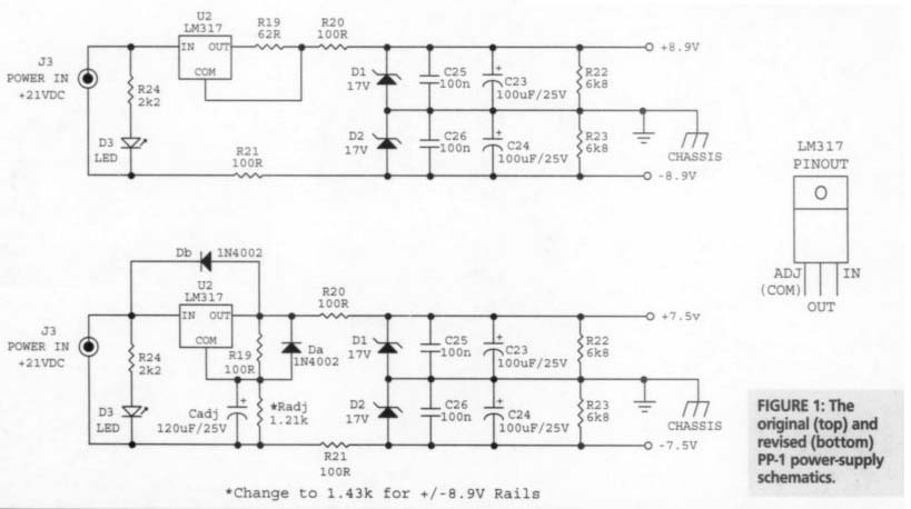
FIGURE 1: The original (top) and revised (bottom) PP-1 power-supply schematics.
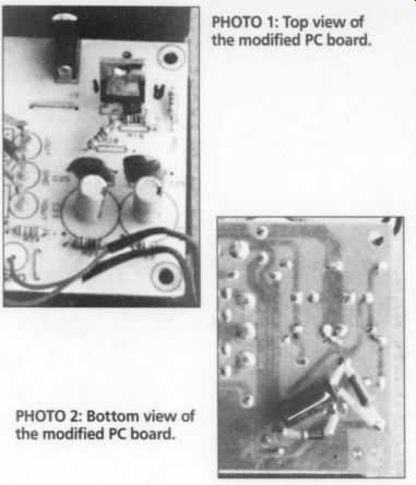
PHOTO 1: Top view of the modified PC board. PHOTO 2: Bottom view
--------
On the foil side of the board, solder a 1N4002 diode (Db) between the regulator input and output. Use sleeving on the diode leads. The cathode is connected to the regulator input. Make the cathode connection to the PC trace that goes straight back to R24 at the front edge of the PC board.
On the foil side of the board, solder a 120uF/25V electrolytic capacitor C0 between the vacant R20 hole and power-input ground, which is the R21 pad closest to the front edge of the board. The negative-capacitor lead connects here. Be sure the capacitor case rests flat against the board, and not against protruding component leads Use sleeving on the capacitor leads.
* Now solder a 1.21k,1/4W 1%metal-film resistor (R 4) in parallel with the 120uF capacitor. Use sleeving on the resistor leads. Photo 2 shows the changes to the foil side of the board.
You might be tempted to eliminate the 100-Ohm series resistors, R20 and R21 in order to lower the regulator output impedance. I advise against this. The LM317 has some broadband noise at its output, visible on a scope. The R/C net works produced by these resistors and the filter caps provide substantial attenuation of this noise.
Cautious Powering-Up
I suggest powering up the preamp with a Variac, if you have one. As you increase the line voltage, alternately monitor the positive and negative supply rails to make sure they are headed in the right directions. The rails should reach a maximum of +7.5V DC across the filter capacitors.
If you look at the supply rails on a scope, they should appear ripple-free on your most sensitive gain setting.
You can also check the dropout voltage using your Variac. Lower the AC line voltage with the Variac until ripple appears, then carefully increase the line voltage until the ripple just disappears. Measure the AC line voltage at the Variac output. My modified regulator drops out of regulation at a line voltage of just under 105V AC, which I consider acceptable. The DC supply rails should re main stable at any line voltage down to 105V AC.
The modified regulator is a significant improvement over the stock supply, which is in a constant state of dropout and doesn't regulate at all. If you are concerned that the slightly lower rail voltages limit headroom, you can increase the adjust resistor to 1.43k. This will bring the supply outputs back up to the original +/- 8.9V, but it will also raise the dropout point. Note that two samples of the stock preamp I measured have +8.9V rails, even though the factory-supplied schematic shows them to be +/- 8.3.
The stock preamp will output 5.1V RMS at 1kHz prior to clipping, which corresponds to an input of 63mV.With +/- 7.5V rails, the preamp delivers 4V RMS at 1-kHz just before clipping, produced by an input level of 50mV. For most medium-output phono cartridges, +/- 7.5V rails should be fine.
Now, reassemble the preamp and give it a listening test. Sonically, this modest preamp now has some dynamics, punch, and life previously missing. The sound staging is also improved, and the bass has greater weight. This modification ad dresses the problem of the odd power supply configuration, adding only pocket change to the cost.
Digi-key: Thief River Falls, MN 56701-0677 1-800-433-4539 digikey.com
Also see: