Here are a couple of voltage-doubler circuits with full wave and "three-quarter-wave" rectification that will prove useful in some of your audio designs.
While working on a project, I needed a full-wave voltage doubler (FWVD) circuit for a dual-complementary (positive and negative polarity) power supply that utilized a grounded center-tap transformer. I looked through my library, but could not find such a circuit, so I began to experiment. Although I did not do exhaustive research, I came up with a successful solution that I had not seen published before.
Fig. 1 shows a well-known FWVD that you can use where it is not necessary that one side of the transformer secondary be at ground potential. Because of this fact, I could not get this circuit to work in my grounded, center-tap dual complementary configuration.
Reworking the Circuit
I needed an FWVD that could have one side of the secondary grounded (the center-tap). Half-wave voltage doublers have this feature, but I needed full-wave rectification. I set up the half-wave circuit in a dual-complementary configuration (Fig. 2), and began to experiment to see whether I could convert this to full-wave rectification while preserving the voltage-doubling feature.
I first noticed that the circuit (Fig. 2) looked similar to a full-wave bridge circuit, so I thought it might work to add diodes crossing from the secondary outputs to the opposite DC outputs (Fig. 3).
The result was what I call a three-quarter-wave voltage doubler, for lack of a better name. You can see from the raw DC ripple (Fig. 4) that the characteristic empty spaces of the half-wave waveform are now filled, not with doubled-voltage, but unity-voltage pulses.
With an output filter capacitor attached and the circuit under a load, you can see a slight "bump" in the ripple ramp where the unity pulse resides (the dashed line of Fig. 4). This would seem to provide a lower limit to the dip in the ripple voltage under a heavy load. Unfortunately, it's not true full-wave rectification, but it might prove useful in some designs because of its simplicity and low parts count.
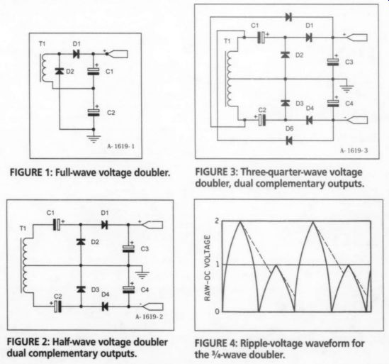
FIGURE 3: Three-quarter-wave voltage doubler, dual complementary outputs. FIGURE
2: Half-wave voltage doubler dual complementary outputs. FIGURE 4: Ripple-voltage
waveform for the 3/4-wave doubler.
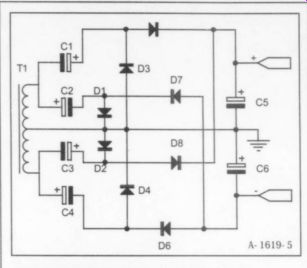
FIGURE 5: Full-wave doubler, dual complementary outputs.
Well, with that, I looked at Figs. 2 and 3 again and saw another possibility (Fig. 5). Although it has a large parts count, this circuit fits the bill. It is a voltage-doubler with true full-wave rectification, operating from a grounded center-tap trans former. If you wish to know how it works, consult a description of a half wave voltage-doubler, then apply the concept of a full-wave bridge circuit.
Points to Note
There are some important matters to consider for these two circuits. The capacitors connected across the outputs must have a working voltage rating of more than the doubled output voltage but the in-line capacitors need only to be rated for greater than the unity voltage The diodes should have a current rating greater than the load will draw, and, to e on the safe side, the peak reverse-voltage (PRV) rating should be greater than double the peak transformer secondary voltage.
Also, since the in-line capacitors must ass the full load current, use only top-the-line capacitors, because the ripple voltage that appears across the capacitor increases as the load increases. If the current is too high, it will cause heating and deterioration of the capacitors. You can educe this by using high-quality, high value capacitors.
ES American Radio Relay League Handbook. ARRL
Also see: