
Anyone working in broadcasting is surrounded by machines. Without them, the jobs would vanish. It only makes sense, then, to have an idea of how they work, what their principles are, and what they can do for you. Further, the more you know about how they work, the better able you will be to figure out if you can do something new with them that no one else has thought of. If you know enough about the machine to know your idea is physically impossible, then you can drop it. But no idea ought to be dropped till you reach that point. The most creative broad casters know enough about the equipment to know when to push for a different approach and when to shut up. That takes knowing how things work. Also, knowing how the equipment works will help you avoid doing damage to it. Since you don't want to hurt the tools of your trade, knowing how they work becomes doubly important.
TELEVISION CAMERAS
A magician changes one thing into another. There are many natural processes that change one thing into another, such as cold temperatures changing water into ice. And there are some machines specifically designed to change one thing into an other, like the machines that change raw plastic into records.
A television camera is one of those machines that change things-it changes light energy into electrical energy. The light falls on a subject and is reflected into the camera. If there is enough light to activate the camera at all, certain things will happen inside of it. That's like your eye. If there is only a dim bit of light, you may not be able to see anything.
But if there is enough light reflected off of objects, you will be able to see them because of what goes on inside your head with that reflected light. Let's take this analogy a bit further.
Light is reflected into your eye, where the retina at the back of your eyeball breaks it up into little bunches. Each bunch causes a particular response by a portion of the retina, and that response causes some stimulation of the optic nerve. When this nerve is stimulated, it sends a particular pattern of electrical energy to the brain, which then interprets the electricity in certain ways and causes you to see. So vision is not so much in the eye as it is in the brain.
A television camera works much the same way. The light is reflected into the camera, where it is broken down into bunches called lines. These lines stimulate various pieces of equipment to send out electrical signals, which travel to the cable and out of the camera to master control. In master control, these signals can be turned back into a picture. So the picture is not in the camera so much as it is in master control.
OK, let's look closer at what happens to the light as it enters the camera. This light carries colors with it (by virtue of the frequencies involved), and these colors get split up by a prism. The red colors go to a red pick-up tube, the blue to a blue one, and the green to a green one. All pictures of light can be broken up into those three colors, and all colors, even yellow and orange, can be made from light of those three colors. Now these pick-up tubes are like the retina of the eye in that they are sensitive to light and react in certain ways. But they can't react to a lot of light any more than the retina can. So as well as breaking the scene down into the three colors, they have to break it down into smaller units of light.
That's where the lines come in. Let's just take the green pick-up tube as an example. All the green light from the scene falls on the green tube. Inside the tube is a coating of phosphors which will glow as the light hits it. In places where a lot of green light hits it, it will glow brightly. In places where little green light hits it, it will glow very little. As it glows, a beam of electrons from the back of the tube is sent up to the front.
This is a narrow little line of electrons; and it gets pushed across the coating of phosphors, but it covers only a thin little line of them. If the phosphors are glowing brightly, the electrons get very stimulated. If the glow is weak, the electrons are hardly excited at all. So the beam of electrons reacts to light exactly as it is bright or dark. Here's the kicker-a flow of electrons is an electric current. That's a definition. So we have changed the light into an electrical current by this process, and this current represents the light and dark areas. If it's bright, the electrons are really stimulated, and we can say we have a stronger flow of electricity. It's the reverse if it's dark. But this beam of electrons is small and covers only a narrow line of the phosphors. That's not the complete picture, so we have to send a beam of electrons out to a spot below where the first beam went across the phosphors. After the first beam goes across the picture, we start that beam over again, but down lower, and back to a neutral level of energy. We do that over and over again and thus break the picture down into lines. Those are the small bunches we needed for the pick-up tube to handle.

FIG. 1 Picture traced by lines
All this has to be done fast, or the picture will change out in front of the camera before we are through. Our electrical system operates on a 60-cycle-per-second basis, so we can most conveniently tie into the number 60 as a basis. Since our picture needs to be fairly clear, we want quite a few lines. If we used only 10 or 20 of those narrow lines to make a picture, we'd have no detail at all. So what our system uses is 525 lines.
And we get those 525 lines every thirtieth of a second, which is a doubling of the 60-cycle-per-second basis. In a sixtieth of a second, we get half the lines, and in the second sixtieth of a second we get the other half. There are good reasons for not doing the whole 525 lines in a sixtieth of a second.
First of all, it's easier to build the machines to operate at a lower speed. And a thirtieth of a second, even though it's fast, isn't as fast as a sixtieth. Then there are some moves which are faster than a sixtieth of a second, so the picture changes faster than we can really manage. So by showing half of how things were in the first sixtieth of a second, and how things are on the other half in the second sixtieth, we can get an average that comes pretty close to what really happens. That first half of the picture is made up of all the odd-numbered lines. Obviously, the second half is all the even-numbered lines.
So in the first sixtieth of a second we get lines 1, 3, 5, 7, and so on. Next we get 2, 4, 6, 8, and so on. These half pictures are called fields. You have one field every sixtieth of a second.
Two fields together make up a complete picture, and that is called a frame. Frames take two-sixtieths of a second, of course, or one-thirtieth. Therefore, you have a complete picture, or frame, every thirtieth of a second. Or said another way, you get thirty complete pictures every second. Each of these pictures has 525 lines in it.
The green picture has been broken into the smaller bits called lines, and an awful lot of them occur every second 15,750 lines a second to be exact. That's a lot of modifying of the electrical current. However, remember we have two other pick-up tubes-the red and the blue. What happens to this mass of electrical information the cameras are putting out?
MASTER CONTROL AND TELEVISION TRANSMITTING
The modified electrical currents go into a room generally referred to as master control, because so many things are con trolled from there. In this room are machines which can further modify that current, make it stronger, or change it into some thing else, such as light. But generally these machines are used to make sure everything stays in step, that the three pick-up tubes are showing the same thing at the same time, and that the signals are amplified and transmitted out into the air.
Those lines which go across the picture are referred to as scan lines as well as just plain "lines" because they actually scan across the picture. Because we have to send the various signals through cables, machines, and devices, we lose a bit of the picture which is scanned by the camera. The edges get cut off by all the electronic maneuvering. Then, as we modify it and amplify it in master control, we cut off more of the scanned area. When we transmit it, more is lost. And the home receivers chop off another little bit. So the scanned area is considerably larger than what the normal viewer sees. Besides that, things happen off the edge of the scanned picture that we don't want the viewer to see.
An example is blanking. Suppose that line of electrons picked up information in its left-to-right sweep of the picture and carried that information back across the picture as it moved back to start over again. That would mess up the next line with an overlay of the information from the first line. So we have to blank out the information of the first line before the electron beam can go back. So after we have all the picture we want on one line, we go into what is called "blanking." It's just a return to neutral of the electron beam. All picture information is blanked out. Then as the beam returns, it won't mess up the picture. So beyond the edge of the scanned picture, we have a black area of blanking. Out in that black area, we have one other thing we also need.
That's the sync pulse. It stands, obviously enough, for synchronizing pulse, and it does a couple things. First of all, we must have a way to get the electron beam back to the beginning. So instead of feeding it electricity of a certain strength, we feed it electricity of an opposite strength. If it's a true opposite, instead of going left to right, the beam will now go right to left. That will bring it right back to where it started. This happens within blanking, so the picture doesn't get disturbed. This reversed signal also happens at exactly the same time for all the signals, pick-up tubes, and so on. That means everything has the same signal to use as a base and a reference point. If one element were running faster than an other, it would slow down to the speed of the sync pulse.
Others might have to speed up to be in line, but all will be connected to the speed of the sync pulse every time it comes along. Hence the name "synchronizing," as everything is set by its speed. In master control, there is a way to look at things like the sync pulse and blanking, and it's called the waveform monitor.
This monitor takes the signals from the camera and does different things with them. You won't get a picture, you'll get a bunch of lines on a green screen that has a graph laid over it.
The lines form a pattern such as that illustrated in FIG. 2.
The lines at the right and left of the blank space represent the picture you see on a normal monitor. The high peaks represent the brightest objects in the picture, and the low points represent the darkest. The long space in between represents blanking, and you can see it is well below the darkest part of the picture, so there is no information carried there. The part going below the zero line is the sync pulse. It alone goes in an opposite direction from the rest of the lines, and as we know, that oppositeness is what makes the electron beam go in an opposite direction, or back to where it started from.

FIG. 2 Wave form monitor
Now let's take a look at those other lines. In order to get a good picture, the brightest objects in the picture mustn't make lines that go above 100 percent. The blackest shouldn't go below about 7 percent. If the brightest is too bright, the engineers will have to adjust the cameras so the line doesn't go above 100 percent. That makes other items look very dark indeed.
So dark, in fact, that you can't see any detail on them. If, on the other hand, your black objects are very black, the engineers will bring the lowest point up to 7 percent so as to show some detail. However, then other objects will be so bright they be come blobs of white. So to get a good picture, you need to eliminate the very bright and the very dark. That's a result of the cameras not being as sensitive as your eyes and having to be protected from extremes of light and dark.
That 7 percent level is called the pedestal, as it's like setting the picture up on a pedestal above the zero level. It allows you to see some detail, as otherwise something really black and with no detail would look like a hole in the picture.

FIG. 3 Monitor for color adjustment.
There's one other screen used to adjust the picture. That's a round one called a vectorscope that lets you know if the various colors are in proper relation to each other. If the input of the green pick-up tube falls in the right place, as well as the red and the blue pick-up tubes, then everything looks right.
However, if they start drifting out of the little boxes shown on the graph, the colors shift and people start looking purple or green.
After all these adjustments are made and the picture, the colors, the blanking, and the sync pulse are coordinated, master control can send the electrical impulses out to the transmitter.
The signals are amplified, or built up in strength, then added to a carrier signal. Each station has a different frequency assigned to it, and that frequency will carry the signal along as it moves out. It's sort of like channel 2 using a Ford to carry passengers, channel 3 using a Chevrolet, channel 4 a Dodge, and so on. All the stations use roughly the same sort of thing to carry their signals, but there are some significant differences. The main difference is in how many cycles per second their carrier frequency has. Frequency is a number which tells you how many cycles per second you have, and as you go up in channel numbers, you go up in frequency as well. As the frequency goes up, you need more power to get the carrier frequency out. Some stations can use as much as a million watts of electrical energy to transmit their signal. Compare that to the hundred-watt light bulb you use! As with anything, the farther the signal goes, the more tired it gets and the weaker it gets. At a long distance from the transmitting antenna, the signal becomes so tired you can hardly get any picture out of it at all. There's another problem besides distance. These signals travel in a straight line, so if there is an object between you and the antenna, you won't receive the signal. It hits the obstruction and stops, as it can't go around. It can, though, bounce off. Sometimes when it bounces, it hits another object, bounces again, and goes off in approximately the original direction. That happens in a big city, and the signal bounces off tall buildings. Your set may get so many of those bounces that the picture you see is a series of the same images, slightly out of line. This is what we call "getting ghosts." But just how are you picking up these signals anyway? You have an antenna on the roof of your house or on the set itself. In certain positions and with certain distances between its ends, pis antenna becomes sensitive to the carrier frequencies of the various stations. It then captures the frequencies plus all those modifications which the station has put out. Like any electric current, the captured signals can be taken along wires into a receiver. Then, this receiver does what the camera did, but in reverse. It sends a beam of electrons toward a screen coated with phosphors, but it already has the varying bits of energy so it makes the screen glow bright or dark. If it is carrying information for the green part of the screen, it makes a green phosphor glow. If for red, then red glows, and so on.
However, it does it a line at a time, just like the camera. The difference is that the camera splits everything into three parts for the three colors, and the home receiver uses only the one beam to activate one of the three phosphors at each point along the line. So one beam does the work of three, so to speak.
This beam is controlled by the sync pulse just like everything else. It goes back and starts over when the sync pulse comes along. It makes thirty pictures a second. And it does all this on command of equipment many miles away with no more connection than the air between them! The pictures you see come from the glowing phosphors on the front of your picture tube, so the electrical energy has been converted back into light. Your receiver, then, is another one of those machines that makes one thing into another. The whole television process is a way to convert light into electrical energy and then back into light.
We've talked a great deal about light energy; now it's time to turn to sound energy. That, of course, means radio.
Radio comes in two flavors-AM and FM. The first means "amplitude modulation" and the second "frequency modulation." By experience, we know that AM can be torn up by static and sounds less full, or dynamic, than FM. We know also that only FM stations can be stereo. In some cases, we can even hear quadraphonic sound on FM. So we need to talk about the electronics of all this and see just what's going on. Let's discuss AM first.
AM RADIO
All sound involves the motion of molecules. You know that, and you know that's why there's no sound in outer space-it's a vacuum and has no molecules to move around. If you have one sound, one clear note, the molecules move in regular waves like very even ocean waves. When they hit your ear, you respond to that as sound, and identify it as that particular note.
It's like the waves hitting the shore; that makes a sound too. As the waves are different, so is the sound different. Stormy waves hitting the shore sound different from peaceful waves. Likewise, one note of a trumpet sounds different from one note of a drum.
If you diagram a one-note wave, you get something like FIG. 4. No doubt no sound wave ever looks like that, but we can use the diagram to represent the sound just like we use these little black marks on this page to represent the sound we make when we speak. So we can call FIG. 4 the wave of one particular note. If we wanted a higher note, we would make the wave more condensed, like FIG. 5. A whole bunch of notes together, then, could give us a really complex looking diagram, like FIG. 6. However, that might represent only three or four instruments playing a very few notes. A whole musical piece could be even more complex. So rather than chance messing up that complexity in transmission, radio decided to deal with a simpler wave. It's called a carrier wave. Like the one-note wave, it goes along in perfect regularity, as illustrated in FIG. 7.

FIG. 4 Single note

FIG. 5 Different note
How high up and how far down it goes from that center line is called its amplitude, which is just a big word for the height and depth of a wave. Someone discovered that if you vary the amplitude, or the height and depth, of the wave, you change the sound of this carrier wave, just like making sound waves more condensed. So if you change the amplitude of the carrier wave to match the changes of condensation or expansion of the sound waves, you'll recreate the same sound. This is shown in FIG. 8.
If you can build a device to pick up that particular wave, you can interpret those changes in amplitude as particular notes and thus reproduce all the notes of the original sounds.
That, of course, is what a radio does. It picks up the changes, or modulations, of the height and depth, or amplitude, of a wave of a particular sort and interprets the modulations as notes of sound. I'm still amazed it works.

FIG. 6 Several notes.

FIG. 7 Carrier wave.
That explains only one station though. The carrier wave we have talked about was stretched out a certain distance. Sup pose the carrier wave were stretched a little less far, as in FIG. 9. You could still modulate the amplitude, so you can now do the same thing, but with a different carrier wave. As the waves are crowded together or stretched out, their frequency changes. Frequency means how frequently the waves are going through a standard distance, such as a mile. If a lot of waves fit in the distance of a mile, you would pass waves frequently in going over that mile. So we would say the frequency is high. If the waves are more stretched out, and you meet fewer in a mile, the frequency is said to be lower. So that's how we get the different frequencies for radio stations. But they all work the same way-they vary the amplitude to get sounds.

FIG. 8 Amplitude modulation
FIG. 9 A different carrier wave

FIG. 10 Static
Why, then, can't we get as good quality sound on AM as on FM? Music is a very complex pattern of waves, far more complex than that shown in FIG. 6. Sometimes it gets so complex there simply isn't any room left when the carrier wave is squeezed down. Or sometimes the complexity is so great that we would have to go higher than our particular carrier wave can go. So the extremes are chopped off just so we will be able to broadcast anything. Thus AM radio ends up with sound limited to frequencies of music that are a good deal less than the ear is capable of hearing. For this reason, the music sounds less full, less rich. One thing that doesn't get chopped off, though, is static. Various things like electric motors or some times spark plugs in cars or lightning generate electrical waves, but in very random, senseless patterns. Music is a smooth, ordered pattern, but static can make waves such as those in FIG. 10. No matter how random, though, they all fit within the limits of our carrier waves. So when lightning crackles, AM radio gets jumbled-up waves added to its signal, and we hear the jumble as static. It fits on the wave, so we can't get rid of it without knocking out some of the regular waves we want to save. One answer to the static problem is FM, so let's go to that next.
FM RADIO
FM stands for frequency modulation, so you can guess right off what is different here from AM. Instead of using changes in the height and depth of a wave to represent particular sounds, FM broadcasting changes the frequency to represent different sounds. Think again about the ocean waves. If you get a whole batch of water pushed onto the shore, you have a wave coming in. If just a little water comes in, you have the trough between waves. Likewise, in FM broadcasting you can have a lot of stuff coming at you at one moment and less at another. This difference can represent the different sounds, just like a wave and a trough are different.
Let's look at FIG. 11, again of a carrier wave. That's one sound. Now suppose we bunch some of those waves together so as to get more stuff at one spot than at another, such as in FIG. 12. We can represent two notes this way. But because we have more cycles going through a standard distance, like the mile I mentioned earlier, we can say we have varied the frequency. So we call this frequency modulation. But how does this approach get better sound and no static?

FIG. 11 Carrier wave

FIG. 12 Frequency modulation
Think of the call numbers you associate with various radio stations. An AM station might have something like 1300, which means 1300 kilohertz, or thousands of cycles. FM might be 102.5 megahertz, or millions of cycles. AM obviously has a lot fewer cycles to play with. To get as much sound as possible included, you can't afford to chop out any of the thousands of cycles. The thousands is so limited an amount already that the top frequencies of music have to be left out. But when you get to the millions of cycles of FM, you can chop out a lot and still have plenty of room left. So you can suppress the frequencies where static happens and still have room enough to include all the frequencies music makes.
RADIO TRANSMISSION
However, nothing comes for free. FM gets some advantages from its millions of cycles, but it pays the price by losing in the amount of territory it can cover. It also takes a lot more power to cover an area than does AM. All of us have heard radio stations from hundreds of miles away, particularly at night.
Think of it this way: an AM wave is more stretched out and so covers more territory. Given enough power, like a 50,000 watt clear channel station, AM will cover thousands and thou sands of square miles. FM simply can't. Even with a lot of power, the waves are just too close together to go very far.
A hundred miles from the station is about the absolute maximum distance you can expect FM radio waves to travel under the best of conditions. To accomplish that, a station may need a million watts instead of the 50,000. The FM signal may be better in quality, but it doesn't have AM's distance ability.

FIG. 13 Coverage pattern

FIG. 14 Controlled coverage pattern
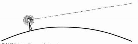
FIG. 15 The earth dropping away

FIG. 16 Sky wave

FIG. 17 Sky wave reaching more distant receivers
A number of things affect the distance radio waves can travel, so let's talk of what happens to them once they leave the transmitter. Each station, of course, has a lot of electronic gear which takes the sounds from the studios and converts them into the right types of electronic waves. Then somewhere, generally near the station, there is a transmitter and an antenna.
The transmitter sends the waves up the tower which then radiates them out into the air. Sophisticated antenna design can even determine what pattern these radiated waves take.
You might assume the pattern would have to be a circle around the antenna, as illustrated in FIG. 13. But that's not necessarily so. The pattern can be something like FIG. 14, if necessary. But once the waves leave the antenna, what hap pens to them? The earth drops out from under them. Really.
Those waves travel out from the antenna in a straight line, but the surface of the earth curves down and away. So the waves end up travelling right off the planet, as shown in FIG. 15.
That's why, when you get a certain distance away from a station, you can't hear it any longer. The waves are way up above you, heading out into space. However, that's not the whole story. The waves that do that are called ground waves because they travel along the ground, or close to it, before they become unreachable. But some waves leaving the antenna, also travelling in straight lines, hit that layer in the upper atmosphere called the ionosphere and bounce off it back toward the earth. Most of the waves go on through, but some don't.
Particularly at night some will bounce back to earth. The ionosphere gets closer to the earth and a bit more dense and hence throws a few more waves back. Those waves seem like they are coming out of the sky, and so they are called sky waves. Sky waves look something like FIG. 16. FIG. 17 shows what we get when we put these two waves together.
A sky wave covers a bigger area than a ground wave. Since sky waves work best at night, we are able to get many distant stations after the sun goes down.
RADIO RECEPTION
Because sky waves work best at night is also why you get two different types of coverage patterns for a station. That radiated pattern around the antenna is generally the pattern of the ground wave. The signal in there is fairly constant and fairly clear. Rain storms, tall buildings, and the like can cause some variations in the pattern, but it stays pretty much the same. It's this pattern the FCC has worked with for determining the frequency for a particular station. The Commission makes sure no other station on the same frequency exists within that pattern. That way, interference is minimized. But the sky waves give another, larger pattern in which that station can quite often be heard. The first pattern is called the primary coverage pat tern, and the one from the sky waves is called the secondary coverage pattern. The two are illustrated in FIG. 18.
The town of Medway is not in the primary coverage pattern of the station in Oak Bluff, but it is able to pick up the station most of the time. At night, the secondary pattern gets even bigger and includes Fairfield, which otherwise never hears the station.

FIG. 18 Coverage patterns from two separate towns

FIG. 19 Night coverage from Oak Bluff

FIG. 20 Night interference
But what about a station on the same frequency in Dewey? The primary pattern never touches Oak Bluff, so the stations don't interfere with one another. At night, though, the secondary patterns overlap in both Medway and Fairfield. People in those two towns get both stations at once, and the interference is so great they can't listen to either one. The FCC has tried to arrange frequency allocations so that happens as seldom as possible, but we all know there is a good deal of interference in AM. The Commission has even insisted there be at least 10,000 cycles between frequencies in an area. That is, a station broadcasting at 860 khz (kilohertz) will not have neighboring stations any closer than 850 and 870. However, stations still cross each other. Nothing's perfect.
The FCC has even set up a classification of stations in an attempt to keep the interference down. The classification works pretty well, if not perfectly. It runs like this. Class I stations can use from 10,000 to 50,000 watts of power and are on clear channels. That means very few other stations anywhere in the U.S. use the same frequency, and those that do are separated by hundreds and hundreds of miles. One is totally alone: WLW-AM in Cincinnati. It's the only station in the country on 700 khz.
Class II stations have power from 250 to 5,000 watts and are
also on clear channels. Very few others in the country share their frequencies. But they may have to be controlled in various ways so they don't interfere with Class I stations. Some go off at sunset and some have closely controlled radiation pat terms from their antennas. Class Ill stations have from 500 to 5,000 watts and are regional stations controlled so as not to interfere with clear channels. Others in the country may have their frequency too, but they are generally quite a distance away and only at night may some problems come up. Finally, there are the Class IV stations with no more than 1,000 watts during the day and 250 at night. Some even have to go off at night because so many surrounding stations share their frequencies. Interference is most common in this class. About half the stations in the U.S. fall into Class IV. FM has fewer interference problems because the signals just don't go out as far. There simply are no equivalents to the Class I 50,000 watt clear channel AM stations. So all FM stations are licensed to operate twenty-four hours a day and at full power for the entire time. That's not to say there is no concern over interference. Obviously, two stations on the same frequency still can't operate close to one another, but it's easier to keep them separated in FM than in AM.
--------------------
TABLE 3.1 Station classifications and their power ranges and characteristics.
Class Power ( Watts) Characteristics
I 10,000-50,000 clear channel
II 250-5,000 clear channel
III 500-5,000 regional
IV 1000 maximum day, local 250 maximum night
-------------------- FIG. 21 The mono signal plane

FIG. 22 The stereo signal planes
There's another aspect of FM broadcasting that's important to both stations and listeners. That's stereo, and in some cases, quad. You know that to get stereo sound from a record, you must have the right channel information on one side of the record groove and the left channel information on the other side. In FM broadcasting, you can get this same type of sides of-the-groove information by sending out your signal in a certain way. Think of the signal as going out all in one plane, as if all the bumps and changes and modulations of the waves were written on a flat sheet coming out from the antenna. That's like one side of a groove. Send out another batch of modified waves on a flat sheet that's perpendicular to the first, and you suddenly have two paths for information.
Your receiver at home can distinguish between these two sheets and so can send the right information to the right speaker, and the left to the left. Clever people, these engineers.
Next comes quad. Can you just add a couple more sheets? So far, no. The FCC hasn't approved that sort of thing because no one knows for sure what that sort of modification might do to coverage patterns, interference patterns, or frequency separations, and so on. So for radio, a quad set-up has been devised that superimposes two signals on one sheet and two on the other. Then, with the right gear at home, a listener can get the normal two sheets of information but break each sheet in two and thus get the four channels needed for quadraphonic sound.
The separation may not be as good as with four distinct, or discrete, channels, but it's good now and is getting better. This process is referred to as a matrix, or matrixed sound, because a matrix is a supporting structure giving form to something else. The final signal supports music in the form of quadraphonic sound.
The next time you listen to a stereo FM broadcast or a favorite AM station, think about that little box you call a radio.
It's picking up signals which pass right through solid walls and through you, for that matter. From all the signals around, it singles out the one you want and converts it into music or a human voice. Amazing!