Tape cartridges and reel-to-reel magnetic tape contribute a considerable share of modern broadcast schedules. The nature of the medium lends it self readily to automation in varying degrees. Fig. 5-1 illustrates program automation facilities including four reel-to-reel tape machines. Broadcast automation systems are covered in Section 7. We will consider only the individual reel-to-reel and cartridge tape systems in this Section.
5-1. REEL-TO-REEL MAGNETIC TAPE SYSTEMS
The magnetic tape head was basically covered in the preceding Section.
The basic parts of the transport system were shown in Fig. 4-25 in that Section.
The Tape Transport
Referring again to Fig. 4-25, note that the tape leaves the supply reel to pass over a tension arm to wrap around a stabilizing roller. This roller sometimes is attached to a flywheel to eliminate any tendency to flutter.
The tape then passes in contact with the erase, record/play, and simulplay (monitor) heads to the capstan and capstan pinch roller and then across the take-up tension arm to the take-up reel. If tape breakage should occur, either tension arm thus released stops the transport.
Some machines use individual and separate record and reproduce heads, with the reproduce head serving for monitoring during recording. Other (2-channel) equipment employs four heads: two-track erase, two-track record, quarter-track reproduce, and two-track reproduce. The two-track or quarter-track reproduce operation in this case is selected by positioning a switch on the head assembly. Some special-purpose reel-to-reel recorders such as those used for logging at a speed of 1 7/8 inches/second do not employ an erase head. The tape must be erased with a bulk eraser external to the machine.
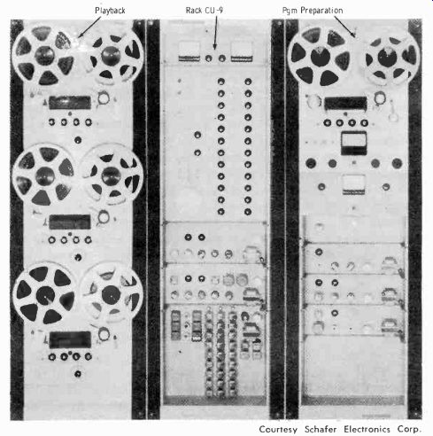
Fig. 5-1. Program automation equipment.
Three motors are normally employed in professional machines, two torque motors for the supply and take-up reels, and a multispeed hysteresis-synchronous motor for driving the capstan. In the record or reproduce mode, the pinch roller moves to engage the tape tightly against the rotating capstan shaft. This capstan and pinch roller combination exerts full control over the tape speed. The supply and take-up reel motors act only to maintain proper tape tension. The supply-reel motor actually applies a slight backward pull on the tape as it unwinds. The take-up reel motor applies sufficient forward torque to maintain correct tape tension on that side of the capstan assembly. Electromechanical brakes (usually mounted on the torque motors) stop the supply and take-up reels evenly to prevent "spilling" the tape.
Overall Electronics
Fig. 5-2 is a block diagram of a typical 2-speed magnetic tape system.
The most common speeds for normal use are 3 3/4 and 7 1/2 inches per second. The 7 1/2 and 15 in/s equipment normally is used only where a large amount of production requiring copies (dubs) is scheduled.
Record Path--The program input is fed through a record level control to an amplifier coupled to an emitter follower. The emitter follower is employed wherever high input and low output impedances are desirable.
Pre-equalization then occurs in series through selectable equalizers depending on the speed selected. Low input and output impedances are normally used for equalization circuitry, so another emitter-follower stage follows the equalizer. A constant-current amplifier (very high internal resistance) is used to drive the recording head through a bias filter. This filter prevents the bias current from interacting with the constant-current amplifier and vice versa. The bias oscillator also supplies the erase head for recording, and the bias magnitude to the record head is varied by means of an adjust able trimmer capacitor.
Reproduce Path--The reproduce head feeds an amplifier and an emitter follower. Post equalization normally provides parallel circuitry to the re produce channel. The VU meter can monitor either the reproduce level or the recording level at the point shown by means of the input-reproduce switch. The record calibrate control is normally a factory adjustment which can be checked periodically by the maintenance technician. This control is adjusted so that with normal sine-wave input level, the VU meter on the machine reads 0 VU when a vtvm measurement at the output terminals reads +4 dB. (Review Section 2-10, Section 2 ) .
The complementary-symmetry emitter follower used to drive the line output provides a low-impedance, single-ended push-pull output signal current with a high degree of linearity.
NOTE: Fig. 5-2 illustrates a system in which separate record and repro duce heads are employed. On machines where the same head is used for playback and for recording (record/play head) , the head is relay-switched between the record output and play (reproduce) input depending on the mode of operation selected.
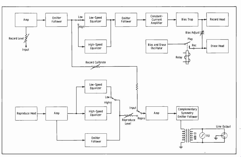
Fig. 5-2
Equalizers The need for equalization for a magnetic tape medium should be apparent after a review of Figs. 4-29 and 4-30 (Section 4) . Note that, for example, if the output level at 200 Hz is 0 dB, the output at 400 Hz will be about +6 dB. This is a rise of 6 dB per octave (each time the frequency is doubled, a change of one octave has occurred) . At low frequencies, there is a small rate of change across the gap; hence there is very low induced magnetic field energy. At higher frequencies, a greater rate of change occurs across a given gap size; hence there is more induced energy. At still higher frequencies, several additional factors appear. There is a loss in the tape from tape-coating thickness factor. Also, as the wavelength approaches the gap size, cancellation of energy begins to occur. At the high-frequency limitation, the response falls quite rapidly.
The recorded wavelength is:
Recorded wavelength =
Velocity Frequency The recorded wavelength for a 15-kHz tone at a tape speed of 7.5 in/s is:
Wavelength = 15,000-
0.0005 inch = 0.5 mil
If the magnetic tape head has a gap size of 0.2 mil, the 0.5 mil recorded wavelength is a little more than twice as long as the gap width. The ratio of wavelength to gap size must be at least two to one as a practical limit so that the output can be adequately pre-emphasized for good reproduction and signal-to-noise ratio. Losses in the magnetic core structure cause the signal to begin to decrease before this point.
To examine the low-frequency problem, look at the response curves of Figs. 4-29 and 4-30 in the reverse direction. If the response at 1000 Hz is +10 dB, the response one octave lower (500 Hz) will be +4 dB. Another octave lower (250 Hz) , the response is -2 dB. Still another octave lower (125 Hz), the response is-8 dB. The limit of how far down the response can go and still be usable is set by the residual noise level encountered in the tape, head, and machine electronics of any particular system as a whole.
Emitter Low Follower Speed 3.9 uF 18K 50-380 pF 20 pF
Speed 270K
0.1 Q2 Emitter to Next Follower Stage
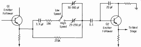
Fig. 5-3. Typical pre-equalization in two-speed tape system.
It is obvious that equalizers must be used to bring both the low- and high-frequency regions of the audio range (30-15,000 Hz) into line with the middle frequencies. In practice, this involves both pre-equalization (re cording mode) and post-equalization (reproduce mode) , as shown in Fig. 5-2. In addition, for multispeed transports, separate equalizers must be used for each speed employed.
Fig. 5-3 illustrates a typical pre-equalization network for a two-speed magnetic tape system running at either 3 3/4 or 7 1/2 in/s. The additional fixed equalization provided by the small capacitance between collector and base of Q2 is usually found in most recorders.
Fig. 5-4 shows typical circuitry for post-equalization. Note that the circuitry is identical for both speeds, but that the arrangement permits proper adjustment of equalization for either speed without the need of such critical adjustments each time the speed is changed. Resistors R3 and R4 provide high-frequency equalization, and R1 and R2 provide low-frequency equalization. This is a shunt type of circuit between the emitter of Q3 and the emitter of Q1 (low-impedance sources) .
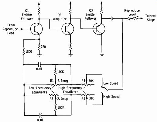
Fig. 5-4. Simplified diagram of typical post-equalization circuitry.
Fig. 5-5 presents the NAB (National Association of Broadcasters) standard pre- and post-equalization curves used by the broadcast industry. Note that pre-equalization provides boost at both the low and high ends of the frequency range and that post-equalization provides a complementary curve. The overall result is a practically flat frequency-response curve with maximum signal-to-noise ratio.
Record-Head Drivers
Fig. 5-6 illustrates a typical constant-current record-head amplifier of the type used in professional recorders. Transistor Q4 acts as a bootstrap on Q3. Over the audio range, the collector of Q3 works into an impedance value which is sufficiently high compared to the record head to provide constant-current characteristics.
The audio signal is fed to the record head through a bias trap. At the head, It is mixed with the bias frequency (normally 60 to 100 kHz) . The bias trap is simply a parallel tuned circuit which is resonant at the bias frequency. The values shown in Fig. 5-6 are for a bias frequency of 100 kHz.
The Erase and Bias Oscillator
A typical erase and bias oscillator is shown in Fig. 5-7. It is a conventional flip-flop working into a tuned circuit. Capacitor C1 across adjustable transformer T1 sets the frequency of oscillation. The activating dc voltage is applied only when the system is placed in the record mode. The bias symmetry control adjusts the current division between Q1 and Q2 so that a symmetrical waveform can be obtained.
The Erase and Bias Output Network
See Fig. 5-8. The network providing the feed to the erase and record heads must be well shielded, as are the heads themselves. Capacitor C1 al lows adjustment of the erase current to the erase head, which may require anywhere from about 125 to 325 milliamperes, depending on the construction. Similarly, R1 provides adjustment of the magnitude of the super sonic bias current to the record head. Construction of these heads varies widely, and the amount of bias current required is more accurately given in ampere-turns. The bias current varies in practice between different types of heads and may cover a range of 4 to 70 milliamperes.
NOTE: A special form of magnetic tape recording for adding reverberation (electronically) to live studio productions is described in Section 11.
5-2. THE SELF-CONTAINED TAPE CARTRIDGE SYSTEM
The tape cartridge is preloaded with magnetic tape for immediate re cording or playback. The compact cartridge slips into position in seconds, and no threading is involved. A typical cartridge employing a continuous loop of lubricated tape drawn from the center is shown in Fig. 5-9. As the tape is used, it is wound on the outer part of the loop. This loop principle does not require take-up or rewind motors; only the capstan motor and pinch miler are required for drive.
Two. general types of loops are used in the tape cartridge. These are the continuous loop in which the beginning and end are spliced together in a straightforward manner, and the mobius loop, in which a half-twist is imparted to the beginning of the tape before it is spliced to the end. The mobius loop permits dual half-track recording to double the recording time.
The tape made for continuous loops is lubricated on the backing side only. A mobius loop requires double-coated tape with lubrication on both sides and a Mylar base in the middle.
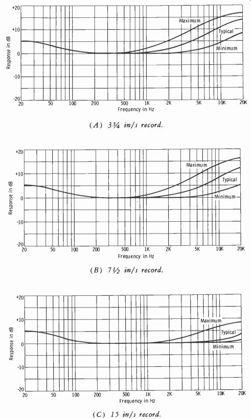
Fig. 5-5. Standard pre-equalization- and post-equalization curves.---(A)
3 3/4 in/s record. (B) 7 1/2 in/s record. (C) 15 in/s record. (D) 3 3/4 in/s
reproduce. (E) 71/2 in/s reproduce. (F) 15 in/s reproduce.
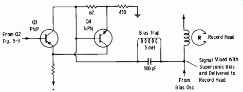
Fig. 5-6. Constant-current record-head amplifier. Signal Mixed With Supersonic
Bias and Delivered to Record Head
Erase heads are not normally used on the cartridge tape deck. The tape must be erased on an external bulk eraser.
When the cartridge is placed on the tape deck, a lever is moved to pivot the pressure (pinch) roller from below the deck position to hold the tape securely against the capstan. Pressure pads within the cartridge hold the tape flat and firmly against the record/play and cue heads.
Tape Cartridge Terminology
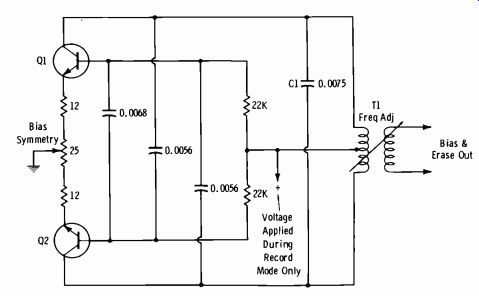
Fig. 5-7. Typical erase and bias oscillator.
Following is a tabulation of accepted terminology as applied to tape cartridge equipment:
Cue track: The lower track in a two-track cartridge monophonic system, and the lowest track in a three-track cartridge stereophonic system.
Program Track: The upper track in a two-track cartridge monophonic system, and the upper track (left channel) and middle track (right channel) in a three-track cartridge stereophonic system.
Head A: The magnetic (reproducing) head nearest the capstan.
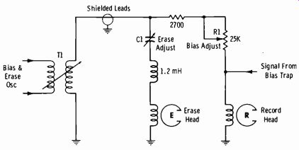
Fig. 5-8. Feeds to erase head and record head.
Head B: The magnetic (recording) head adjacent to head A.
Primary Cue Tone: A 1000-Hz tone recorded on the cue track and used for placing the tape in the cued position. The stop tone.
Secondary Cue Tone: A 150-Hz tone recorded on the cue track and used as the "end of message" signal. This tone is generally used for starting other equipment in an automation system.
Tertiary Cue Tone: An 8000-Hz tone recorded on the cue track and used as desired. This tone has been known in the past as an auxiliary or trip cue tone.
Cartridge Size A: The size A cartridge was previously known as Series 300, or the smallest size.
Cartridge Size B: The size B cartridge was previously known as Series 600.
Cartridge Size C: The size C cartridge was previously known as Series 1200.
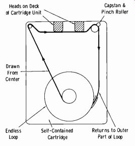
Fig. 5-9. Path of tape in endless-loop cartridge.
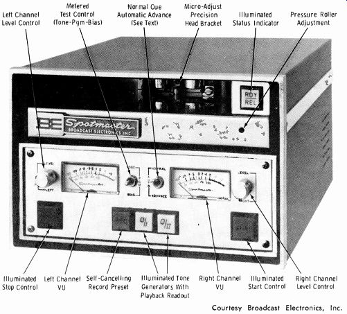
Fig. 5-10. Stereo tape cartridge record/play system.
--------------------
Metered Left Channel Test Control Level Control (Tone-Pgm-Bias) Normal Cue Automatic Advance I See Text) Micro-Adjust Precision Illuminated Pressure Roller Head Bracket Status Indicator Adjustment Illuminated Left Channel Self-Cancelling Illuminated Tone Right Channel Illuminated Right Channel Stop Control VU Record Preset Generators With VU Start Control Level Control Playback Readout
The tape speed is 7 1/2 inches per second. Spot announcements or pro gram material can be as short as one second or as long as 31 minutes.
When a recording is started, the 1000-Hz tone is automatically placed on the cue track. In many operations, the spot or program material simply plays through the capacity of the particular cartridge and is automatically stopped by the 1000-Hz tone and is then recued for another play. Thus the 1000-Hz tone is the primary cue tone which serves as the cued position, or stop position. If more than one spot or production is to be placed on one cartridge, the stop button is depressed after the first segment, and the additional recording is added so that the primary cue tone will again serve as the cued or stop position. Upon completion of the final segment, the tape is allowed to continue until stopped by the first primary cue tone.
Note from the list of terminology above that two additional tones are available. Sometimes it is desirable to insert secondary and tertiary cue tones after the message (s) has been completely recorded. This permits monitoring and accurate placement of the tones, especially where they are employed to start other equipment in an automation system.
Some tape cartridge equipment is arranged so that the record unit and playback unit comprise separate systems. In other equipment, both systems are housed in the same cover. Fig. 5-10 illustrates a stereo record/play unit with separate level controls for left and right channels. Note the cue switch (three position) marked Normal-Auto-Advance. The normal position al lows normal cueing as previously described. The automatic cue provides automatic end of message and rapid advance to the next segment on the tape. The advance position provides manual fast forward with automatic stop on the 1000-Hz primary tone.
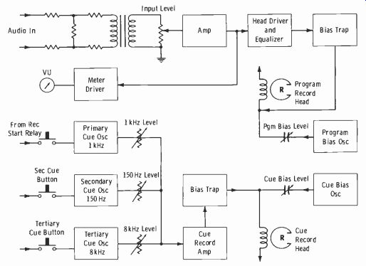
Fig. 5-11. Typical recording electronics of tape cartridge system.
Basic Electronics of Cartridge Tape Systems
Fig. 5-11 shows a simplified block diagram of the basic recording circuitry. The program recording circuitry is similar to that of conventional reel-to-reel magnetic recording, described previously. The basic additions are those associated with the cue-track recording head. When recording is started, the primary cue oscillator is automatically started by a momentary contact associated with the record relay. The secondary and tertiary cue oscillators (optional equipment) are activated by relays associated with their respective momentary-contact push buttons. The cue tones are mixed through individual level controls and fed (through a bias trap) to the cue record head, which also receives the cue bias frequency.
Fig. 5-12 is a block diagram of typical playback electronics for tape cartridge systems. The small signal output of the playback head is amplified and fed through a playback level control to the line output driver. The pickup from the cue playback head is amplified through a broadband amplifier and fed through a cue sensitivity control (level control) to individual (tuned) amplifiers, each of which activates a relay. The primary cue tone trips the machine to stop. The secondary and tertiary cue tones activate relays the normally open and/or normally closed contacts of which appear on a terminal board to be carried to any control point desired.
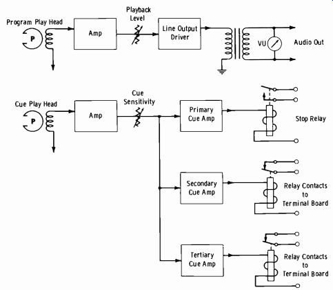
Fig. 5-12. Typical playback electronics in tape cartridge system.
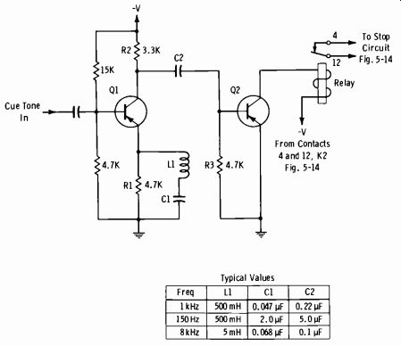
Fig. 5-13. Typical cue amplifier.
The Playback Cue Amplifier
The cue-tone oscillators in the recording unit are conventional LC stabilized oscillators working from a well regulated dc supply. The playback cue-tone amplifiers (Fig. 5-13) are sensitive only to their individual tone frequencies. In the quiescent state, Q1, since its emitter resistance (R1) is greater than its collector load resistance (R2) , is in a low-gain operation.
Also, Q2, since it has no forward bias in the quiescent state, is cut off. The combination of L1 and C1 forms a series-resonant circuit at the individual tone frequency. Thus, on the arrival of a tone that is at the frequency of resonance of the series-tuned emitter return, the emitter circuit of Q1 becomes a very low impedance to ground and allows the transistor stage to become a very-high-gain amplifier. The resulting large (negative) excursions coupled to the base of Q2 saturate that transistor so that the relay circuit is completed to ground and is thus activated, opening the normally closed contacts. After the short tone duration, Q2 again cuts off. The time constant of C2 and R3 is made long compared to one cycle of the tone frequency so that Q2 does not operate as a rapid switch during the individual cycles of the tone.
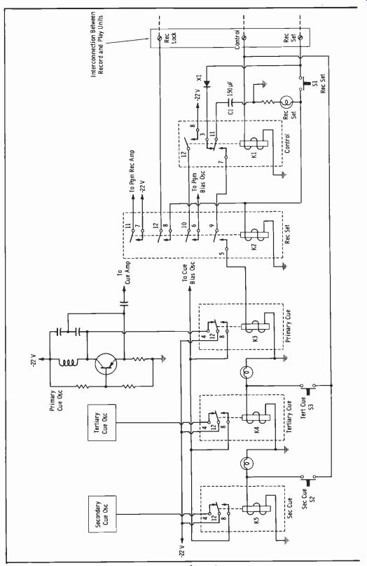
Fig. 5-14
Typical Control Circuitry
Fig. 5-14 will enable the reader to become familiar with the important basic control functions of a typical tape cartridge system. In this example, the record and play units are separated.
The playback-unit control functions will be examined first. When the main power on-off switch is closed, indicator lamp I1 (usually a neon lamp) indicates that primary power has been applied and the system is ready for use. When a tape cartridge has been placed in the holder properly, the stop lamp is illuminated through closed contacts 2 and 10 of relay K1. Stop switch S2 is a normally closed switch and is momentarily opened by pushing the switch. This switch is in series with contacts 4 and 12 of K3. Note also that when the cartridge is in place to operate switch S3, power is applied to the capstan motor. Thus the motor is running at constant speed before the capstan solenoid engages the pinch roller and tape.
When start switch S1 is depressed, dc is applied to the start lamp and relay K.1. This relay is latched on by contacts 9 and 5 (now closed) on K 1.
Contact pairs 8 and 12 and 7 and 11 energize the capstan solenoid, engaging the pinch roller with the tape to move it instantly at the proper speed.
The grounded swinger arm (10) is moved to contact 6, which causes the stop indicator to go off and completes the return for record set relay K2.
Therefore C1, which has charged through X1, is now able to discharge through K2 to operate that relay momentarily and open contacts 4 and 12 to prevent operation of K3.
Relay K3 is in the collector circuit of the primary cue amplifier (Fig. 5-13). Until this relay is operated by the primary cue tone (stop cue), contacts 4 and 12 of K3 are closed in series with the closed contacts of the stop switch, S2.
When the 1-kHz cue tone occurs, relay K3 is energized as described previously, opening contacts 4 and 12 of K3 and removing power from K1, thus stopping the transport. All contacts return to their previous state, and the stop lamp is again illuminated. Note that the action is the same as if the manual stop switch (S2) had been depressed.
We can now proceed to the record unit. When record set switch S1 is depressed, power is applied to the record set lamp and relay K2. This relay is latched on by contacts 8 and 12 of K2. Contacts 7 and 11 close to apply dc to the program record amplifier. Contacts 6 and 10 close, but the circuit is not completed until control relay K1 is energized. Similarly, contacts 5 and 9 close but without circuit completion for the same reason.
Note that in the present mode, capacitor C1 in the record unit is charged to the applied voltage through diode X1 and normally closed contacts 3 and 11 of control relay K1.
When the start button on the playback unit is depressed, the tape moves as described before, and control relay K1 in the record unit is energized by contacts 9 and 5 of K1 in the play unit. Capacitor C1 in the record unit discharges through contacts 7 and 11 of K1, contacts 9 and 5 of K2, and primary cue relay K3. This momentarily closes contacts 8 and 12 of K3 to apply dc to the cue bias oscillator and removes the primary cue oscillator inhibit voltage ( described below) by opening contacts 4 and 12.
All of the cue-tone oscillators work on the same principle as the automatic primary cue-tone oscillator shown in Fig. 5-14. When contacts 4 and 12 on K3 are closed, the collector of the oscillator is essentially returned to ground through the low internal impedance of the dc supply. When K3 operates, this ground is removed, and the cue tone is passed to the cue recording head simultaneously with the cue bias frequency. As soon as C1 is discharged, relay K3 again opens and the tone is removed. The secondary and tertiary cue oscillators (when used) are operated by momentary push buttons S2 and S3; this action also energizes the cue bias oscillator.
The unit will remain in the record mode until automatically stopped by the primary cue tone as described before for normal playback.
NOTE:
Special types of tape recorders (such as those used for artificial reverberation) as well as operating techniques for all tape systems are covered in Section 11. Maintenance procedures are outlined in Section 13.
EXERCISES
Q5-1 Do all tape recording systems employ an erase head?
Q5-2. On a reel-to-reel tape recorder, does the torque of the take-up reel motor have any control over the tape speed?
Q5-3. What governs the exact tape speed?
Q5-4. What are the two most common tape speeds for reel-to-reel tape systems employed in am-fm broadcasting?
Q5-5: Why must low-frequency equalization as well as high-frequency equalization be employed in a tape recorder?
Q5-6. What is the standard tape speed for the tape cartridge system?
Q5-7 In a tape cartridge system, give the standard frequency for:
(A) The primary cue tone.
(B) The secondary cue tone.
(C) The tertiary cue tone.
Q5-8. Where is the cue track on a cartridge tape?
Q5-9. Give the arrangement of program tracks on a stereo cartridge tape.
Q5-10. In a tape cartridge system, why is the capstan motor forced to run before the actual start of tape movement?