A transducer converts one type of power to another. A microphone converts alternate condensations and rarefactions of air (sound waves) into corresponding electrical variations. A phono pickup converts mechanical motion from recorded tracks on a record to corresponding electrical variations. A magnetic pickup head converts alternating magnetic fields on the tape to corresponding electrical variations. A loudspeaker converts electrical variations to a mechanical movement, causing corresponding air vibrations that can be detected by the ear.
4-1. THE MICROPHONE
In dealing with any mechanical or electrical component, there is always an "ideal" which the designer must use as a criterion of performance. An ideal microphone for most purposes should have an output voltage independent of frequency, and a uniform response for any one direction of a sound wave. In this ideal case, the instrument would deliver to the audio amplifier power whose frequency, phase, and amplitude components would be exactly the same as the original acoustical energy.
There are two basic types of microphones: the pressure type, and the pressure-gradient type. Pressure types, in turn, are quite varied, including carbon, condenser, crystal, moving-coil (dynamic) , etc. There is only one pressure-gradient instrument, the velocity type, incorporating a metallic ribbon suspended in a magnetic field.
Each different type of microphone exhibits a different response pattern (Fig. 4-1). The pattern simply represents the amplitude response for varying positions of the sound sources about the microphone. A nondirectional pattern is illustrated in Fig. 4-1A. If a constant-intensity sound source is moved around the microphone at a constant distance, the amplitude of the electrical impulses from the microphone will also remain constant. In Fig.
(A) Nondirectional. (B) Bidirectional (C) Unidirectional.

Fig. 4-1. Three fundamental microphone patterns.
4-1B, the response of the microphone decreases as the angle of the sound source approaches 90° from either face of the instrument. This microphone is sensitive from front and rear while theoretically "dead" at both sides, resulting in a bidirectional pattern. Still another fundamental type is illustrated in Fig. 4-1C; it is sensitive only to sounds originating in front of the microphone and is said to have a unidirectional response. Briefly, it may be stated that pressure microphones are nondirectional, velocity micro phones are bidirectional, and a combination of the two is unidirectional.
These response patterns are measured in an acoustically "dead" room.
The condition is equivalent to an open space where there is absolutely no reflection of sound waves. The effect of room acoustics on the action of the microphone will be discussed in Section 11. It will also be shown that response patterns vary somewhat for different frequencies.
Impedance Values and Cable Lengths
Just as there is a need for a wide variety of response patterns, there is also a need for a difference in the designs for permanent or portable use, and a number of impedance values for use in the complex fields of radio and sound.
The output of a microphone will either be high impedance working directly into the grid circuit of the input amplifier stage, or low impedance using a 30-, 150-, or 250-ohm transformer. This low impedance works into the input transformer of an amplifier. Some microphones built for various applications have a tapped output transformer with screwdriver-adjustable switch to select either high- or low-impedance output.
In general, high-impedance microphones are used for general communications, amateur radio, some pa installations, and some home recorders.
They are especially applicable if the length of the microphone cable is kept under 25 feet.
The effect of the length of a microphone cable is directly related to the impedance and the application of the sound system. The metallic shielding in a cable forms a capacitance with the inner conducting wires, and this is added to the capacitance between the wires themselves. The effect is equivalent to placing a capacitor across the line; the higher the impedance used the greater will be the shunting effect across the line with consequent loss of high-frequency response. Cable length, therefore, definitely must be considered when high-impedance microphones are used. The effect of any length of cable is negligible for low-impedance systems.
Fig. 4-2 shows the signal loss caused by extra cable length over 20 feet.
This is based on a good microphone cable with a low capacitance of 0.0007 µF per 20-foot length. For a cable length of 200 feet, the frequency response at 5000 Hz would be 15 dB lower than for a length of 20 feet.
Thus, broadcasting stations, recording studios, and special pa installations
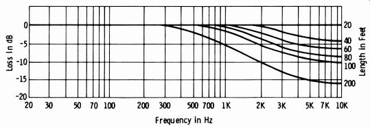
Fig. 4-2. Signal loss versus cable length (high-impedance input).
in which long cable lengths are a necessity always use low-impedance microphones. Low impedance must also be used in any form of communications where the operator works at a point remote from the microphone amplifier, since medium and high frequencies are important for crispness and intelligibility of speech.
Output and Noise Levels
Every electrical amplifier has a noise level that depends largely on the thermal noise generated in the input stage of the amplifier and which be comes larger as the bandwidth is increased. Thermal noise is generated in such microphones as the carbon and some condenser varieties where a voltage is applied to the microphone elements, but there is also noise in all other types due to certain fluctuations in the air pressure from thermal velocities of air molecules. Just as the noise level of a particular amplifier limits the lowest signal volume to be amplified, the thermal noise in the air places a lower limit on the atmosphere when used as a sound-energy medium. In fact, the noise component of air acting on the diaphragm of an extremely sensitive microphone is about equal to the thermal noise of a high-quality amplifier. This noise, however, is just about equal to the threshold of hearing of the most sensitive ears, between 1000 and 5000 Hz.
Should any microphone (other than a carbon type) noticeably raise the noise level at the output of a good amplifier, a fault within the microphone, cable, or input circuit is indicated (unless a stray ac field is being picked up).
High-impedance microphones and carbon microphones intended for general communications use have a somewhat higher output level than low-impedance units. The output levels of low-impedance microphones are always given as open-circuit or unloaded transformer input ratings. It is quite important in most low-impedance installations that the microphone be worked into an unloaded circuit. The response of ribbon and combination-type microphones may be seriously affected by a reflected resistance load on the mechanical constants of the moving elements. Fig. 4-3 shows typical microphone input circuits. The input is said to be "unloaded" since, although the transformer primary matches the microphone impedance at a given frequency (usually 400 Hz) , no loading resistance is used.
(A) Transistor amplifier. (B) Vacuum-tube circuit.
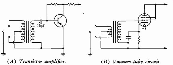
Fig. 4-3. Microphone input circuits.
Sound & Diaphragm
(A) Action under excessive pressure. (B) Action with normal loading.
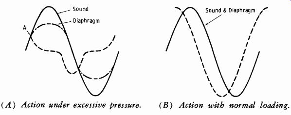
Fig. 4-4. Movement of diaphragm in dynamic microphone.
Volume-Handling Capability
Another limiting factor of a microphone is the maximum sound pressure that can be handled without distortion. This is particularly true of pressure type units. It is the function of the diaphragm, which is connected to the moving element inside, to move physically in accordance with the applied sound pressure, thus providing a voltage image of the sound. There is, however, an elastic limit to this movement. Suppose that the diaphragm is connected to a moving coil as in the inductor (or dynamic) microphone.
Fig. 4-4A shows what happens when an extremely loud sound pressure, such as shouting, occurs close to the unit. At point A, the sound is still in creasing, but the elastic limit of the diaphragm has been reached, and it has come to rest. This means that the coil has also come to rest, and the voltage output has dropped to zero, even though the air pressure is still increasing on the diaphragm. The diaphragm then returns at high velocity as the pressure subsides, and a surge in voltage is created; the distortion is shown by the dashed voltage line. This kind of waveshape results in blasting and contains a number of distortion components and false harmonics. Fig. 4-4B shows how the voltage is generated in a normal microphone that is not overloaded; the voltage follows the shape of the sound pressure exactly.
The Pressure Microphone
The pressure microphone, known variously as the moving-conductor, inductor, and dynamic microphone, is one of the most popular types in all fields of radio and sound. The electrical output results from the motion of a conductor (usually a small coil) in a magnetic field. The magnets are of the permanent type and require no external voltage.
There is actually a slight technical difference between a moving-coil microphone and an inductor type, although the operating principles are identical. The moving-coil type, as its name implies, utilizes a small coil in the magnetic field. In the inductor type, the diaphragm actuates a straight conductor that is suspended between the magnets.
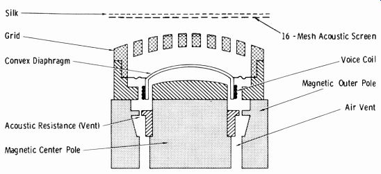
Fig. 4-5. Basic diagram of moving-coil microphone.
Fig. 4-5 shows the basic construction of a moving-coil unit. Motion of the diaphragm causes the small coil to move back and forth in the magnetic field in accordance with the actuating sound pressures. In practice, the small voltage thus generated is applied across a transformer, the primary of which matches the impedance of the coil. A varying audio voltage appears across the secondary of the transformer; this secondary has an impedance of 50, 150, or 250 ohms or high impedance depending on the application desired.
The mass resistance on the opposite end from the coil is used to balance the movement of the diaphragm.
Without a sort of resistance control or damping, however, a diaphragm and coil assembly of this kind would have a frequency response somewhat similar to that of curve A in Fig. 4-6. Curve B is the idealized response curve of a microphone and indicates the necessity for some kind of resistance control.
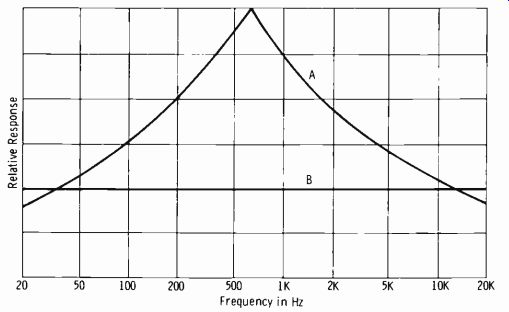
Fig. 4-6. Dynamic-microphone response curves.
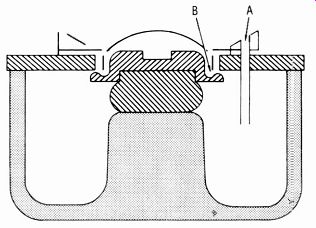
Fig. 4-7. Means of damping (A) and compensation for mass reactance (B) at
high frequencies.
Damping is accomplished in several ways. Fig. 4-7 shows an assembly with a tube (A) and an air slit (B) . Air slits overcome the mass reactance of the diaphragm at high frequencies high-frequency response) resulting in an increase of over an octave at the high end of the scale. An increase in low-frequency response is obtained by the action of the tube and its associated air cavity. The addition of these features is de signed to maintain uniform diaphragm velocities at all frequencies.
Most coils used in dynamic microphones are wound with aluminum ribbon or wire; aluminum provides a maximum ratio of conductivity to mass. When ribbon is used, it is wound edgewise on the form. Diaphragms of the dynamic and inductor types are made of either aluminum alloys, styrol, Bakelite, or paper.
The Pressure-Gradient Microphone
The pressure-gradient, velocity, or (more commonly) ribbon microphone employs the moving-conductor principle in which a ribbon is suspended so that it vibrates freely in a magnetic field. This ribbon constitutes its own diaphragm; since it is not housed in any closed type of case and is exposed to the air on its two active sides, there are no adverse effects of cavity resonance, diaphragm resonance, or pressure doubling.
Fig. 4-8 illustrates the basic construction of a ribbon microphone. The ribbon is made of a thin corrugated aluminum strip (aluminum alloy to minimize mass) and is suspended between the poles of a permanent mag net as shown. Movement of the ribbon caused by passing sound waves causes the magnetic lines of force to be cut transversely, inducing a corresponding voltage between the two ends of the ribbon. In order that the ribbon constitute a mass reactance over the usable range, its resonant frequency is made lower than the lowest frequency to be reproduced. This eliminates peaks.
The ribbon moves through the magnetic field in the direction of diminishing pressure as a function of the difference in sound pressure between the front and back of the ribbon. Thus, under certain conditions, it is said to correspond in motion to the particle velocity in a sound wave, hence the term velocity microphone. This rate of pressure change with distance is called pressure gradient.
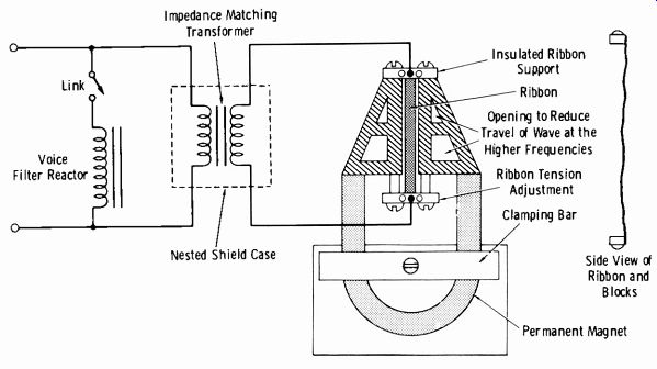
Fig. 4-8. Fundamental construction of ribbon microphone.
The ribbon can respond only along the axis perpendicular to its surface and is "live" to sound waves only from either face; it is "dead" from the side (90° from the zero axis). Hence, this microphone is, by the nature of its design and construction, a bidirectional instrument.
It should be understood that although the pressure of a sound wave in air may be independent of frequency, the pressure gradient, or rate of pres sure change with distance, is not. Therefore, the mechanical impedance of a ribbon is proportional to the frequency of the actuating sound waves. In practice, this is only important where the spherical character of low-frequency speech waves very close to the mouth will cause a greater pressure on the ribbon than the higher-frequency components of speech. Thus, when a person speaks into a ribbon microphone at close range, there is a definite "boominess" resulting from an accentuation of the lower frequencies. This is overcome by use of a speech trap when the microphone is to be used for speech only. It consists of an adjustable tap on the output transformer which raises the impedance of the ribbon from its extremely low value to 50, 150, or 250 ohms, and lowers the open-circuit reactance of the transformer such that low-frequency response is decreased. The tap is adjustable by means of a slotted switch on the bottom of the microphone case and is usually marked "music" and "voice."
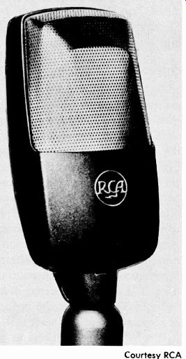
Fig. 4-9. RCA SK-46 velocity microphone. Courtesy RCA
A typical ribbon microphone, the RCA Model SK-46, is illustrated in Fig. 4-9. It is a later version and is less than half the size of the earlier RCA Model 44-BX. Actually, there are two models of this later version, the SK-35 and the SK-46. They are similar except for the close-talking feature of the SK-35. This unit is particularly suited for remote broadcasts in factories, busy offices, or other noisy locations. The lips of the speaker should be less than one inch from the front screen of the SK-35 in this application.
The SK-46 is also used in studio applications, where it is especially suitable for across-the-table discussions. The frequency-response curves for the rib bon microphones discussed are shown in Fig. 4-10.
Patterns of Response
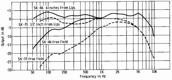
Fig. 4-10. Frequency response of SK-35 and SK-46 microphones.
(A) Sound from front.
(B) Sound from rear.
(C) Sound from side.
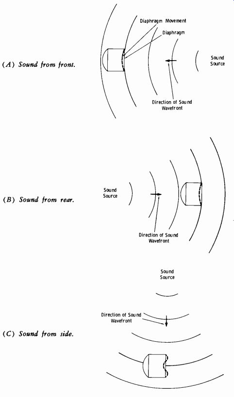
Fig. 4-11. Action of pressure microphone.
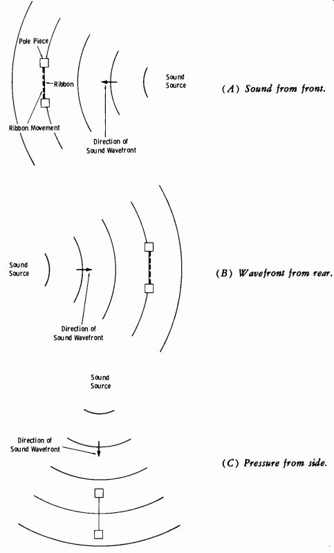
Fig.
4-12. Action of ribbon microphone. (A) Sound from front. (B) Wavefront from
rear. (C) Pressure from side.
Fig. 4-11 illustrates the diaphragm of a pressure-type microphone being excited by sound waves. In Fig. 4-11A, the sound originates in front of the instrument; as the wavefront passes, the diaphragm is brought from rest to the position shown by the dashed line. This results from the pressure of the condensed air and is the principle of a pressure-type microphone. In Fig. 4-11B, the sound is coming from the back of the microphone, but the pressure of the wavefront causes the diaphragm to move inward just as before. In Fig. 4-11C, the sound originates at the side, and the point of sound pressure causes the diaphragm to move inward once again. Hence, it may be seen that the diaphragm always moves in the same direction regardless of the initial direction of the traveling wavefront, resulting in a nondirectional response pattern. This type of microphone can be made semidirectional by orientation of the case and by the use of baffles. How ever, it is not a truly directional microphone as are other types.
Fig. 4-12 illustrates the action in a velocity microphone when the ribbon is actuated by sound waves. Waves on either face of the instrument (0° or 180°) cause the ribbon to move, although in opposite directions, for a given wavefront. Sound coming from the side (90° to axis of face) cause equal and opposing pressures on the sides of the ribbon, resulting in a theoretically zero movement of the ribbon. Hence, the microphone has essentially a "figure eight," or bidirectional, response.
The unidirectional microphone is just what its name implies: an instrument that by design is live on only one face, and dead toward the sides and rear. It is useful in broadcasting and recording studios. The unidirectional pattern may be obtained in a number of ways. The first method used was the combination pressure and pressure-gradient principle that is still widely employed. Primarily, it consists of a pressure element, usually a moving coil, and a ribbon element connected in series. They are phased so that the outputs of the separate elements reinforce each other for sound coming from a given direction relative to the face of the instrument, and they can cel each other for sounds coming from the sides and rear. This will be clarified by the following brief review of pressure and pressure-gradient element action.
Look again at Fig. 4-11A and compare it with Fig. 4-12A, noting that the diaphragm and its associated coil assembly and the ribbon in the velocity microphone respond in the same direction to the traveling wavefront.
Therefore, if these two elements were connected in series and properly phased, the output of the microphone would be large in amplitude with sound from this direction. Now compare Fig. 4-11B and 4-12B. The pres sure element moves in the same direction as before, whereas the ribbon element moves in the opposite direction. With the same wire connections as before, the voltage generated by the ribbon will oppose that of the moving coil. It is obvious, then, that sound emanating from this direction will be effectively canceled out at the microphone transformer, resulting in zero response. Sound from the side will result in zero response from the ribbon element, but will still actuate (to a modified extent) the pressure element.
This is why the typical unidirectional microphone has a much wider angle of pickup to the front compared with the velocity (bidirectional) micro phone.
Effect of Angle on Frequency Response
In the hypothetical instance of the "ideal" microphone case mentioned earlier, the instrument should be uniformly directional at all frequencies;
however, such is not true in practice. High frequencies travel in a relative beam-like configuration compared to the low frequencies, and a number of design and construction compromises must be made. The use of a non directional microphone, for example, oriented so as to become semidirectional is possible only for the higher frequencies which are sufficiently deflected by the dimensions of the case. At lower frequencies, approximately 1000 Hz or less, the microphone is nondirectional in any position.
Such an orientation is useful in reducing high-frequency feedback in public-address installations associated with broadcasts which require a non directional microphone.
It is well known that high-frequency response falls off with increasing angles from the zero axis, or from a line drawn through the exact center of the diaphragm. Whenever the wavelength of a sound wave is short compared to the width of the diaphragm, several points of unequal pressure exist which cause an irregular movement. Thus, it becomes obvious that for best high-frequency pickup at increasing angles to the face, the diaphragm must be smaller than the wavelength of the highest frequency considered. In practice, this is impractical due to the extremely low output that would be obtained from such an instrument, and a compromise must be made. It will be noted, therefore, that all microphones are directional at high frequencies and have wider angles of equal response areas at the middle and lower frequencies. A typical frequency-directivity response pattern is shown in Fig. 4-13.
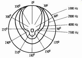
Fig. 4-13. Frequency dependence of directivity.
The Unidirectional Microphone The feature of directivity is a useful characteristic for discriminating between wanted and unwanted sound. The applications are endless. Public address engineers must guard against feedback. The communications engineer is interested, generally, only in a voice immediately at one side of the instrument; the same is true for the amateur operator. Recording and broadcasting technicians are concerned with the same general principles of wanted and unwanted sounds, and all shades in between for proper balance of various sources.
The first approach to achieving a truly directional instrument was the combination pressure and pressure-gradient principle. This effectively nulls one loop of a bidirectional pattern, making the microphone sensitive only to sounds from one side. Since the ribbon element is the most practical for a pressure-gradient microphone, and the moving-coil or dynamic principle has proven highly effective (due to light weight and freedom from temperature effects) for the pressure microphone, these elements were used in the unidirectional instrument.
A simple connection of the two elements in series is only the beginning, however, of obtaining a practical unidirectional response. This is because the magnitude of response for a given sound pressure and the phase of the output voltage differ over the usable frequency range, particularly at low and high frequencies. Thus, certain deviations in design and construction from the conventional ribbon and dynamic units are apparent in the micro phone.
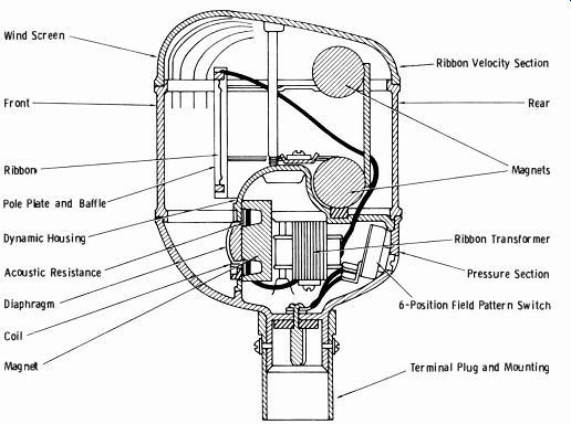
Fig. 4-14. Construction of cardioid microphone.
---- Wind Screen Front Ribbon Pole Plate and Baffle Dynamic Housing Acoustic Resistance Diaphragm Coil Ribbon Velocity Section Ribbon Transformer Pressure Section 6-Position Field Pattern Switch Terminal Plug and Mounting
First, the diaphragm of the dynamic unit must be as close as possible to the ribbon in order to minimize phase difference. At the same time, there must be no disturbance of normal operation due to the proximity of the units. Thus, the housing of the dynamic unit must be streamlined to have minimum effect on the close ribbon element; and the ribbon assembly must be designed with a wider-than-normal air gap requiring heavier permanent magnets.
Second, since the two elements have essentially the same magnitude and phase response at middle frequencies but may deviate considerably at low and high frequencies, an electrical equalization or corrective network must be used in the outputs of the two elements before their combination at the output transformer.
The Western Electric 639B cardioid microphone (Fig. 4-14) was a typical combination ribbon and dynamic instrument. The ribbon element in this microphone was redesigned to meet the above requirements and also to reduce flutter caused by wind when used outdoors. This ribbon is about half the length of a normal ribbon, somewhat narrower, but greater in thickness. This thickness results in a stiffness about ten times that normally employed in a velocity microphone with greater stability and consequent reduction of noise caused by wind.
The lower part of the microphone case contains the dynamic unit and housing, in which is located the ribbon transformer, electrical equalizer, and variable pattern switch. This switch permits use of the microphone either as a dynamic unit alone, ribbon unit alone, or both in series to achieve the unidirectional response pattern. With the switch in the D (dynamic) position, the response is nondirectional. In the R (ribbon) position, the ribbon is used alone, and the usual bidirectional pattern is obtained. To obtain the cardioid or unidirectional response, the switch is turned to the C position, which utilizes both elements through the electrical equalization circuit.
There are several more modern means of constructing a microphone with unidirectional response other than the combination ribbon and moving-coil system just described. Their basic action, however, is based on the same general principles.
Fig. 4-15 illustrates a method in which a ribbon element, such as commonly employed in velocity microphones, acts as a pressure-operated de vice. It is suspended in the usual fashion in the magnetic field of a permanent magnet, but differs from the velocity type in that the face is exposed to the atmosphere whereas the rear side is terminated in an acoustic resistance. Thus the back of the element is enclosed so that it presents an infinite impedance to sound, resulting in a microphone that is pressure-operated with nondirectional characteristics, except at high frequencies.
Ribbon Felt Several Coils Felt
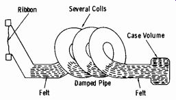
Fig. 4-15. Infinite impedance for producing unidirectional characteristics.
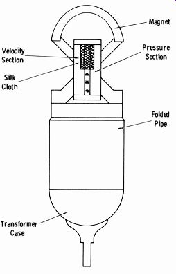
Fig. 4-16. Unidirectional microphone.
By combining this principle with that of the pressure-gradient ribbon action, a unidirectional response pattern is obtained. Fig. 4-16 illustrates this method, where one continuous ribbon is used, with the upper half acting as a velocity (pressure-gradient) microphone and the lower half acting as a ribbon pressure device terminated in the rear with a folded pipe ( the acoustic resistance). The pipe is usually damped with tufts of felt.
Due to the length of pipe behind the pressure section, the velocity of the pressure ribbon leads the pressure in the sound waves at the low audio frequencies. To compensate for this characteristic, a cloth screen is placed in front of the velocity section to introduce a corresponding phase shift in the velocity ribbon. Phase shift at high frequencies is minimized by using the same ribbon element for both units and suitable geometrical configurations of the field structure.
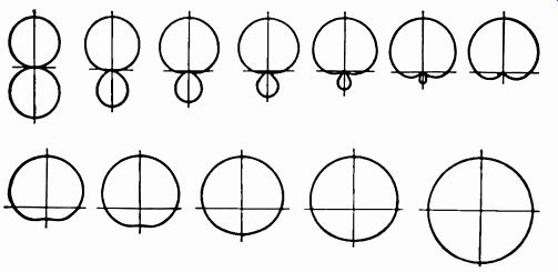
Fig. 4-17. Directional patterns produced by altering area of damping-tube
opening.
The design of the RCA Type 77-D microphone is somewhat similar to the principle described with an added means of varying the acoustic impedance presented to the ribbon. A switch varies the area of an adjustable opening in the labyrinth connector. When the opening is so large that the back of the ribbon is entirely exposed to the air (as in the ordinary velocity microphone) , the acoustic impedance is zero, and the response pattern is bidirectional. When this aperture is completely closed, the acoustic impedance is infinite, and the microphone becomes nondirectional in the manner of the usual pressure-operated device. By varying the size of the opening, a great variety of response patterns can be obtained. Fig. 4-17 shows typical patterns ranging from bidirectional to nondirectional.
A more recent RCA development is the BK-5A Uniaxial microphone, illustrated in Fig. 4-18. The term Uniaxial is derived from the fact that the direction of maximum sensitivity coincides with the major axis of the unit.
The directional properties in the mid-frequency region are essentially cardioid with an 18-dB front-to-back ratio (Fig. 4-19). The high-frequency directional properties have been improved over the Type 77-D, both in pickup angle and in front-to-back ratio. The pattern of the BK-5A is not adjustable.
As described, the Type 77-D employs one (adjustable) port at the back of the ribbon, which in combination with the acoustic labyrinth controls the directional properties. In the Type BK-5A there are two ports, one placed at each end of the ribbon. The ports are covered with an acoustically controlled cloth to form the proper opening impedance. The movable element is a ribbon with a horn and screen assembly in front and the acoustic connector and labyrinth behind. The port impedance and the acoustic resistance of the labyrinth along with the physical separation of the front and rear pickup points give this unit its unidirectional characteristic. The acoustic labyrinth is a pipe about 31 inches long folded into the form of a cylinder. It is damped along its length to eliminate resonances and acts as a pure acoustic resistance over a substantial part of the frequency range.
The electrical circuit consists of the corrugated aluminum-foil ribbon, a line-matching transformer (brought to a terminal board for adjustment to 30-, 150-, or 250-ohm circuits), and a response-compensation reactor. A switch incorporated with this reactor allows selection of three response characteristics, music (M) , voice 1 (V1), and voice 2 (V2) (Fig. 4-20) .
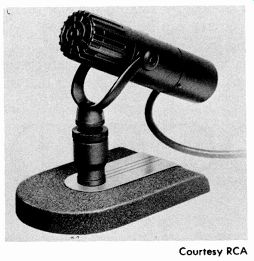
Fig. 4-18. RCA BK-5A microphone. Courtesy RCA
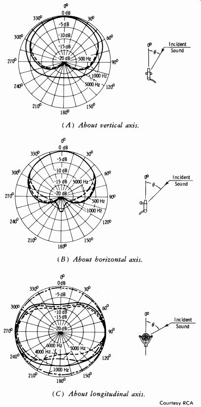
Fig. 4-19. Directional characteristics of BK-5A microphone. (A) About vertical
axis. (B) About horizontal axis. (C) About longitudinal axis.
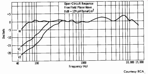
Fig. 4-20. Effect on frequency response of BK-5A music/voice switch.
4-2. THE TURNTABLE AND PICKUP
The broadcast turntable (Fig. 4-21) is designed to handle all commercial disc recordings. A preamplifier for the pickup cartridge is usually mounted within the turntable housing. Although designs vary, the following list outlines a typical turntable facility:
1. Drive Mechanism: Usually a capstan-to-idler rim drive or a belt drive, powered by a 1/100-horsepower 1800-rpm synchronous motor (or a 4-pole motor) with a three-step pulley ( for three speeds) coupled to the motor shaft.
2. Controls A. Speed Selector Switch: A three-position control linked to a cam which allows the three rubber idlers to engage, one at a time, be tween the motor pulley and the turntable rim. The speed of the turntable is determined by the ratio of diameters between the motor pulley and the turntable rim.
B. Off-On Switch: Usually operates a mercury switch (for quiet operation) which energizes the motor and simultaneously engages or disengages the rubber idlers.
C. Equalizer: A circuit which is usually incorporated in the preamplifier with a switch shaft extending through the turntable mounting board for convenience. Terminology varies considerably, but the following results are achieved:
(1) Normal: Provides standard NAB/RIAA equalization. (Recordings are pre-emphasized with complementary de-emphasis on playback to achieve a higher over-all signal/noise ratio.)
(2) Plus Highs: Results in greater high-frequency response (less de-emphasis) for use where some of the high-frequency response has been lost due to wear, but signal/noise ratio is still good.
(3) Minus Highs: Less high-frequency response for elimination of higher-frequency noise where required.
---------------
Turntable Cartridge & Balancing Assembly Stylus Assembly 45 Indicator Speed Control Light Panel Pivot Tone Cartridge Arm Holder Moto On-Off Motor On-Off Arm Light Switch Rest 33 Indicator Light Courtesy Broadcast Electronics, Inc.
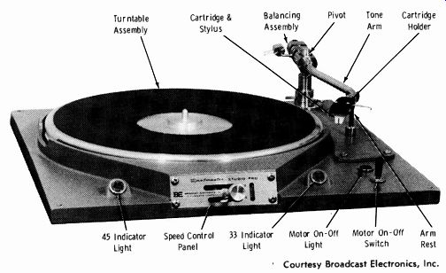
Fig. 4-21. Broadcast turntable.
-----------------
The turntable preamplifier and equalizer are more fully described in Section 6.
The most important characteristics of the turntable and pickup along with the associated preamplifier are wow, flutter, hum, rumble, and frequency response. The use of test records and general maintenance procedures are included in Section 13.
How the Pickup Cartridge Works
One of the most popular types of pickups used in broadcasting today is the variable reluctance pickup. When the signal recorded in the lateral variations of the record grooves vibrates the stylus from side to side, cur rents are set up in the magnetic poles. This generates an electrical signal which corresponds to the signal which originally caused the lateral groove variations of the recording. The stylus is mounted so that it is insensitive to vertical variations, isolated from external mechanical vibration, and subject to a minimum of surface noise.
Either a 2.5- or 3-mil stylus (1 mil = 1/1000 inch) is used for 78-rpm discs; a 1-mil stylus is required for microgroove (33 1/3 rpm) recordings.
Some units employ plug-in cartridges that can be easily removed and replaced.
The Stereo Disc and Pickup
Stereo is covered later in this guide. Suffice it to say here that two separate signals and amplifying channels are required, one each for the left and right listening areas.
The modern stereo system, including stereo disc recording, is compatible.
This means that the stereo recording can be played back in a conventional monaural manner as well as providing two channels for stereo systems.
The two channels are provided in a single groove on the stereophonic disc recording. The basic concept of stereo disc recording is illustrated in highly simplified form in Fig. 4-22.
The recording process is represented in Fig. 4-22A. The left and right pickup area signals are fed to their respective cutting-stylus drive coils.
These coils are arranged to provide modulation axes in quadrature to each other and at 45° angles relative to the record surface. Fig. 4-22C shows the groove resulting from a signal applied only to the right (1) or left (2) coil. Note in each case that a vertical component results which identifies the difference between channels. If identical signals are applied to both channels in phase (3) , a lateral groove with no difference component results.
If identical signals are applied to both channels with a 180° phase difference, only vertical (difference) modulation results (4 in Fig. 4-22C) .
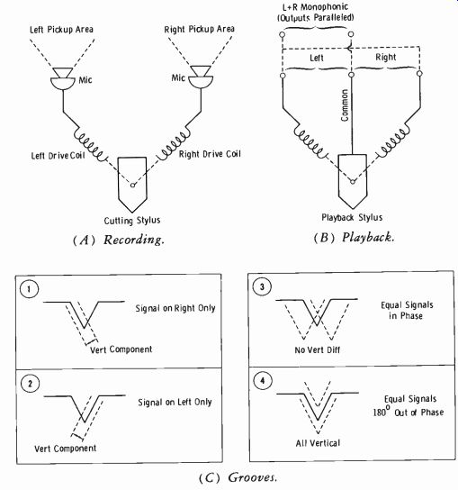
Fig. 4-22. Principles of stereo disc recording. (A) Recording. (B) Playback.
(C) Grooves.
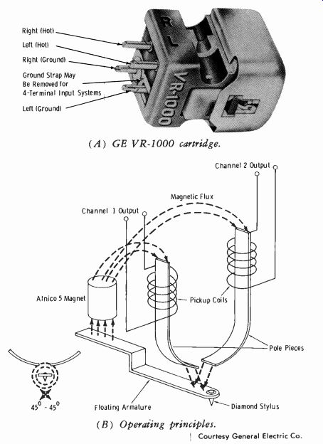
Fig. 4-23. Stereo pickup cartridge.---- (A) GE VR-1000 cartridge. (B) Operating
principles. Courtesy General Electric Co.
In essence, this is a lateral recording of the sum of the left and right signals, and a vertical recording of the difference between the channels.
The stereo playback cartridge (Fig. 4-23A) has a single stylus and three terminals, left, right, and common. For a stereo system, the left and common terminals feed the equalizer for the left channel, and the right and common terminals feed the equalizer for the right, channel. The left and right terminals can be paralleled to feed a single monophonic channel.
Also, the lateral grooves make the disc compatible for a conventional monophonic pickup cartridge, since this represents the sum (L-- R) signal, which is essentially what any monophonic system reproduces. A word of caution: Just any monophonic pickup is not suitable for playing a stereo recording on a monophonic system. The cartridge must have good vertical compliance to avoid damage to the disc and to track the vertical modulation without causing distortion in the signal.
Fig. 4-23A illustrates the GE stereo variable-reluctance cartridge, type VR-1000. The principle of operation is shown in Fig. 4-23B. A linear relationship between stylus motion and output voltage is achieved by placing the magnet over the end of the floating armature, thereby magnetically saturating the special iron. The armature design causes a circular magnetic field to envelop the stylus gem. These circular lines of force surrounding the stylus move with the stylus as it traces the recorded groove. A lateral motion of the stylus varies the proportion of flux between the two pole pieces. A vertical motion of the stylus varies the total flux in the magnetic circuit. Thus the motion of the stylus by the recorded grooves is translated into left-channel and right-channel outputs in accordance to the original recording.
The stereo pickup stylus has a diameter of 0.7 or 0.5 mil, contrasted to the 1-mil stylus used for monophonic recordings. Some systems employ readily replaceable plug-in cartridges for stereo, microgroove, and 78-rpm discs.
The Quadraphonic (4-Channel) Disc
Quadraphonic (4-channel) systems are fully discussed in Section 7. At this time, we are concerned only with the nature of the disc and the stylus action involved.
At the time of this writing, the entire status of quad sound is in a state of flux. There are two basic systems involved, the matrixing technique and the discrete system. The matrixing system has various names: the SQ system (CBS) , the QS system (Sansui) , and the Stereo-4 system (Electro-Voice ).
The matrixing system essentially mixes four separate channels into a composite that is recorded on the disc. It is encoded into a stereo fm transmitter. A decoder at the receiver separates the four channels to be reproduced by four speakers. The same program can be reproduced on standard mono or stereo receivers, just as color television signals can be received in black and white on monochrome receivers.
In the quad technique, the four reproducers are basically located left-front and right-front, left-rear and right-rear. Briefly, the matrixed quad disc has left-front and right-front channels recorded in the two side walls of the grooves along the 45° lines as in normal stereo records. In addition, a helical groove cut is imposed by circular motion of the cutting stylus, clockwise for the left-rear modulation and counterclockwise for the right-rear modulation. In playback, the stylus does not actually rotate clockwise or counterclockwise; the single stylus motion is a complex function that reproduces the four individual signals that can be decoded and separated into the four separate speaker feeds. (Encoding and decoding are covered in Section 7.) The discrete disc employs a 30- to 40-kHz subcarrier that tells the play back cartridge which speaker the sound should go to at any instant. Again, the two groove walls at 45° angles to the vertical (90° to each other) carry the conventional stereo signal information. In addition, a difference signal is added to the sum signal in each groove wall. These difference signals are frequency and phase modulated on the subcarrier. The demodulator at the receiver sorts the sum and difference signals into the proper four amplifier channels.
4-3. THE MAGNETIC TAPE HEAD
The complete magnetic tape system is covered in Section 5. We are concerned at this time with the head and its associated components.
A magnetic field is created when an electric current passes through a conductor. When a magnetizable substance is brought within this field, the small atomic regions or domains of the material become oriented so that their axes are aligned with the field of force about the conductor, and the material exhibits a magnetic field of its own. When the current is stopped or the magnetized substance is withdrawn from the field, the material retains a magnetic force to an extent depending on the remanence of the material.
In magnetic tape recording, actual steel is no longer used as the magnetic substance. Instead, a magnetic coating is placed on a plastic base that is one-quarter inch wide (for most audio applications) and about two thousandths of an inch thick. The actual coating is about half a thousandth of an inch deep.
Fig. 4-24A illustrates the basic action of a magnetic tape system. As the signal is fed into the recorder head, the tape passes at a constant speed across the very small gap of the recorder head core. This gap is usually 0.001 to 0.002 inch, but may be as small as 0.00005 inch (0.05 mil) . Thus at any given instant, a tiny magnet of this dimension is formed, and the recorded signal consists of a string of these minute longitudinal magnets whose flux and polarity correspond to the signal current in the head at the instant each magnet was formed.
The magnetic properties of a signal recorded on magnetic tape may be illustrated as shown in Fig. 4-24B. The sound track here has been made visible by means of a method that is similar to the mapping of fields about a bar magnet by using iron filings. In this instance, the recorded tape was passed through a suspension of carbonyl iron in heptane. Carbonyl iron consists of particles much smaller than ordinary iron filings. It may be observed by this illustration that the tape actually consists of a string of magnetic fields which correspond to the amplitude variations of the original signal that was recorded.
Basic Principles
Fig. 4-25 shows the usual mechanical arrangement of a tape recorder.
This is known as the capstan drive system and is used in all tape recorders where reliable and flutter-free operation is mandatory. The capstan is driven by the drive motor and is weighted with a flywheel to assure speed regulation. The tape is held firmly against the capstan by the pressure roller and tension. The supply reel containing the tape is at the left; it is actuated by the rewind motor to rewind the tape after recording. The tape is threaded across the erase, record, and playback heads, around the capstan, and onto the take-up reel. This reel is driven by the forward, or take-up, motor. The speed of rotation may be adjusted either by variable speed motors or by varying the size of the capstan. The tape transport is more fully described in Section 5.
(A) Magnetizing action of recording head.
Magnetic Coating 5 "n"s"H"5- . w`-5 Tape Travel--5-
Courtesy Ampex Corp.
(B) Word "tape" recorded at 30 in/ s, full track.
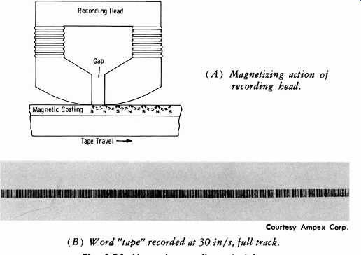
Fig. 4-24. Magnetic recording principles.
The wavelength of the recorded signal for a given frequency depends on tape speed. For a 15,000-Hz tone on a tape moving at 15 inches per second, one full wavelength is 0.001 inch. On playback, if the head gap is equal to the recorded wavelength, there is complete cancellation of the magnetic field. The gap should be no more than one-half the wavelength of the highest frequency to be recorded, or in this case 0.0005 inch. For a gap of 0.001 inch, it would be necessary to run the tape at 30 inches per second to cover a frequency range up to 15,000 Hz (so that the recorded wave length at this frequency would be 0.002 inch) .
Note: Pressure pads are not used in many late model recorders.
The head assembly is moved downward by a solenoid to make contact with the tape during recording or playback.
In fast wind or rewind, the head assembly is moved upward away from the tape, as in the stop position.
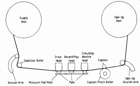
Fig. 4-25. Basic parts of reel-to-reel magnetic tape recorder.
The Necessity for Bias Remember from magnetic theory that the extent of magnetization depends on the strength of the magnetic field. Thus, the amount of magnetism retained depends on the magnitude of the original magnetic field for a substance of given remanence ( ability to retain magnetic force).
Fig. 4-26 shows a graph of the amount of remanence versus the strength of the signal field. This curve may be compared in effect to the plate cur rent of a vacuum tube as plotted against grid voltage. It is obvious that the straight portions of the curve which would result in an undistorted signal output are very small. Fig. 4-27 shows the type of magnetic characteristic curve necessary for undistorted output.
Since there is no practical straight portion of a magnetization curve such as the one in Fig. 4-26, dc bias is out of the question when using a tape of zero magnetization as the operating axis. To overcome this difficulty, a high-frequency bias is used. Since this bias current is far above the highest audible frequency to be used, it is called supersonic bias. This voltage is not modulated by the signal current, but rather they are mixed together to form the pattern shown in the illustration.
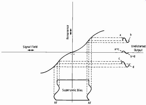
Fig. 4-26. Remanence versus signal strength for magnetic tape coatings.
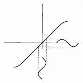
Fig. 4-27. Linear (ideal) remanence curve.
The audio component on the plus side of the zero magnetization axis results in the distorted output waveform shown in the upper portion of Fig. 4-26, where the a loop is larger than the b loop. The audio component on the minus side results in the lower distorted waveform, where the c loop is smaller than the d loop. Since these complete loops are combined on the axis of operation, the resulting output signal is undistorted as shown. That is, the algebraic sum of a plus c equals the algebraic sum of b plus d when the bias is of the proper magnitude for a particular recording head and magnetic tape.
The exact frequency of the bias does not seem to be critical, as long as it is high enough not to beat with the harmonics of the audio signal or subcarriers (such as fm stereo) . In practice, it is customary to make the bias frequency five times the highest audio frequency to be reproduced plus 5 kHz. Thus, a tape recorder with a frequency range up to 5000 Hz would use a bias frequency of five times 5, or 25 kHz, plus 5, equaling 30 kHz. A recorder system utilizing the full range up to 15,000 Hz would, therefore, require a bias frequency of at least 80 kHz. Commercial tape recorders utilize bias frequencies ranging from 30 to 100 kHz. Higher bias frequencies seem to give better signal-to-noise ratio on the average than lower bias frequencies, and most manufacturers are now using the high frequencies even for home-type recorders.
Effect of Bias Magnitude
Bias magnitude, or amount of bias used (measured by bias-current readings or ampere-turns of bias), is an important characteristic of magnetic recording. Too little bias results in high noise and distortion levels. Too much bias results in loss of high frequencies. In practice, however, bias is adjusted for minimum noise and distortion. Any resultant loss of highs is compensated for by increasing the tape speed or by equalization procedures.
The 3M Company, one of the leading researchers in magnetic-tape characteristics, has conducted exhaustive tests on the effects of bias with its particular sound tapes. As a basis from which to start, tests were run first on the effect of bias current on the output that could be obtained with no more than 1 percent third-harmonic distortion. Measurement of the third-harmonic distortion was chosen in preference to total distortion, since the total measurement would be affected by noise level. Measuring the third-harmonic distortion theoretically relates the measurement only to the magnetic properties of the medium. Even-harmonic distortion has been found to be negligible when using magnetically neutral tape (ac neutralized tape instead of dc-biased or saturated tape) with a supersonic bias of good waveform.
The curves of Fig. 4-28 show the results of the manufacturer's tests on the effect of bias. The actual number of bias ampere-turns is dependent on the particular recording head used, but the effects of changes of bias are substantially the same with any head. (Ampere-turns are the product of the current through the coil in amperes times the number of turns.) The optimum bias in this test for No. 111 sound tape results from 2.4 ampere turns.
The effects of bias on frequency response are shown in Fig. 4-29. It is seen that raising the bias results in severe loss of high-frequency response (probably due to a partial erasing action of the stray bias field) . The re cording, of course, is unequalized.
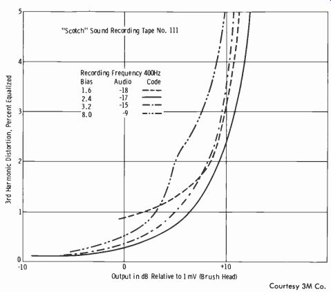
Fig. 4-28. Effect of bias on distortion.
It may also be observed from the above studies that using the optimum value of bias to obtain maximum output at no more than 1 percent third-harmonic distortion results also in the best high-frequency response relative to low frequencies. It is also known, however, that the noise level may be decreased by using higher values of bias, resulting in a somewhat better signal-to-noise ratio. The final design must be a compromise for the particular purpose of the recorder, and, as mentioned before, high frequencies may be brought up if necessary by using appropriate equalization, by using very small air gaps in the recording head, or by increasing the speed of the tape movement.
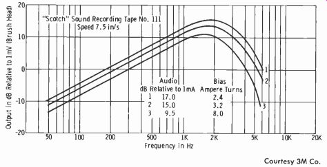
Fig. 4-29. Effect of bias on frequency response.
Effect of Tape Speed
The effect of speed on the recorded wavelength and consequent high-frequency response has been mentioned. The influence of recording-head gap size was also shown, and these factors should be kept clearly in mind for a comprehensive picture of magnetic recording.
Fig. 4-30 shows the effect of speed when the optimum value of bias is used. It may be observed that the highest speed of 18 inches per second results in best high-frequency response. The "high speed" has now been standardized at 15 inches per second.
Frequency response is dependent on several factors other than those mentioned. These may be enumerated briefly as follows:
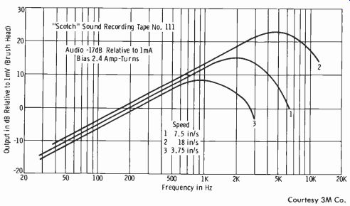
Fig. 4-30. Effect of tape speed on frequency response.
1. The design of the recording head
2. Recording-gap size
3. Reproducing head
4. Tape characteristics
5. Azimuthal orientation of heads
6. Characteristics of associated amplifiers
7. Tape contact against pole pieces
Importance of Tape Contact
In magnetic tape recorders, it is very important that the tape be held firmly against the smooth surface of the pole pieces and across the gap.
The effect of poor contact between the tape and the playback pole pieces becomes increasingly noticeable at higher frequencies. Fig. 4-3IA shows the attenuation caused by various separations of tape and playback head.
In these tests, a tape was recorded with various pure tones and then reproduced on a good system with proper contact. Then this tape was reproduced several times with paper shims of different thicknesses used to separate the tape and pole pieces by known amounts. The level was then recorded for each frequency and separation and compared with the original levels.
The separation values are given in mils. Data on the frequency scale are plotted for a tape speed of 7.5 in/s, but it will be remembered from the previous discussion that the wavelength effect is the important characteristic. In other words, for a given separation, the same attenuation will result at 5000 Hz (7.5 in/s), at 10,000 Hz (15 in/s), at 2500 Hz (3.75 in/s), etc. For this reason, the wavelength scale is shown at the top of the graph and is more significant, being true for any tape speed.
(A) Function of frequency for various separations.
Ratio of Separation to Wavelength
(B) Universal curve for any speed, frequency, and separation.
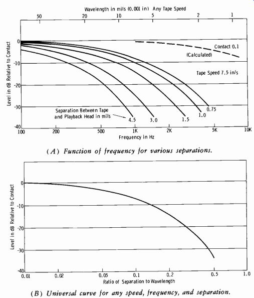
Fig. 4-31. Attenuation effect of distance between tape and playback head.
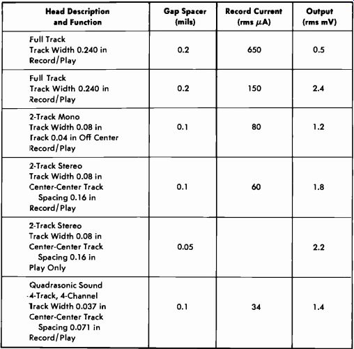
Table 4-1. Typical Magnetic Tape-Head Specifications
----------
NOTE: Above characteristics are an average employing 3M tape and 1-kHz tone recorded 12 dB below tape saturation.
Fundamentally, attenuation depends on the ratio of the separation to the wavelength. The same attenuation results from a 10-mil wavelength and 1-mil separation as for a 45-mil wavelength and 4.5-mil separation. Thus, Fig. 4-31B shows the amount of attenuation against the ratio of separation to wavelength.
It is evident from these results that very small separations can cause serious trouble in attaining comparatively good high-frequency response.
The pole pieces must be clean, smooth, and well machined. The tape must be smooth and flexible, with adequate tension or pressure. Plastic-base tape is superior to a similar paper-base tape; in addition, the noise level is somewhat lower. Later tapes use a polyester or acetate backing.
Table 4-1 lists typical magnetic tape-head specifications. Note from the top two listings (full-track standard record/play heads) that a broad variation in efficiency can exist between different types or makes of heads.
EXERCISES
Q4-1. Can a nondirectional microphone be made directional by "aiming" it toward the desired source?
Q4-2. What is the "normal" response (pattern) of an unmodified pressure-gradient microphone?
Q4-3. How many terminals are there on the normal stereo phono pickup, and how are they used?
Q4-4. Can a stereo phono pickup be used in regular mono broadcasting?
Q4-5. Does a phono pickup for quadra-sonic sound employ a single or multiple stylus?
Q4-6. How wide is the normal audio tape?
Q4-7. What is the normal track width recorded on a magnetic tape employing full-track recording?
Q4-8. What is the normal track width recorded on each track of a 2-track stereo tape, and what is the center-to-center track spacing?
Q4-9. What is the track width on a 4-track, 4-channel quadrasonic tape head, and what is the center-to-center track spacing?
Q4-10. Why is ultrasonic bias used in a magnetic tape head?