Broadcast programs are as varied as the interests of the more than twelve million people who make up the listening audience. It is inevitable that a great number of programs must originate at some point other than in a carefully designed studio that has a permanent and complex control con sole and amplifier racks.
Many stations today are investing a considerable sum in specialized re mote facilities. A complete two-turntable control console which collapses into a suitcase and is easily transported by one man is available. Such a facility is adaptable to remotes staged in automobile salesrooms, super markets, shopping centers, etc.-- wherever special promotional broadcasts are originated. Some stations own and operate complete mobile studios wherein a special truck or van houses the mobile equipment. Modern radio is witnessing a significant growth in remote and mobile service. The application of transistors to compact remote-control gear allows an adequate amount of facilities to be housed in quite small spaces.
Equipment used for remote broadcasts must provide the same means of mixing the outputs of the microphones and sufficient amplifier gain for the use of low-output, high-quality microphones as does the main studio equipment. It is obvious, however, that the equipment must be conveniently portable and, therefore, limited in size and weight. For this reason, many of the earlier types of remote amplifiers used low-level mixing circuits requiring only one preamplifier tube for all microphone inputs. Recent advances in circuit design, however, have permitted the use of high-level mixing circuits with all their advantages, without adding to the bulk of the equipment. Power is supplied by batteries or from the power line. In case of power-line failure, or in mobile applications, dynamotor supplies or batteries are used.
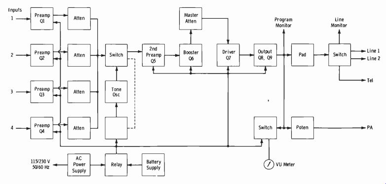
Fig. 8-1.
8-1. BASIC REMOTE MIXER–AMPLIFIERS
A typical transistor remote amplifier is the Collins 212Z-1, which provides for four microphones with high-level mixing. It weighs 22 pounds, including the batteries. This unit includes a power source for both 115 volts ac and batteries, with automatic changeover when the ac power fails and when it is restored; the self-contained batteries have a life of approximately 75 hours. The unit has a maximum gain of 90 dB, a tone oscillator for line-level setup, an auxiliary output for public-address feed, and step faders.
One or two headsets may be plugged into the monitor jacks. Where speaker monitoring or feed for local pa is desired, the pa terminals are used, and an individual gain control allows the operator to handle the pro gram and simultaneously ride gain on the pa system. A multiple jack is located on the side of the unit, permitting two units to be used simultaneously while being controlled by one master gain control.
Fig. 8-1 shows a block diagram of this remote unit. The four preamplifiers, Q1 through Q4, use 2N106 hermetically sealed low-noise transistors.
The input faders feed second preamplifier Q5 (also a 2N106) through the tone-oscillator switch. Booster Q6 feeds the master gain control, which is followed by driver Q7.
The booster and the driver both employ 2N64 transistors. The output amplifier has push-pull 2N44 transistors, Q8 and Q9, with transformer coupling on the input and output sides. The output transformer feeds the program monitor, VU meter, public-address line, and program switch.
Provision is made for two program lines and telephones through the output switch. The power supply is a shielded, filtered full-wave circuit employing germanium diodes and multisection filtering. A relay connects the batteries to the amplifier whenever the ac line voltage fails.
The 400-Hz oscillator employs a Colpitts circuit and feeds a low-level signal to the second preamplifier through a selector switch. A power inter lock switch insures that there is no battery drain when the unit is in its closed carrying case.
The four-channel mixing circuit incorporated in the amplifier is de signed to work with all microphones from 30 to 600 ohms. The output circuit is designed to match a 600-ohm line. To work into 150 ohms, the use of an external repeat coil is recommended. Minor rework of the unit will also provide a 150-ohm output. When a telephone set is connected to the TEL posts, the line can be used for communication with the master control room.
Although simultaneous program feed and communication cannot take place over a single line, the output switch allows rapid interchange between the telephone set for communication and the amplifier output for program transmission. This facilitates operation where only one line is available to the control point or radio transmitter.
When two lines to the master control are available, one can be used for program feed or receipt of cue preceding transmission, and the other can be used for simultaneous communication. With this arrangement, the communication line can be substituted for broadcast immediately by simply turning the output switch and making a corresponding switch in the master control room.
Fig. 8-2 shows the block diagram of another transistor portable remote amplifier, the RCA BN-6A. The VU meter monitors either the output level or battery current. The line-monitor output is a phone-type jack for head phones or speaker. Normally the signal from the studio is strong enough that the CUE-Mic 1 switch may be left in the normal Mic-1 operating position as shown. If the cue-back from the studio is weak due to long-line effects or other reasons, this switch may be turned to the Cue position. The signal will then be amplified through the amplifier to the headphones so that the cue may be heard easily. This is a spring-return switch so that the normal Mic-1 position is restored on release of the switch.
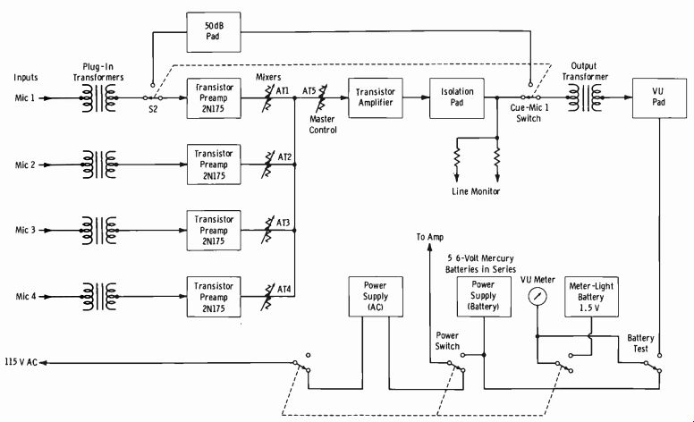
Fig. 8-2
---------------

Chart 8-1. Frequencies Allocated for Remote-Pickup Broadcast Base and Mobile
Stations 450.05* 450.15* 450.25* 450.35* 450.45*
' 152.87
' 152.93
' 152.99
' 153.05
' 153.11
Group K (MHz)
153.17
153.23
' 153.29
' 153.35 Group L
Group M (MHz) (MHz) 4 166.25* 4 170.15* Group N (MHz) 450.55* 450.65* 450.75* 450.85* 450.95* 455.05" 455.15* 455.25* 455.35* 455.45* 5 161.64* 5 161.67* 5 161.70* 5 161.73* 5 161.76* 455.55* 455.65* 455.75* 455.85* 455.95* Puerto Rico and Virgin Islands Only:
(MHz) (MHz) (MHz) 160.89 161.07 161.25 160.95 161.13 161.31 161.01 161.19 161.37 NOTE: These frequencies are shared with the Land Transportation Radio Service.
*Frequencies indicated by asterisk are exclusive to radio broadcast except as noted:
3 Subject to the condition that no harmful interference is caused to stations operating in accordance with the Table of Frequency Allocations.
4 Operation on the frequencies 166.25 MHz and 170.15 MHz is not authorized (i) within the area bounded on the west by the Mississippi River, on the north by the parallel of latitude 37°30' N, and on the east and south by that arc of the circle with center at Springfield, Ill., and radius equal to the airline distance between Springfield, Ill., and Montgomery, Alabama, subtended between the foregoing west and north boundries; (ii) within 150 miles of New York City; and (iii) in Alaska or outside the continental United States; and is subject to the condition that no harmful interference is caused to government radio stations in the band 162-174 MHz.
5. These frequencies may not be used by remote pickup stations in Puerto Rico or the Virgin Islands. In other areas, certain existing stations in the Public Safety and Land Transportation Radio Services have been permitted to continue operation on these frequencies on condition that no harmful interference is caused to remote pickup broadcast stations.
-----------------
8-2. MOBILE EQUIPMENT
Remote-pickup mobile and base-station equipment is licensed under Part 74, Subpart D, of the FCC Rules and Regulations, for the express purpose of broadcasting program material from a remote point outside of the studio location. Such a system may be licensed by the Commission for this purpose whether telephone land lines are or are not available. Chart 8-1 gives the frequencies allocated to remote-pickup broadcast base and mobile stations.
CAUTION: Always check current FCC Rules and Regulations.
Mobile Studio Facilities The Traveler, complete mobile studio facilities of radio station WXLW, Indianapolis, Indiana, is shown in Fig. 8-3. It is housed in a custom-built trailer which is 47 feet long and 8 feet wide and weighs 9 tons net. It is equipped with electric brakes, oil heat, air conditioning, water tanks, and leveling jacks. It has double-paned windows, and each pane is 1 inch thick.
Concealed fuel tanks supply the heating system and the stove, which is located in the combination lounge and kitchen (Fig. 8-4A) at the forward end of the trailer. The exterior skin of the trailer is aluminum. The interior is finished in acoustical tile on the ceilings and walnut plywood on the side-walls. The floors are carpeted.
Fig. 8-4B shows the studio and its equipment. In the center is the operating console, with a remote-control unit for the Ampex tape recorder located in the control room. Also mounted in the console are controls for the two turntables, a VU meter, a control for the air monitor, and a potentiometer for the news "beeper." The two turntables are equipped with transistor preamplifiers and a cue amplifier. A cabinet for the storage of tapes and discs can be seen between the console desk and lounge chair.
The control room is located approximately in the center of the trailer.
Some of the control-room equipment is shown in Fig. 8-5A. A Gates con sole is mounted beneath the studio window. Beneath the desk in the farthest left rack are a patch panel, AM air monitor, monitor amplifier, con sole power supply, and the switch and fuse panel. The second rack houses an RCA transistor tape recorder, a communications receiver for the 166-MHz link, and a 55-watt power amplifier for the outside speakers.
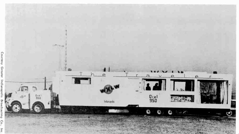
Fig. 8-3. Mobile studio facility designed to provide broadcasting of main-studio
quality.
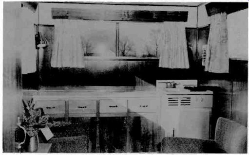
Fig. 8-4. Interior views of lounge and studio. (A) Combination living room,
lounge, and kitchen. (B) Studio with operating console and turntables. Courtesy
Greater Indianapolis Broadcasting Co., Inc.
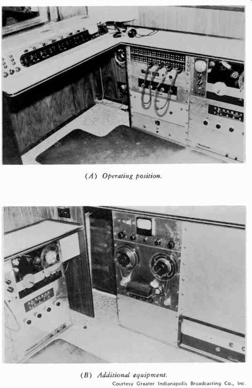
Fig. 8-5. Interior views of mobile control room.
----
(A) Operating position. (B) Additional equipment. Courtesy Greater Indianapolis Broadcasting Co,, Inc.
Fig. 8-5B shows the remaining control-room equipment. The main tape transport and its record/playback amplifier are mounted in the third rack, beneath the control-room counter at the rear. A 15-watt transmitter provides the main 455.55-MHz link to the home studio; it can be seen in the right rack in Fig. 8-5B. This device, with the yagi transmitting antenna (12.2-dB gain) on its 50-foot crank-up tower and the receiving antenna at the main studio (7.5-dB gain), provides a range of 25 miles while maintaining a program-quality signal.
The tractor was custom modified from a two-ton truck. The frame of the truck was shortened, a shorter drive shaft was installed, and the drive wheel's were moved forward so that the overall trailer-truck length could be within the 60-foot limit. A specially built housing on the truck accepts a 15-kW generator and also provides storage space for cables and power accessories. A waterproof nylon cover encloses the rear of the truck.
This elaborate setup is an example of the steps radio stations have taken to increase their program capabilities through remote broadcasting. This mobile unit provides full studio facilities and is completely independent of power and telephone lines.
Typical Mobile Equipment
Fig. 8-6A is a basic block diagram of the mobile broadcast technique.
Either vertical or horizontal polarization may be used.
Recent revisions to the Rules and Regulations permit the use of unattended, automatic relay of remote-pickup signals, to extend the coverage of remote-pickup broadcasting. This is particularly advantageous to those stations in mountainous areas or any location where it is difficult to cover a primary service area because of terrain conditions. A block diagram of an automatic relay system appears in Fig. 8-6B.
More recent rules permit the use of low-power devices such as walkie talkies, wireless microphones ( described in Section 8-3) , or any hand-held, portable transmitter to initiate the program material and broadcast it back to the mobile unit or remote transmitter for relay to the studio location.
This is becoming particularly important in extensive news operations for adequate coverage of events such as disasters and certain sporting events where it is practical to use such devices.
(A) Block diagram, basic installation.
(B) Use of automatic relay station.
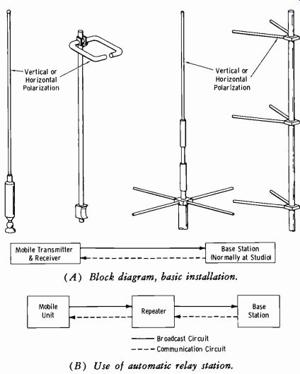
Fig. 8-6. Mobile broadcast technique.
Remote-pickup equipment can also serve the very important function of a back-up, emergency program link between studio and transmitter in the event of a loss of the program line, since the equipment is capable of broadcast sound quality and continuous-duty operation.
Station WIRE operates a fleet of mobile units employing Marti Electronics transmitter/receivers licensed for two frequencies 60 kHz apart in the 150-MHz region. A base transmitter and receiver are used for each channel, and the mobile units are each switchable to either channel. Separate horizontal and vertical antenna polarization is employed at the base station. Mobile units normally stay switched to the cue channel for cues and intercommunication, then switch to the on-air channel when called upon to broadcast.
Fig. 8-7 shows a view of the Marti RPT-40 all solid-state remote-pickup transmitter. This unit may be obtained to operate in either the 150- or 450-MHz band. The R-30/150 receiver is identical in appearance to the STL receiver described in Section 8-5. The RPT-40 has a 40-watt output in the 150 MHz band, whereas the RPT-25 has a 25-watt output in the 450-MHz band. These two transmitters are identical in appearance.
As shown by the block diagram of Fig. 8-8, two separate crystal oscillators generate the two operating frequencies, selectable by a switch. The switch is followed by the phase modulator, which accepts the audio input, normally from a compressor or limiter amplifier. This is followed by a series of frequency multipliers to raise the original crystal frequency to the desired operating frequency. In Marti equipment, this multiplication is 36 times for the 150-MHz band and 108 times for the 450-MHz band.
The frequency deviation accomplished by the phase modulator is also increased by the same magnitude as the operating carrier frequency. The final frequency swing is about plus and minus 7.5 kHz. A driver stage is then used to excite the final power amplifier, which drives the antenna through harmonic filters and contacts of the transmit-receive relay. It should be noted that the multiplier and remaining stages are sufficiently broad in response that no retuning is required for the two assigned operating frequencies. The maximum difference in frequencies is about 120 kHz.
Courtesy Marti Electronics, Inc.
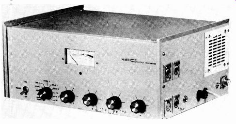
Fig. 8-7. Marti RPT-40 remote-pickup transmitter.
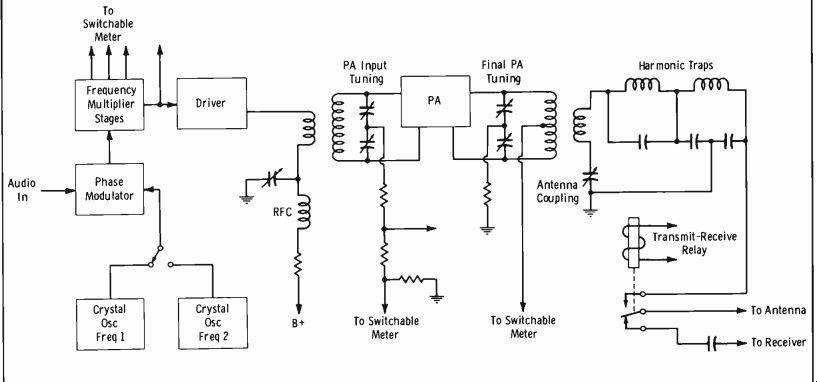
Fig. 8-8
It is usual in remote-pickup transmitters that only one meter is used to measure various operating parameters including stage-by-stage tuning of the rf section. The meter is normally arranged to measure the input drive current resulting from tuning of the previous stage. Thus each stage is tuned to result in a maximum reading on the meter. However, in Fig. 8-8, note that for the final-stage tuning the meter is placed in series with the rf tank current feed so that this output tuning is adjusted for minimum meter reading. Then the antenna coupling capacitor is adjusted also to obtain a minimum final input-current reading, and the two tuning procedures are repeated until exact resonance is obtained. The final adjustment for the antenna coupling capacitor is to obtain the manufacturer's recommended power input to the final stage. This is normally specified as a given current reading on the meter when monitoring the input to the final output tank circuit.
Fig. 8-9 illustrates how a typical Marti transmitter is installed in an automobile. Table 8-1 gives expected coverage for the conditions and types of antennas listed. This assumes flat terrain and a 30-watt transmitter in the 150-MHz band. Mobile applications in practice will be discussed in Section 12.
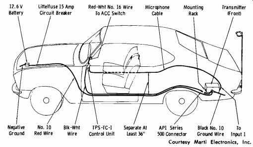
Fig. 8-9. Automotive installation of Marti remote-pickup transmitters. Courtesy
Marti Electronics, Inc.
8-3. PORTABLE TRANSMITTERS AND WIRELESS MICROPHONES
Small portable transmitters and wireless microphones are often employed in conjunction with the mobile relay transmitter. Fig. 8-10 shows the fundamental layout of equipment used to broadcast special events involving mobile relay service. Fig. 8-11 illustrates a transistor pocket fm transmitter with a push-to-talk switch and an internal microphone. The unit is battery powered and operates in the 132-174 MHz range.
Miniature transmitters of this type are normally good for line of sight only. Therefore the signals are often picked up on a receiver in the mobile truck, and the receiver output modulates the main mobile transmitter.
Mobile transmitters with their associated antennas are mounted in trucks or cars, variously known as "news-mobiles" or "mobile units." These units are also employed to keep in constant touch with the base station (often in the news room) so that when local news breaks it can be covered immediately.
------------

Table 8-1. Average Coverage Over Flat Terrain (30-Watt Transmitter, 152-172
MHz Frequency Band)
Receiving Antenna Height (Feet) Antenna Combinations Coverage (Miles) Receiving Transmitting
* 75 5-Element Yagi Single Ring 9
** 150 5-Element Yagi Single Ring 13
* 75 Stacked 5-Element Yagis Single Ring 11
** 150 Stacked 5-Element Yagis Single Ring 15
* 75 5-Element Yagi 5-Element Yagi 14
** 150 5-Element Yagi 5-Element Yagi 18
* 75 Stacked 5-Element Yagis 5-Element Yagi 16
** 150 Stacked 5-Element Yagis 5-Element Yagi 20
** 150 RA-4 Antenna Single Ring 10
***300 RA-4 Antenna Single Ring 14
** 150 RA-4 Antenna 5-Element Yagi 16
***300 RA-4 Antenna 5-Element Yagi 20 Code:
* Measurement based on length of RG-8U transmission line not to exceed 80 feet.
** Measurement based on length of 1/2" FHJ4 transmission line not to exceed 200 feet.
***Measurement based on length of 7/e" FHJ5 transmission line not to exceed 350 feet.
Notes:
The above measurements are based on a transmitting antenna height of 6 feet above surrounding objects. An increase in height of the transmitting antenna to 30 feet will increase the coverage by approximately 50%. Do not use RG-58U; there is too much loss.
The ring antennas are nondirectional within ±3 dB. The yagi antennas are unidirectional. The gain of the single-ring antenna is unity. The gain of a YC Series yagi antenna is 9 dB. The gain of stacked YC-Series yagi antennas is 12 dB. When yagi antennas are used for receiving, a standard tv-type rotator is recommended.
-----------
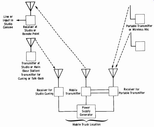
Fig. 8-10. Block diagram of remote-relay system.
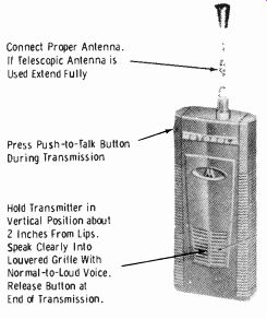
Fig. 8-11. Pocket-size transmitter for remote use.
----- Connect Proper Antenna.
If Telescopic Antenna is Used Extend Fully Press Push-to-Talk Button During Transmission Hold Transmitter in Vertical Position about 2 Inches From Lips.
Speak Clearly Into Louvered Grille With Normal-to-Loud Voice.
Release Button at Ended Transmission.
Solid-state technology and integrated circuits have made possible the design of wireless microphones that are contained in very small cases such as the lavalier or tie-clasp type. The antenna may be a thin wire hanging from the bottom of the case, or it may be wired to an earpiece which contains both the transmitter and receiver for cues. In the latter instance, the antenna is usually a small whip mounted directly on the earpiece. Very small mercury cells often supply the necessary power. The wireless-micro phone transmitter is normally a frequency-modulated device for best signal to-noise ratio. As a general rule, the distance between the wireless-micro phone transmitter and the receiver is kept to 300 feet or less.
Frequency-modulated oscillators vary greatly in design, but most are based on the circuit in Fig. 8-12. Transistor Q1 is sustained in oscillation by a regenerative-feedback tap on L1. The tuned tank circuit (L1 and C1) establishes the frequency of the oscillator, and C1 is sometimes made vari able to adjust the frequency over a narrow range.
The modulating signal from the amplified microphone output varies the emitter-base current, and therefore the collector voltage, of Q2 at the corresponding audio rate. When the Q2 collector voltage increases, the collector-emitter capacitance (C(.,:,) decreases. When the collector voltage decreases, C{,t,, increases. Thus an increase in the capacitance across a portion of the Q1 tank circuit causes the resonant frequency to decrease, and a decrease in capacitance causes the frequency to increase. In this manner, the oscillator frequency is varied at a rate corresponding to the signal applied. It may be observed that some amount of amplitude modulation also occurs due to changes in the collector-to-emitter voltage of Q1, but this is slight. Normally, the rf link feeds a frequency multiplier so that practically all AM is removed; the multiplier also increases the available frequency swing of the oscillator. The final swing is usually between 10 and 20 kHz.
Many of the latest wireless microphones employ a single integrated circuit for the microphone amplifier, oscillator, modulator, and frequency multiplier or power stage. Power output ranges from 30 to 60 milliwatts.
The frequency of operation for broadcast is normally 26.25 MHz.
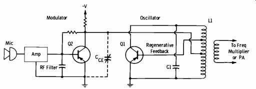
Fig. 8-12. Basic Frequency-modulated oscillator.
8-4. USE OF TELEPHONE LINES
When a program is to originate at some point remote from the regular studios, a number of facilities besides the actual equipment must be considered. A remote broadcast point must check in to the main studio before each broadcast and be able to receive the cue for the start of the remote broadcast. Although some stations, particularly when feeding a network, use two separate lines for this purpose with a "PL" (private line) connected to the talk circuit, most stations now use a single line for broadcast and cue-back.
There are three ordinary positions of a remote key at the studio console which permit proper checking and coordinating functions to be performed.
These are:
1. Override--The key is connected to the proper remote-line pair and is in a position so that when the remote operator calls in he will be heard over the monitor system. In some cases, a separate amplifier and speaker are used so that the check-in by the remote operator does not come in over the regular monitoring system which must, of course, be simultaneously monitoring the program signal.
2. Cue and Talk--In this position, a microphone in the control room (or a telephone handset) may be connected to the line so that the operators may talk to one another for test of the line, time checks, etc.
It may also be terminated from a bridging connection of the monitor lines so that the program at the studio may be fed back over the line for purposes of cueing.
3. Broadcast-In this position, the line is terminated in the mixer control which feeds to the program bus. The remote point is thus fed through the control console in the normal manner.
Fig. 8-13 is a simplified schematic of one general type of remote check-in, cue-in, cue-back arrangement. Key A is a three-position remote key and is the advance selector circuit for keys B, C, and D. For example, when key A is in neutral (the monitor-phone position) and key C is in the override position, the remote operator will be heard over the monitor or an auxiliary amplifier and speaker. Key 13 is the headphone selector key, which may be placed in the remote position when it is desired to talk back to the remote point. To talk back, remote key A is left in neutral, phone-jack key B is placed in the remote position, and the phone or microphone circuit is actuated to talk to the remote point. Usually a talk-back button is used to connect the microphone and disconnect the speaker by relay action. When it is desired to feed the cue-back signal over the line, remote key A is placed in the upper, or cue, position, and the signal from the monitor amplifier is bridged through the adjustable pad into the remote line. When going on the air, key A is simply moved down, or to the mixer input position, and remote-channel key D is thrown to the program position. The remote signal may be fed into the monitor amplifier when key A is in the down position by throwing key D to the audition position.
This is a complete control-coordinating facility for remote controls.
Although the variety of arrangements and components used in practice is great, the general principles are usually the same as those outlined.
Simplex Control of Remote Amplifiers
Many times it is desirable to be able to turn the remote amplifier on and off from the studio. This is desirable for a regularly scheduled broadcast from a point requiring only one microphone where no mixing adjustments are necessary.
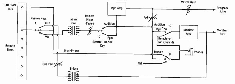
Fig. 8-13
Such switching may be accomplished by means of a simplex installation, as shown in Fig. 8-14. When the remote line is patched into the equipment through the simplex coil, the battery circuit will be completed to activate the relay at the remote point and energize the power-supply circuit of the remote amplifier. This procedure eliminates the necessity of sending an operator to this point for each broadcast.
Equalization of Remote Lines
Although the telephone company usually equalizes the incoming net work lines and regular studio-transmitter broadcast lines, it is beneficial to equalize lines from remote pickup points where the cost of high-class line service is not practical to the station. Most stations have an equalizer of adjustable characteristics in the control room which may be used for this purpose.
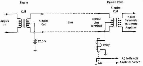
Fig. 8-14. Simplex circuit for control of remote amplifier.
Fig. 8-15 illustrates a typical setup for equalizing a broadcast line. The signal is a steady tone from an audio oscillator which is terminated in an isolation pad. The same load must be presented to the volume indicator at any frequency, and this instrument should, therefore, be bridged on the oscillator side of the pad. The repeat coil properly terminates the line to feed the line equalizer, which is on the load side of the coil and the line side of the line amplifier.
A 1000-Hz tone is usually used and fed to the line at a 0-VU level. The gain of the receiving amplifier is adjusted to give a 0-VU reading at that point. The oscillator is then adjusted to 100, 1000, 3000, and 5000 Hz with constant level maintained at each frequency, and the equalizer is adjusted at the receiving point to compensate as much as possible for the line characteristics at each frequency. This will determine the approximate setting of the equalizer, after which finer adjustments may be made over the entire frequency range.
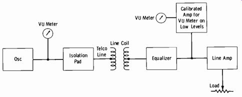
Fig. 8-15. Block diagram of line equalization.
Ordinary AM services usually equalize to 5 or 10 kHz, but fm lines may be equalized to 15 kHz. The insertion loss of the equalizer is approximately equal to the amount of equalization. A calibrated attenuator selects the amount of equalization at the required frequency. The input and output impedances of the line equalizer are usually 600 ohms.
While considering the use of an equalizer, the reader should remember that some loss of signal energy will take place, and some form of extra amplification is necessary. A one- or two-stage isolation amplifier is usually used in conjunction with an equalizer to compensate for this loss; it should have at least a 30-dB gain throughout the frequency range considered.
Telephone Line "Gimmicks"
Telephone talk programs occupy a sizable amount of time at many stations today. Always talk to the local telephone company before initiating the use of the telephone in broadcasting. There are many options available, some of which the telephone company can accommodate with leased equipment at varying monthly charges; you can custom build others with the phone company's blessings. You must always first ascertain the permissible amount of activity in tampering inside the telephone circuitry. Such official activity seems to vary considerably between states and even between various localities within a given state.
The most common official telephone company equipment for broadcast talk programs is the recorder connector illustrated in Fig. 8-16. This unit injects a "beep" into the line every 15 seconds and provides both the send and receive sides of a conversation to the recorder. In the past, this warning signal was required by law so that the calling party was aware that the conversation would be recorded or broadcast. This signal is no longer required by law for regular telephone talk shows, such as a news report from a re mote point, or any prearranged program where all participants are aware of the use intended.
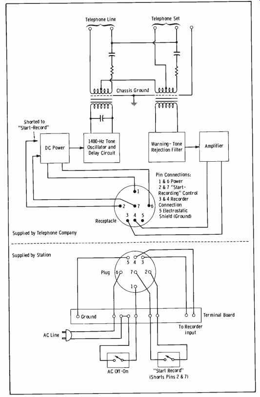
Fig. 8-16. Typical recorder-connector arrangement.
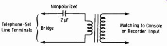
Fig. 8-17. Direct connection to telephone-set line terminals.
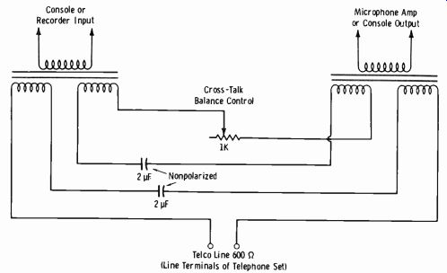
Fig. 8-18. Hybrid circuit for two-way communication.
The simplest device obtainable is the telephone pickup coil. One type consists of a coil loop which clips to the earpiece of the telephone to supply a medium-level input (about-20 dBm) to a recorder or console amplifier.
A symmetrical hum-cancelling pickup coil is best when this simple method is used. It is available at very low cost from most electronic supply stores.
If a direct connection to the line terminals of the telephone set is to be made, use the arrangement of Fig. 8-17. A low-level input, such as the microphone input, may be required for sufficient voice level. When the telephone line is terminated in the set, the impedance is considerably lower than 600 ohms. A 1000- to 2000-ohm bridging impedance is satisfactory.
Another unit that can be built by station personnel is the hybrid circuit of Fig. 8-18. With this arrangement, telephone callers are able to hear the in-studio participants directly from their microphones. The main disadvantage is that the balance control can be nulled to eliminate feedback and minimize return echo distortion for a given line, but it usually needs re adjustment for a different incoming line. This control can be quite touchy even with more elaborate bridge-balancing circuitry than that shown.
One of the most satisfactory methods of telephone-talk programming is presented in Fig. 8-19. This system employs the speaker phone often used for business conferences. The phone is simply removed from the standard cradle, the call made, and the phone placed on the amplifier cradle as shown. The caller's voice appears at the speaker so that all studio participants can hear, and a tap is made from the voice coil to supply the mixing console through an impedance-matching amplifier. The amplifier cradle is normally placed on a common table shared by the microphones of the studio participants. When people in the studio speak in a normal voice, this voice is picked up by the studio-quality microphone for broadcast, and simultaneously by the microphone for the phone amplifier, which enables the caller to hear. The speaker is automatically muted when this micro phone is excited by a normal voice level. The mixing-console operator has complete control over each individual voice level.
8-5. STUDIO-TO-TRANSMITTER LINKS (STL's)
Studio-to-transmitter links (stl's) are often employed rather than wire facilities to relay programs from studio to transmitter. Ten channels in the band 947-952 MHz are allocated by use by STL's. CAUTION: Always check current FCC assignments.
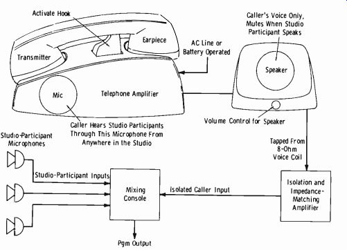
Fig. 8-19. Use of speaker phone in broadcasting.
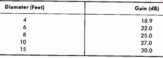
Table 8-2. Parabolic-Antenna Gain in dB in 950- MHz Range
Propagation-Path Calculations
Both the transmitting and receiving antennas are usually half-wave dipoles in parabolic reflectors from 4 feet to 15 feet in diameter. Table 8-2 lists the gain in decibels (over an isotropic radiator at midband) for parabolic reflectors in the 950-MHz range. A strict line of sight must be maintained between antennas used in STL service. The distance to the horizon is based on the fundamental formula:
D = 1.23 VH where, D is the distance to the horizon in miles, H is the height of the transmitting antenna in feet.
Thus if the antenna may be placed 100 feet high, the theoretical distance to the horizon (line-of-sight) is 12.3 miles. However, if it is possible to raise the receiving antenna to 100 feet also, then the distance to the horizon may be found from the equation:
D=1.23(01+ Hr) where,
H5 is the height of the transmitting antenna, Hr is the height of the receiving antenna.
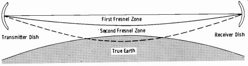
Fig. 8-20. Fresnel zones.
In this case, the effective line-of-sight path becomes 24.6 miles.
Since the preceding basic formulas assume a flat surface, modifications for practical application consider the profile elevations along the projected route of signal propagation. Maps showing elevation contours (height above sea level) at as little as 10-foot elevation intervals are available from local Geodetic Survey offices. Unless the proposed pickup point allows distinct line-of-sight service as observed with the eye, the engineer cannot give a definite opinion until these additional factors are considered.
Microwave energy beamed between two points actually takes an infinite number of paths depending on atmospheric and weather conditions as well as terrain. Refraction may result in either upward or downward directions.
Energy arriving over the various paths is categorized into Fresnel zones.
These zones are numbered to correspond with circles of different radii centered on the direct line between antennas. The zone with the smallest radius is the first Fresnel zone (Fig. 8-20) . The first Fresnel zone contains the energy of a straight-line path plus energy arriving over a closely adjacent path (normally phase additive to the energy on the most direct path).
Many Fresnel zones exist. Energy in the second and all other even-numbered zones has a half-wavelength (180°) relationship to energy in the first Fresnel zone and therefore is a canceling signal. Energy in the third Fresnel zone and all other odd-numbered zones has a full-wavelength (or even multiples of a wavelength) relationship to energy in the first zone and therefore is phase additive.
The primary energy is contained in the first Fresnel zone, and energy contained in even-numbered zones is phase canceling; therefore, it is desirable to obstruct the energy contained in all but the first Fresnel zone.
At the same time, the first zone must be provided ample clearance. A value of 0.6 times the radius of the first Fresnel zone normally is taken as the absolute minimum clearance.
The radius of the first Fresnel zone (at the point of a major obstruction in the path) may be calculated from the equation:
R=72 /AB Pf (Eq. 8-1.)
... where, R is the radius in feet, A is the distance from one end of the path to the point of obstruction in miles, B is the distance from the other end of the path to the point of obstruction in miles, P is the total path length in miles, f is the frequency in GHz.
The following procedure will serve to give the reader a basic understanding of plotting STL paths:
1. Plot a profile of the transmission path. Graph paper which presents the curvature of the earth on a radius 4/3 times its true value may be used. Since ordinary linear graph paper is more convenient for limited use, you may use it and the data of Fig. 8-21. Paper with ten squares to the inch is ideal for this purpose.
2. The path profile and obstructions on the path may be charted from topographic maps. The topographic map gives the heights above sea level of the surface of the earth, to which are added the heights of major obstructions, such as heavily forested areas, water towers, grain elevators, and high-rise buildings. Maps for specific areas may be obtained from the U.S. Geological Survey, Washington, D.C. 20025. For maps of areas west of the Mississippi River, write to the U.S. Geological Survey, Denver, Colorado 80215.
Take the example illustrated by Fig. 8-22A. The bulge (h) of the earth in feet at distance dl miles from the near end and d2 miles from the far end of the path is:
h=0.5d1d2 (Eq.8-2.)
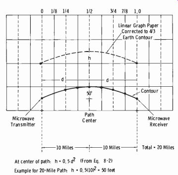
Fig. 8-21. Method of plotting profile of transmission path.
(A) Equal heights. (B) Unequal heights.
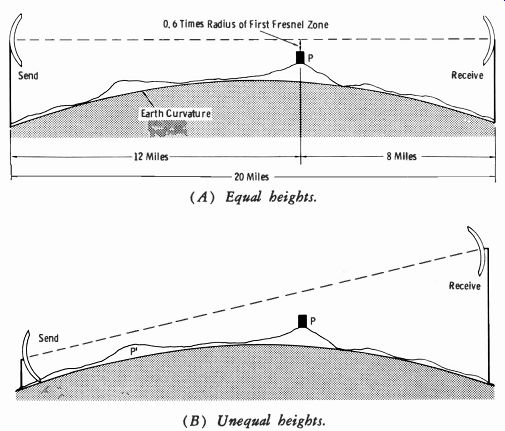
Fig. 8-22. Determination of required antenna heights.
Using equation 8-2 to find the correction for earth curvature at the point of maximum obstruction:
h=0.5 (12) (8) =0.5 (96) =48 feet
Using equation 8-1 to find the radius of the first Fresnel zone at the point in question (point P) , for 950 MHz (0.95 GHz) :
R=72 (12) (8)
=72 (2.23) = 160 feet (approx) (20) (0.95)
Then the minimum clearance is (0.6) (160) = 96 feet.
Now assume that the height above ground of a structure in the path at point P is 100 feet. The earth curvature correction has been found to be 48 feet, and the clearance must be at least 96 feet. The sum of these quantities is 100 + 48 + 96 = 244 feet.
Now further assume that the topographic maps show the sending-end and receiving-end locations to be 1000 feet above sea level and point P to be 111)0 feet above sea level. This adds another 100 feet to the "negative clearance" of the dishes. Thus 244 + 100 = 344 feet is the required height of the sending and receiving dishes for a straight-line path. In case the installation is an STL, the transmitter location normally includes a tall tower on which the receiving dish can be mounted, and the method of Fig. 8-22B might be used. Note that now point P' limits how low the sending dish can be mounted for adequate clearance.
Usually, energy in the second and higher-order Fresnel zones is severely attenuated as a result of normal terrain differences. If the path contains variations of at least 75 percent of the radius of the first Fresnel zone at the center of the path, very little problem is expected from other than first-zone clearance. If the path is very smooth (as over water) , the problems can multiply. This is so because reflections are not dispersed and can be come quite strong.
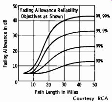
Fig. 8-23. Fading allowance.
When accurate topographic maps are not available, accurately calibrated, sensitive altimeters (properly adjusted in accordance with the barometric pressure) can be referred to a known point or bench mark (American Paulin system) . Or, aircraft-mounted absolute altimeters may be used. In the absence of these devices, conventional civil-engineering techniques must be employed. This is always recommended when there is doubt about a proposed STL path.
Attention to proper first-Fresnel-zone clearance is all that is necessary for the average path, so long as the path length and antenna system are such that the proper fade margin is provided. In evaluating microwave re lay performance, the following fundamentals serve as a basic guide:
1. What field strength in dBW is required at the STL receiver to meet s/n ratio specifications? This is 50 dB for AM use and 60 dB for fm use.
2. Since a microwave beam is sometimes bent and scattered by atmospheric conditions, not only adequate clearance, but also adequate fading margin must be provided.
3. Fig. 8-23 is a graph of fading allowance in decibels versus path length in miles for various reliability factors. For an STL system, the reliability factor must be 99.99 percent. This means that out of a 24-hour pro gram day (86,400 seconds) the signal could deteriorate to something just less than normal program quality for a period of 9 seconds. This 9-second period would not necessarily occur all at one time, but could be accumulative over the 24-hour period. A 99.9 percent reliability factor would allow some 87 seconds in the same program day to deteriorate to less than standard, which is entirely unsatisfactory for STL use.
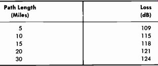
Table 8-3. Free-Space Path Loss at 950 MHz
4. The field strength at the STL receiver is dependent on the free-space path loss (Table 8-3) , the total line loss (Table 8-4) , the total antenna gain (Table 8-2), and the transmitter output in dBW (deci bels above 1 watt) .
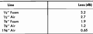
Table 8-4. Transmission Line Losses per 100 Feet at 950 MHz
The values of free-space loss in Table 8-3 are based on the following relationship:
A'=37+20 log f+20 log D where, A' is the free-space loss in dB, f is the operating frequency in MHz, D is the distance in miles is:
For example, the free space attenuation at 950 MHz for a 20-mile path A'=37+ (20) (2.9) + (20) (1.3)
= 37 + 58 + 26
= 121 dB
Suppose you desire to evaluate an STL system that has the following characteristics:
1. Transmitter power output: 6 watts (8 dBW) at 950 MHz
2. Type of transmission line: I/2-inch air
3. Length of transmission line: 330 ft
4. Diameter of reflector at transmitter and receiver: 4 ft
5. Path length: 15 miles
6. Minimum 0.6 Fresnel-zone clearance assumed
The transmission-line loss is 9 dB (Table 8-4) . The antenna-system gain at each end is 19 dB, or a total of 38 dB (Table 8-2) . The combination of transmission-line loss and antenna gain is 38-9 = 29 dB. The net path loss is:
A=A'- Gt where, A is the net path loss, A' is the free-space loss (Table 8-3) , Gt is the combined transmission-line loss and antenna gain.
In this example:
A = 118- 29
= 89 dB The receiver power input is:
Pr=Pt-A where, P,. is the receiver power input, P,; is the transmitter power output in dBW, A is the net path attenuation.
Thus in this example:
Pr=8-89
=-81 dBW
The fade allowance for 99.99-percent reliability (15-mile path) is approximately 16 dB (Fig. 8-23). Therefore the signal at the receiver with fade is -97 dBW, or 100 microvolts (Table 8-5).
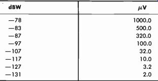
Table 8-5. Signal Level in dBW Across 50 Ohms and Signal Strength in µV
In this example, if the receiver requires 34 µV in 50 ohms for a 60-dB signal-to-noise ratio, there is a safety factor of 100/34 = 2.94, or about 9 dB. This is over and above the required fade margin, and the installation normally would be considered adequate.
The Marti STL System
The Marti STL-8 transmitter is shown in Fig. 8-24A, and the companion R-200/950 STL receiver is shown in Fig. 8-24B. The basic block diagram of the transmitter appears in Fig. 8-25 and that of the receiver in Fig. 8-26.
The maximum licensed power of the transmitter is 8 watts, and this unit is normally operated at around 6 watts under average safety-factor applications. Direct fm is employed with plus and minus 52.5 kHz constituting 100-percent modulation. The standard 75-µs pre-emphasis network is used at the transmitter, with corresponding de-emphasis in the receiver. Remote-control and/or subcarrier inputs are provided.
(A) Transmitter. (B) Receiver. Courtesy Marti Electronics, Inc.
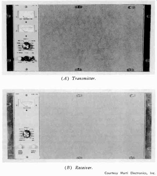
Fig. 8-24. Equipment for STL.
The fm modulator (Fig. 8-25) employs a phase-shift network in the transistor oscillator circuit, with varactors (voltage-variable-capacitance diodes) used to determine the oscillator frequency. The varactor bias is initially adjusted to 6 volts, and audio is fed to this network to vary the oscillation frequency at the corresponding audio rate. The oscillator frequency is 1/216 of the final operating frequency.
Both the frequency and power are multiplied in the following stages as shown in Fig. 8-25. The actual rf power-amplifier output is 23 watts, which results in 8 watts at the output of the final varactor multiplier and filter network. This final stage employs varactors in tuned transmission lines, which function as highly stable frequency multipliers, with an output containing spurious emissions more than 60 dB below the carrier. The overall frequency stability of this unit is at least 0.0005 percent between tempera ture extremes of -30° and +60°C, with +25°C as the reference.
The R-200/950 receiver requires only 32 µV for a 60-dB or better signal-to-noise ratio. A crystal controlled, double-conversion system is used (Fig. 8-26).
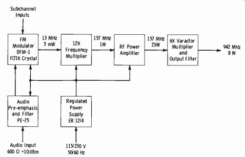
Fig. 8-25. Block diagram of STL transmitter.
The Marti SCG-8 subcarrier generator and the SCR-8 subcarrier receiver are intended to be used in conjunction with the 950-MHz aural STL, to transmit any type of auxiliary program material from the studio to the transmitter location over one of the subchannels of the link. Used primarily to transmit background music material, they can be used equally as well (with the proper auxiliary equipment) to provide a telephone communications circuit to the transmitter.
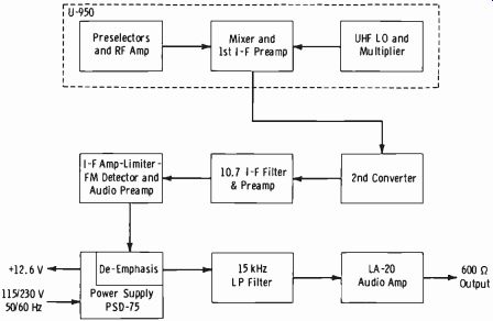
Fig. 8-26. Block diagram of STL receiver.
The SCG-8 subcarrier generator can also be used with most fm broadcast transmitters to inject background music onto the 41- or 67-kHz fm sub-carrier. Many stations which use radio remote pickup equipment prefer to move their base receiving antenna and remote-pickup receiver to the fm transmitter site and feed the rpu audio back to the studio over the 67-kHz subcarrier, in order to achieve maximum tower height for the rpu antenna.
When the SCG-8 generator is used to feed the rpu audio to the studio, the audio is recovered on a subchannel frequency-modulation monitor for reprocessing.
Both the generator and receiver are supplied with an extremely sharp 6-kHz low-pass filter to prevent cross talk between the subchannel and main channel. Care has been exercised to insure extensive shielding and filtering for operation in strong rf fields.
For fm stereo, maximum reliability is reflected in the dual- or split-channel approach, in which two transmitters and two receivers are used, combined into a common antenna system. Fig. 8-27 is a diagram of a typical system employing stereo, SCA, and transmitter remote control. (Transmitter remote control using STL's is described in the next section.) The transmitter combiner is a device commonly used for operating two STL transmitters into a common antenna and transmission-line system. While used primarily for fm stereo application in the split- or dual-channel system, it can also be used in "hot-standby" applications. The combiner presents a 3 dB loss to the system, but in most cases is less expensive than using separate antenna and transmission-line systems. More than adequate isolation is maintained between transmitters, and the combiner has a 20-watt resistive load built in. A special precision-cut T matching section is available for receivers; it also presents a 3-dB loss. Thus the total loss of the combiner technique is 6 dB, and this must be accounted for in path computations.
The dual-channel concept allows the stereo generator to remain at the fm transmitter site, preventing continual adjustment by unauthorized and uninstructed personnel, and eliminating the need for expensive interface equipment between the STL system and the fm broadcast transmitter. In addition, such problems as inadequate separation can be diagnosed more easily when the system is arranged so that the stereo generator is not combined with the STL system.
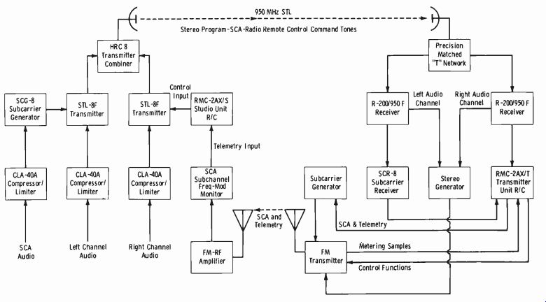
Fig. 8-27.
8-6. TRANSMITTER REMOTE CONTROL VIA STL
Fig. 8-28A is a view of the Marti RMC-2AXS studio unit, and Fig. 8-28B is a view of the companion RMC2-AXT transmitter unit. Designed for AM and fm subaudible telemetry, this remote-control system requires no interface equipment to meet requirements of the FCC Rules and Regulations pertaining to the mixing of the subaudible telemetry, filtering, and prevention of overmodulation. These circuits and components are an integral part of the basic studio and transmitter units.
Of all solid-state design and employing modular construction techniques, the RMC-2AX is available as a 22-function system having 10 metering positions, or, for the more complex installation, an optional 50-function system with 24 metering positions is available.
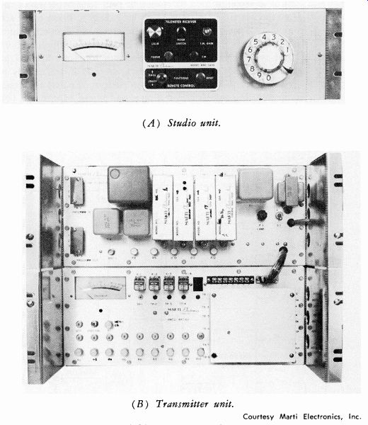
Fig. 8-28. Remote control system.
--- (A) Studio unit. (B) Transmitter unit. Courtesy Marti Electronics, Inc.
Subaudible telemetry is accomplished through the use of a voltage-con trolled oscillator with a frequency shift of from 22 to 28 Hz at a low percentage of modulation. A high-pass filter is used to prevent the program audio component from modulating the metering channel. Automatic compensation is provided to limit the total modulation to 100 percent modulation while telemetering.
The same system can be used to meter an fm transmitter, except the fm 67-kHz subcarrier is modulated with the metering information through a subcarrier generator. The information is usually recovered at the studio on a subchannel frequency-modulation monitor or on a multiplex receiver.
The subcarrier may also be used for background music.
Remote control is accomplished by means of four supersonic tones injected into J1 of the Marti STL-8 transmitter (Fig. 8-29) . These tones are recovered from the output of the microwave receiver and connected into the RMC-2AXT (A) unit (Fig. 8-30) at the transmitter through a short RG-58A/U cable with BNC connectors. These four tones are applied to four tuned amplifiers which select one tone each, amplify it, and rectify it to operate a function relay. The function relays perform the dial and reset operation of the stepping switch and the raise and lower adjustment (of the transmitter under control) in each position of the stepping switch.
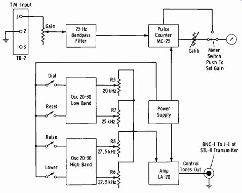
Fig. 8-29. Block diagram of remote-control studio unit.
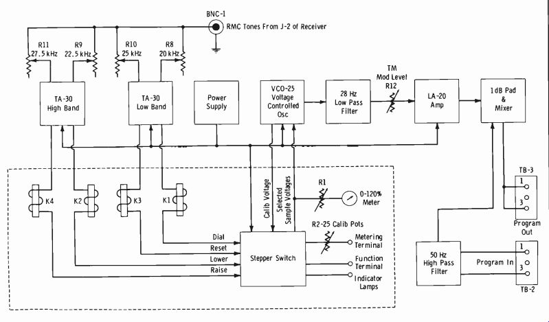
Fig. 8-30.
The telemetering of the data concerning transmitter operation back to the studio is accomplished as follows. Each circuit to be tele-metered is equipped with a sampling resistor to provide a dc voltage drop of 1.6 to 2.5 volts. (Modern broadcast transmitters are supplied with voltage and current sampling circuits.) Each sampling circuit is connected to a pair of RMC-2AXT metering terminals. A 10-turn potentiometer is provided for each metering circuit to provide a precise adjustment to 100 percent on the RMC-2AXT meter. Thus, when, for example, the transmitter plate current is at its normal (100-percent) value, the sampled voltage drop developed by this current is adjusted to read 100 percent on the RMC-2AXT meter.
A decrease in transmitter plate current of 5 percent would then produce a 5 percent reduction in this sampled voltage drop and be tele-metered back to the studio as such. At the studio, a chart must be prepared to allow fast conversion of percentage readings to voltage, current, and power quantities for entry into the station log. Details of this procedure as well as remote adjustment and control are covered in Section 11.
In order for the sampled dc voltage to be transmitted by radio, a converter must be employed to produce an ac signal which is a linear function of the dc voltage sample. This converter is a voltage-controlled oscillator which operates over a frequency range of 22 to 28 Hz (corresponding to dc sample voltages of zero to 120 percent) . These subaudible frequencies are selected to permit the transmission of the telemetry information at low level on the audio program channel ( AM or fm SCA) without noticeable degradation of the program quality. In order to prevent extraneous low-frequency program audio components from interfering with the telemetry tone, a high-pass filter is used in the program line before the transmitter modulator to attenuate frequencies below 50 Hz. A bandpass filter is also required at the studio unit to separate the 22-28 Hz telemetry tone from the program material. Reference to the system block diagrams (Figs. 8-29 and 8-30) will aid in the understanding of the signal processing described above.
Another converter must now be used to convert the recovered telemetry tone linearly to an analog display (meter reading) . This conversion is performed by the MC-25 pulse-counter module in the studio unit. The system is accurately calibrated before the readings are taken by dialing position 1 at the studio. This switches in a standard reference voltage at the transmitter unit and allows the studio meter to be adjusted to " Cal" (100 percent) by means of the CALIB knob.
The Marti STL remote-control system has the following specifications:
Remote Control Functions Model RMC-2AXT ( 10 ) Model RMC-2AXT (25 ) Metering Model RMC-2AXT ( 10 ) Model RMC-2AXT (25 ) 10 Raise commands 10 Lower commands 25 Raise commands 25 Lower commands 10 Telemetering channels including calibration
25 Telemetering channels including calibration
Metering Input Requirements 1.6 to 2.5 volts dc, either polarity to ground or referenced above ground not to exceed ±200 volts dc. Metering input resistance greater than 12,000 ohms.
Metering Calibration
Calibration voltage derived from double regulated zener diode, oven temperature controlled. Ten-turn vernier potentiometers provided for all metering adjustments. Four-inch, mirror-scale, taut-band meters with one-percent accuracy provided.
Remote Control Frequencies
For STL: 20 kHz Dial function 22.5 kHz Lower function 25 kHz Reset function 27.5 kHz Raise function For Line: 600 Hz Dial function 980 Hz Lower function 1450 Hz Reset function 2250 Hz Raise function Telemetry Tone Frequencies 22 Hz to 28 Hz corresponding to metering sample voltages of 0 to 120 percent of normal (100 percent) Telemetry Tone Purity Less than 2 percent the at 27 Hz (10 dBm ) Telemetry Accuracy Plus or minus 2 percent of full scale Telemetry Tone Output Level, RMC-2AXT (A) Adjustable from-35 dBm to +10 dBm (measured at "program out" terminals) Impedances Program in, program out, and telemetry input (TB-2 of RMC-2AXS) are all 600 ohms Operating Environment Air Temperature Range-10° C to +40° C Power Requirement 110 to 125 volts, 50/60 Hz
EXERCISES
Q8-1. Give the frequency band for STL microwave systems.
Q8-2. Do the frequency bands differ between STL service and mobile service?
Q8-3. What is the absolute minimum first-Fresnel-zone clearance recommended?
Q8-4. Define "first Fresnel zone."
Q8-5. Why should strictly over-water paths be avoided where possible?
Q8-6. Is the signal modulation for microwave systems normally AM or fm?
Q8-7. What type of line couples the energy from the output stage to the antenna?
Q8-8. What is the signal-to-noise ratio required in an STL system for:
(A) Use with AM broadcast transmitters (B) Use with fm broadcast transmitters.