Audio-frequency power amplifiers are used in all public-address systems, radio and television receivers, record players, recorders, etc., to provide sufficient audio power to drive the speakers or other devices connected to its output. Speakers are usually cur rent-operated devices requiring a fairly heavy electron current to flow at the audio frequencies. The power developed across any resistive load varies as to the square of the current flowing through that load, in accordance with the power formula which states that:
P(orW)=I^2 X R
where,
P is the power in watts, I is the current in amperes, R is the resistance of the load in ohms.
A tube used as a power amplifier is designed to deliver a large quantity of cathode-plate current. The current is normally de livered to a transformer in the load circuit. This enables the particular speaker load to be matched in impedance with that of the plate circuit. An exact match between the two impedances is necessary for optimum, or maximum, transfer of power from the plate circuit to the load circuit.
Since the impedance of the average speaker is fairly small ( on the order of a few ohms), and since the plate-circuit impedance will be much larger, the impedance-matching process takes ad vantage of the turns ratio (which is a manufactured characteristic of transformers). The impedance-matching characteristic of a transformer varies in accordance with the square of the turns ratio between the primary and secondary windings. If a primary winding has twice as many turns as the secondary, the turns ratio--normally expressed as N1 --;- N2-will be 2, or 2-to-1, and the transformer can match two impedances in the ratio of 4-to-1.
If a turns ratio is 20-to-1, the transformer can match two impedances which differ from each other by a factor of 400-to-1.
Thus, if a speaker has an impedance of 8 ohms and the plate circuit an impedance of 3,200 ohms, the two impedances can be matched to each other by using a transformer having a 20-to-1 turns ratio between the primary and secondary.
Sample circuits have been chosen to depict circuit conditions and problems during audio-frequency power amplification. The first circuit uses a single power-amplifier triode. All use output transformers of the current step-up type. In the first example, the movement of the output current through the speaker coil, and the resultant movements of the speaker diaphragm, will be discussed in detail. The later examples represent typical push-pull circuits. This portion of the discussion has not been repeated here, since the principles are identical for all circuits.
TRANSFORMER-COUPLED POWER AMPLIFIER
Figs. 1 and 2 show two successive half-cycles in the operation of a conventional audio-frequency power amplifier. A trans former couples the plate circuit to the load, which is shown as a speaker. This type of circuit must be operated under Class-A conditions, meaning the plate current must not be cut off, or interrupted, during any portion of an individual cycle. Self biasing is accomplished by using a cathode resistor and bypass capacitor. The power-amplifier tube is driven by the output from the preceding voltage amplifier.
The components which make up this complete circuit are as follows:
R1-Grid driving and grid-return resistor.
R2-Cathpde biasing resistor.
C1-Cathode filter capacitor.
T1-Audio-frequency output transformer.
V1-Power-amplifier triode.
Ml-Power supply.
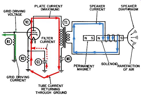
Fig. 1. Operation of an AF power amplifier-first half-cycle.
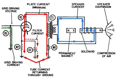
Fig. 2. Operation of an AF power amplifier-second half-cycle.
Identification of Currents
The currents at work in this circuit include:
1. Grid driving current (green).
2. Plate current (pulsating DC), (solid red).
3. Speaker or output current (blue).
4. Cathode filter current (dotted red).
In addition to these currents, provision is always made for the possibility of grid-leakage current flowing out of the tube, and for the necessity of furnishing it a return path to the cathode.
Resistor R1 provides this return path. Since the circuit operation as a whole does not depend on grid-leakage current, however, it is not shown in Figs. 1 and 4-2.
Details of Operation
Fig. 3-1 is considered the positive half-cycle of operation because the voltage at the grid is increasing in the positive direction throughout the entire half-cycle. The upward flow of grid driving current through R1 during this first half-cycle exists be cause electrons will always flow toward areas of more positive voltage.
As the grid voltage becomes more positive, more and more plate current will be released through the tube. Throughout the ranges of grid voltage and plate current in which this operation is carried out, it is desirable that the amount of plate current bear the same proportion to the amount of grid-cathode voltage at all times. When this condition is achieved, the tube is considered to be a linear amplifier. This term is derived from the characteristic curve for a triode (shown in Fig. 2-3). The complete path for plate current (shown in solid red) is of course from cathode to plate, downward through the primary winding of the output transformer, through the power supply, and into the common ground. From here it flows through resistor R2 to the cathode. During that portion of a cycle when this current is increasing as it flows down through the primary winding, it will induce more and more current to flow in the opposite direction in the secondary winding. This secondary current, shown in blue, is the one which actually drives the speaker diaphragm.
During the second, or negative, half-cycle in Fig. 2, the direction of grid driving current and resultant grid voltage are re versed from that shown in Fig. 1. The gradual reduction in grid voltage causes a continual reduction in the plate current through the tube. As this decreasing plate current flows downward through the primary winding, it will simultaneously cause the current in the secondary winding to decrease in the opposite direction from the plate current, which is actually an increase in the same direction (downward) as shown by the blue line in Fig. 1. This is how a pulsating direct current in one winding can actually cause an alternating current to flow in the other winding. Thus, from one half-cycle to the next, the output currents in the secondary winding and speaker coil alternately flow in the opposite direction.
Speaker Action
A transducer is broadly defined as a device for converting energy from one form into another. A speaker qualifies as a transducer because it converts the electrical energy represented by the output current into sound energy which can be heard. As shown in Figs. 1 and 2, this is accomplished with the aid of a permanent magnet, a movable solenoid, and a diaphragm which is connected to the solenoid and moves with it to set up the air vibrations we know as sound waves.
The solenoid operates on the same principle as the electro magnet. When electron current flows through a coil of wire, magnetic lines of force are established which pass through the coil in an axial direction. Furthermore, the direction (polarity) of these lines of force depends on the direction of the electron flow through the coil. The polarity of these or any magnetic lines of force is either north or south.
The magnetic lines of force ( also called lines of flux) are greatly strengthened by placing an easily magnetized material, such as soft iron, within the coil. This has been done in the speaker of Figs. 1 and 2. The polarity of the magnetic field created, as a result of the electron current through the moving coil, has a north pole at the left end and a south pole at the right end of the coil, as shown in Fig. 1.
This combination of a coil of wire and a movable iron core becomes a solenoid with the addition of a permanent magnetic field to the temporary one. This permanent magnetic field is provided by the magnet in Figs. 1 and 2. Its permanent south pole is on the right, adjacent to the left end of the movable iron core. When the core is magnetized, as shown in Figs. 1, it will be drawn to the left, closer to the permanent magnet, since a south and a north magnetic pole will always be attracted to each other. The core pulls the flexible diaphragm with it, creating a "rarefaction" of the air in front of the speaker, which becomes one half of a single cycle of a sound wave.
When the direction of the output current in Fig. 3-2 has been reversed (Fig. 2) the resulting magnetic lines of force change direction. The movable iron core now has a south magnetic pole at its left end and a north magnetic pole at its right end.
Since the two south poles repel each other, the entire core moves to the right, pushing the flexible diaphragm ahead of it. This diaphragm movement compresses the air in front of the speaker which becomes the other half of a single cycle of a sound wave. A sound wave consists of these alternate compressions and rare factions of air traveling through the atmosphere. When these air vibrations strike another transducer such as the human ear, they are "transduced" to appropriate nerve vibrations, bringing pleasure (presumably!) to the listener.
The frequency of the output current determines the frequency, or pitch, of the sound produced. As an example, if the current frequency is 400 cycles per second, the iron core will move back and forth 400 cycles each second and thus accurately reproduce the desired pitch.
The volume of sound produced depends on the distance the diaphragm travels back and forth each cycle. This will be the same distance as the one traveled by the iron core, since the two are rigidly joined together. The strength of the alternating cur rent through the secondary winding determines the strength of the temporary magnetic field, which in turn regulates the movements of the iron core.
The Permanent Magnet
The permanent magnet shown in Figs. 1 and 2 to attract or repel the solenoid is used in the majority of speakers. How ever, in some speakers, a coil of wire is wound around an iron core and connected to a source of direct current. Thus we have a second electromagnet. Unlike the solenoid electromagnet, how ever, the magnetic field for this second electromagnet will remain constant and the poles unchanged because it is connected to a DC source instead of the AC through the solenoid coil.
How do we tell which pole is which in an electromagnet? It's simple! Just grasp the coil with the left-hand so that your fingers point in the direction the electrons are flowing through the coil.
Then extend your thumb, and it will point toward the north magnetic pole.
Speakers employing permanent magnets are called permanent magnet, or PM, speakers, while those with electromagnets are called electromagnetic or EM speakers. Operation of both types is the same-the only difference is the added connections for the extra coil, usually called the field. In practice, the field is usually connected to a DC source in the equipment's power supply, but sometimes a separate power supply is used.
Cathode Filtering
The cathode filter or bypass current, shown in dotted red, flows back and forth into and out of capacitor C1. Its only purpose is to keep the voltage at the cathode constant. Remember that the grid bias of any tube is the instantaneous difference in voltage between grid and cathode. The actual voltage at the grid is changed by the flow of grid driving current up and down through the grid driving resistor, and it is desirable that the amount of plate current, at any instant throughout the cycle, always be proportional to the grid driving voltage. If we were measuring grid driving voltage with respect to a fixed value such as ground, this condition would be relatively simple to attain. However, we are really measuring the grid driving voltage with respect to the cathode, since the total instantaneous grid bias (which really determines how much plate current will flow) is the difference be tween the cathode and grid voltages. Therefore, the cathode should, insofar as possible, be held at some fixed value of positive voltage.
It is obvious that the cathode voltage is subject to fluctuation, since it is produced by the flow of plate current through cathode biasing resistor R2 and the plate current is varying over a fairly wide range. The addition of a filtering capacitor stabilizes this cathode voltage and thereby prevents such voltage fluctuations.
The combination of resistor R2 and capacitor C1 is a familiar example of a long time-constant RC filter. A positive voltage builds up on the upper plate of capacitor C1. When the demand for plate current is very low (the condition depicted in Fig. 3-2), this positive cathode voltage continues to draw electron current upward through the cathode resistor. During these negative half cycles the excess electron current "spills over" onto the capacitor rather than entering the tube. This action drives an equal number of electrons off the lower plate and into common ground.
During the positive half-cycles depicted by Fig. 3-1, the control grid is positive; hence the demand for the cathode to emit more electrons into the tube increases. If there were no cathode bypass capacitor, the additional plate current would have to be supplied directly from ground, below the cathode resistor. In flowing upwards through R2 this current would cause an in creased voltage drop across the resistor, in accordance with Ohm's low. The larger drop would result in a higher positive voltage at the cathode.
When a suitable bypass capacitor is connected across the resistor, the additional demand for plate-current electrons will be supplied directly from the positive ion pool on the upper plate of the capacitor. If the capacitor is large enough in value, the ion pool will be large enough that an insignificant number of extra electrons will be given up into the tube, in comparison with the number of positive ions stored there. Hence the positive voltage of the ion pool will not be changed noticeably by the departure of the electrons.
The filtering current which flows between the lower plate of the capacitor and ground will flow upward during the positive half-cycle of Fig. 3-1, drawn by the departure of the extra electrons into the tube.
Thus we see that the filtering current flows up and down between the capacitor and ground at the frequency of the applied voltage.
ADVANTAGES OF PUSH-PULL OPERATION
Several important advantages accrue from using two power amplifier tubes in push-pull connection. As discussed in earlier Sections, it is normally desirable to operate a tube on the linear portion of its transfer characteristic curve in order to avoid distortion. The distortion arising from operating a tube along non linear portions of this curve is classified as second-harmonic distortion. In the push-pull connection, the second-harmonic distortion caused by one tube is canceled out, in the output transformer, by second-harmonic distortion caused by the second tube. Consequently, the output is essentially distortionless. The fact that these two distortions can be canceled out permits each tube to be driven harder-in fact, into the nonlinear portions of the characteristic curve. The power output achieved from two tubes in push-pull is more than double the power that can be achieved with a single tube of the same type. This feature permits the use of two lower power tubes in push-pull, instead of one high power tube, to achieve the desired power outputs.
Another advantage of the push-pull circuit is that DC magnetization of the output-transformer primary winding is avoided.
In the circuit just discussed, some plate current is flowing down ward through the primary winding at all times. (This can be verified by examination of Figs. 1 and 2.) As a result of the continuous current through one winding, the iron core becomes magnetized and this detracts from its ability to operate efficiently as a transformer. This undesirable effect is eliminated in all the other circuits of this Section, since any permanent magnetism which might otherwise be acquired as one plate current flows downward through part of the primary winding will be canceled out (neutralized) by the other plate current flowing upward through the other portion of the primary.
Still another advantage of a push-pull connection is that the sum of the two currents entering the power supply is very nearly constant, particularly when the tubes are being operated under Class-A conditions. This eliminates the necessity of decoupling the power supply with an additional filter capacitor to bypass small surges in current around the power supply to ground. Be cause a single power supply is normally used to supply many circuits, it is essential that no voltage or current surges be permitted to momentarily raise or lower the power-supply voltage, since the operating conditions of all other tubes connected to the power supply would be immediately affected.
Because of the symmetrical relationship between the two grid voltages and the resulting plate currents, a push-pull circuit is sometimes referred to as a balanced amplifier.
PUSH-PULL AMPLIFIER USING GRID-LEAK BIAS
Figs. 3 and 4 show two successive half-cycles of operation of a push-pull power amplifier for audio frequencies. A transformer is used in the input circuit to supply driving voltages to the two tubes. These driving voltages must be equal in amplitude but 180° out of phase with each other. There are several methods of meeting the two conditions. The transformer input is one.
This circuit has the following components:
R1-Grid-leak biasing resistor for both tubes.
C1-Grid-leak biasing capacitor for both tubes.
T1-Input transformer.
T2--Output transformer.
V1-First power-amplifier triode.
V2-Second power-amplifier triode.
M1--Common power supply for both tubes.
There are seven different electron currents at work in this circuit:
1. Input-signal current flowing in primary of transformer T1, (blue).
2. Grid driving current flowing in secondary of transformer T1, (solid green).
3. Grid-leakage current for V1 ( dotted green).
4. Grid-leakage current for V2 (also in dotted green).
5. Plate current for V1 (red).
6. Plate current for V2 (also in red).
7. Output current flowing in secondary winding of transformer T2 (blue).
Circuit Description
As indicated in Figs. 3 and 4, the secondary winding of transformer T1 has more turns than the primary. This indicates the transformer is a voltage step-up and current step-down type.
This transformer is being driven by the input signal current, shown in blue in Fig. 3. The primary current is shown flowing downward through the primary winding.
The action of any transformer or inductor is to oppose any change in the total current flowing in the two windings. Thus, if we consider that fraction of the first half-cycle when the input signal current is building up as it flows downward through the primary winding of T1, we can immediately visualize a different current being caused to flow upward in the secondary winding.
The latter also is increasing, so that the total current flowing in the two windings (the algebraic sum of the two currents) will be considerably less than if the secondary current did not flow.
This induced current, shown in solid green in Fig. 3, flows upward in the secondary winding. Associated with this secondary current is the back emf or counter emf. Its polarity during this portion of the first half-cycle is indicated by the plus sign at the top and the minus sign at the bottom of the secondary winding.
(It is easy to correlate these polarities with the upward flow of secondary current, since electrons will always flow toward a positive voltage and away from a negative one.) The positive polarity also exists at the control grid of V1 during the first half-cycle. This positive grid voltage releases a large amount of plate current through V1. The complete path of the plate current (in red) is from cathode to plate, downward through the upper half of output transformer T2 to its center tap, then through common power supply Ml to ground, and back to the cathode.
Since the control grid of tube V2 is connected to the lower end of the secondary winding of input transformer T1, its grid voltage will always be 180° out of phase with the voltage applied to the grid of V1. This condition is indicated in Fig. 3 by the minus sign at the bottom of the secondary winding. The negative voltage at the grid of V2 drastically restricts the flow of plate current through V2 during this half-cycle. The complete path of plate current for V2 is from cathode to plate within the tube, upward through the lower half of the primary winding of output transformer T2, then through the common power supply to ground, and back to the cathode of V2.
Capacitor C1 and resistor R1 serve as a common grid-leak bias combination for both tubes. Leakage electrons which strike the grid of either tube must flow back to ground through the appropriate half of the secondary winding of transformer T1, and then through resistor R1. If R1 has a sufficiently high resistance, all grid-leakage electrons from both tubes will accumulate on the left plate of capacitor C1, and a negative voltage will build up and be applied equally to the control grid of each tube. This negative voltage, known as a grid-leak bias voltage, is characterized by an intermittent input of new electrons from each tube once each cycle, and by a continuous drain of electrons from the capacitor, through resistor R1 and back to ground.
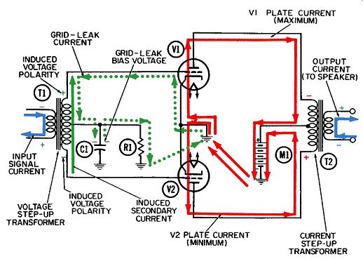
Fig. 3. Operation of a push-pull AF power amplifier using grid-leak bias-first
half-cycle.
A circuit constructed in this manner-with a transformer in the input portion-will normally be operated Class-A, which means each tube is conducting some plate current during the en tire audio-frequency cycle. Thus, in Fig. 3, when V1 conducts heavily, V2 will conduct lightly. During the second half-cycle, V2 will have a more positive grid voltage and will conduct heavily while tube V1 will have a negative grid voltage and consequently conduct only a small amount of plate current. The plate current in each tube is a pulsating direct current, and the pulsation from each tube will cause transformer action between the primary and secondary windings of T2. These two separate transformer actions will fortunately be in the appropriate phase to aid, or reinforce, each other. As a result, a very heavy secondary current (in blue) will flow in the output circuit. This output current is a greatly amplified version of the small input-signal current, also shown in blue, which flows up and down in the primary winding of T1.
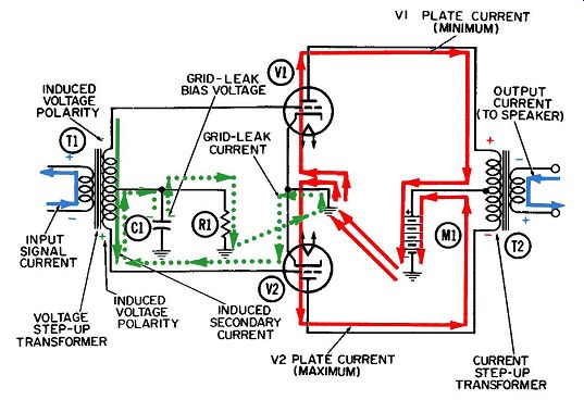
Fig. 4. Operation of a push-pull AF power amplifier using grid-leak bias-second
half-cycle.
Notice, transformer T1 has more turns in its secondary than in the primary. Therefore, it steps-up the voltage (and steps-down the current) before applying it to the two control grids, since vacuum tubes are voltage controlled devices. Transformer T2, on the other hand, has more turns of wire in its primary than in its secondary winding. So it will act as a current step-up ( and voltage step-down) transformer. This is advantageous for this reason-the transducer (speaker) to which the secondary winding of the output transformer is connected will usually be a current operated device. Hence, the volume of sound available will depend directly on the strength, or amplitude, of the current pulsations flowing through the speaker coil. The speaker current, and the current through the secondary winding of transformer T2, are of course one and the same.
Transformer Action
Let us consider the transformer actions as a result of the two plate currents in Fig. 3. During the first half-cycle the plate current starts at its minimum value and increases continuously until it reaches its maximum value at the end. As this current flows downward through the upper half of the primary winding of T2 at an increasing rate, another current will be induced to flow upward in the secondary winding (also at an increasing rate) be cause the natural tendency of any transformer is to oppose any change in the total current flowing through the windings. Associated with these two currents are appropriate voltage polarities, the signs of which are indicated at the tops of the primary and secondary windings. An increase in plate current is normally associated with a reduction in plate voltage, because of the greater number of electrons in the plate area. This is the meaning of the minus sign at the top of the primary winding in Fig. 3.
By definition, a back emf always has a polarity opposite that of the applied emf, or voltage. Consequently, in Figs. 3, the resulting back emf in the secondary winding of T2 will have a positive polarity at the top. It is possible to correlate both voltage polarities with the directions of current flow indicated-more electrons flow away from the minus sign in the primary winding, and more electrons flows toward the plus sign in the secondary winding.
During the same first half-cycle (Fig. 3), current through V2 starts out at its maximum value and decreases to minimum at the end of the half-cycle. Associated with this decrease in plate current is the conventional rise in plate voltage. The latter can be symbolized by the plus sign at the bottom of the primary winding, which also designates the polarity of the applied emf across the lower half of the primary.
The resulting back emf across the secondary winding will have a negative polarity at the bottom of the winding, as indicated by the minus sign. Associated with this polarity will be a flow of electron current away from the negative region and upward through the winding.
Hence, during the first half-cycle two different components of secondary current are made to flow in phase with each other by the two streams of plate current, thus making a very heavy cur rent available for operating the speaker.
During the second half-cycle (Fig. 4) most of the previous conditions are reversed. The direction of signal current in the primary of the input transformer T1 is upward, and the resulting back emf in the secondary winding is positive at the bottom. This causes a steady increase in the plate current through tube V2, with the resultant lowering in plate voltage and a negative polarity sign for the applied emf across T2. The resulting back emf across the secondary winding will have a positive polarity at the bottom, indicated by the plus sign, and during this half-cycle electron current will of course be flowing downward in the secondary winding at an increasing rate.
As the control grid of tube V1 becomes progressively more negative during this second half-cycle, the plate current through V1 decreases. This causes a rise in plate voltage, as indicated by the plus sign at the top of the primary winding of T2. The transformer action across T2 gives a back emf of negative polarity at the top of the secondary winding, as indicated by the minus sign. Therefore, electron current flows downward through the secondary winding.
Thus, the two transformer actions resulting from the two plate currents will drive currents in the secondary winding, which are in phase during each half-cycle of operation. This feature is of course the special attractiveness of the push-pull circuit.
Plate and Grid-Leak Currents
For the newcomer to electronics, the complete path of plate and grid-leakage currents will now be briefly reviewed.
Electrons which leave the cathode and reach the plate of tube V1 will flow through the upper half only of the primary winding of transformer T2 before being drawn into the positive terminal of power supply M1 and delivered through the power supply to ground and back to the cathode. It is of course the high positive voltage of the power supply which causes this entire sequence to occur, since this voltage provides the positive plate voltage which draws the electrons across the tube.
By similar reasoning, the plate-current path for tube V2 is from cathode to plate, upward through the lower half only of the primary winding of transformer T2 to the positive terminal of the power supply, through the power supply to ground, and back to the cathode.
Grid-leakage electrons will flow out of the tubes via the control grids whenever a control-grid voltage is more positive than the cathode voltage. In tube V1 this will occur near the middle of the first half-cycle, and in V2, near the middle of the second half cycle.
Grid-leakage electrons from both tubes must flow back to their respective cathodes through half of the secondary winding of T1 and through resistor R1. Prior to entering R1, the electrons will accumulate on the top plate of capacitor C1 and form a reservoir of negative voltage (known as the grid-leak bias voltage) . This voltage biases the control grids of both tubes to the same negative value.
Fig. 5 gives the time relationship between the voltages at the two control grids, the two plate currents, and the output cur rent flowing in the secondary winding of transformer T2 in graphical form.
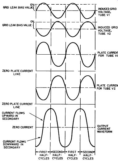
Fig. 5. Voltage and current waveforms in the amplifier of Figs. 3 and 4.
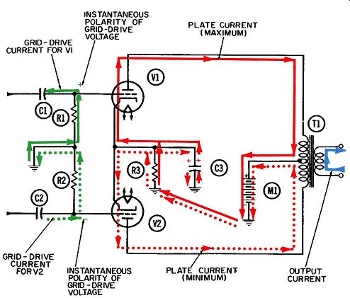
Fig. 6. Operation of a push-pull AF power amplifier using cathode bias-first
half-cycle.
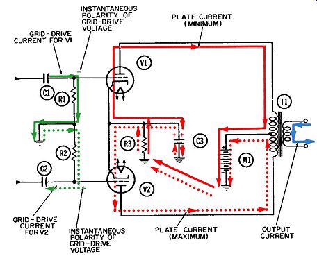
Fig. 7. Operation of a push-pull AF power amplifier using cathode bias-second
half-cycle.
PUSH-PULL AMPLIFIER USING CATHODE BIAS
Another common type of push-pull power amplifier is given in Figs. 6 and 4-7. Notice that here two signals, each 180° out of phase, drive the grids of the push-pull amplifier tubes. (How these two 180° out of phase signals are obtained is explained in the next Section. For now, just assume that two signals of opposite polarity are applied to the two inputs.) The components of the circuit are:
R1-Grid-driving and grid-return resistor for V1.
R2-Grid-driving and grid-return resistor for V2.
R3-Cathode biasing resistor for both tubes.
C1-Grid-coupling capacitor to V1.
C2-Grid-coupling capacitor to V2.
C3-Cathode filter capacitor.
T1-Output transformer.
V1 and V2--Triode power-amplifier tubes.
M1--Common power supply for both tubes.
There are five currents at work in this circuit which must be identified and analyzed to understand the operation of the circuit.
The currents and colors representing them in Figs. 6 and 7 are:
1. Grid-drive current for V1 (solid green).
2. Grid-drive current for V2 ( dotted green).
3. Plate current for V1 (solid red).
4. Plate current for V2 ( dotted red).
5. Output current to speaker (blue) .
Circuit Operation
During the first half-cycle (Figs. 6) electrons are being drawn upward through R1 to the right plate of C1 as shown in solid green. This electron flow indicates that the polarity of the signal voltage applied to the left plate of C1 is becoming more positive.
At the same time, electrons (shown in dotted green) are flowing upward through R2, indicating that the signal voltage applied to the left plate of C2 is becoming less positive (more negative). The polarities of the grid-driving voltages resulting from the electron flows through R1 and R2 are indicated by the green plus sign at the grid of V1 and the green minus sign at the grid of V2.
During the second half-cycle (Fig. 7), the conditions are re versed, the grid-driving currents are reversed and the grid of V1 is driven negative and the grid of V2 positive. Thus, the conditions are essentially the same as in Figs. 3 and 4. That is, when the grid of one tube is driven positive, the other is driven negative.
Operation of the two push-pull tubes is practically identical to that of the push-pull amplifier with transformer input discussed previously. The plate current for each push-pull tube must flow out of ground and through cathode biasing resistor R3, so that both plate currents will contribute to the total bias voltage developed across R3.
The path for the plate current in tube V1 includes a journey through R3, then upward through the tube from cathode to plate, and downward through the upper half of the output-transformer primary winding. The current exits from the transformer at the center top and is drawn onto the positive terminal of the power supply for delivery back to the common ground. Through the upper portion of the transformer primary, the V1 plate current will flow in pulses, reaching its maximum during the half-cycle shown in Figs. 6 and minimum during the half-cycle in Fig. 7. The flow of pulsating DC through the primary winding of the trans former will produce an alternating current (shown in blue) in the secondary winding. This action is identical to the transformer action of the push-pull amplifier discussed previously.
Whenever the plate current in tube V1 is increasing (Fig. 6), the secondary current (blue) will flow upward. By the same token, it will flow downward whenever the plate current is de creasing, as shown by the second half-cycle of Fig. 7.
The plate current for the lower push-pull tube, V2, is shown in dotted red. It originates at the cathode, flows to the plate and upward through the lower half of the primary winding, then goes through the power supply to ground. From ground the current flows up through resistor R3. This completes its journey back to the cathode. V2's current, which is also a pulsating DC, is 180° out of phase with the pulsations going through the upper tube. Thus, the resulting transformer action between primary and secondary will drive additional secondary current in the trans former, the two components of which will be in phase with each other.
As with the previous push-pull amplifier circuit, the secondary current will be twice as heavy as for a single tube. Because the secondary winding has fewer turns of wire than either half of the primary, the secondary current is increased. This step-up action is desirable, because the secondary current normally drives some type of transducer-such as a speaker-which requires a low voltage but a high current.
Cathode Filtering
Filter capacitor C3 performs two filtering actions simultaneously. If they could be looked at separately, each would appear as shown in Figs. 6 and 7. For instance, when excess electrons flow onto the top plate of C3 in Fig. 6 (because tube V2 re-fuses to accept them), an equal number would flow off the bottom plate. Both components of filter current will reverse their direction when V2 conducts heavily (see Figs. 7). The filtering current associated with the fluctuations of plate current through the upper tube, V1, is also shown. At all times it is flowing 180° out of phase with the filtering current associated with tube V2. During ideal operating conditions, these two filter currents will at all times be equal in amount but opposite in flow direction. They would cancel each other out completely and the filter capacitor could be dispensed with entirely, with no fear of degeneration.
In actuality such an ideal condition can never be achieved.
For one thing, the grid driving voltage developed for each tube will vary slightly. Further, it is highly unlikely the emission characteristics of two identical tubes would remain the same throughout the operating life of the tubes-or even after their first day in service. Consequently, if both grid-driving voltages are equal, and both push-pull tubes have exactly the same emission characteristics, the current shown flowing between the bottom plate of C3 and ground will not exist. However, in any practical circuit a certain amount of current will flow here. The important idea is to visualize the two filtering actions separately. Once this is done, the exact degree to which they may be canceling each other out is of small concern.
CLASS-B PUSH-PULL AMPLIFIER
Often, the bias and plate voltages are selected so that, when no driving signal is present, each of the push-pull tubes will be exactly at the point of conduction. By proper selection of components, the bias voltage is made to exactly equal the grid cutoff value, as determined by the characteristic curves of the tube.
Thus, each tube will conduct from cathode to plate whenever an applied signal voltage makes its grid voltage more positive than its cutoff value as shown in Figs. 8. Obviously, each tube will not conduct electrons whenever an applied signal voltage makes its grid voltage more negative than its cutoff value. This is illustrated by the plate-current curves in Figs. 8.
Figs. 8. Voltage and current waveforms in a Class-B power amplifier.
The net result is that when two equal amplitude-opposite-phase sinusoidal voltages drive the two push-pull tubes, each tube will conduct electrons during half of a cycle but will be cut off during the other half. This is what is known as Class-B operation of the tubes.
The output, or speaker current, which flows in the secondary winding of the output transformer is alternately driven by each plate current as it flows through its half of the transformer primary winding. This is the same as for the two previous push-pull amplifier examples, except that current is flowing through only half of the output transformer at a time.
Class-B amplifiers have a much higher efficiency than Class-A amplifiers. Therefore, even though only half of the output trans- former has current flowing through it at a given instant, approximately twelve times as much audio power can be delivered by two tubes operating Class-B than by their Class-A counter-parts.