In the previous Section, the need for two signals equal in amplitude but opposite in phase to drive the push-pull audio amplifiers was discussed. One method of obtaining the required signal (using a center-tapped transformer) was given in Figs. 4-3 and 4-4. In this Section two methods of obtaining the required signal using R-C coupling will be given.
SINGLE-TRIODE PHASE INVERTER
Figs. 1 and 2 show common phase inversion circuit. This circuit provides the two 180° out of phase output signals necessary to drive the control grids of the two push-pull power amplifier tubes.
The components of this circuit are:
C1-Input capacitor from previous voltage-amplifier stage.
C2-Cathode bypass or filter capacitor.
C3-Plate coupling capacitor.
C4-Cathode coupling capacitor.
R1-Grid driving and grid return resistor.
R2-Cathode biasing resistor.
R3-Cathode "following" resistor.
R4-Plate load resistor.
R5-Grid driving and grid return resistor for V2.
R6-Grid driving and grid return resistor for V3.
V1-Triode tube used for phase-inversion purposes.
V2 and V3-Power-amplifier tubes.
M1-Power supply.
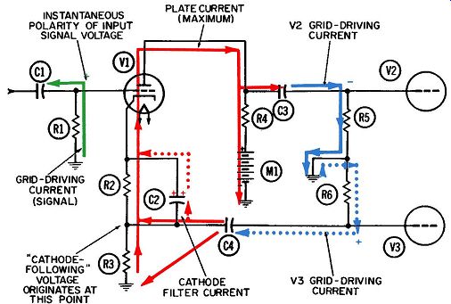
Fig. 1. Operation of a cathode-follower phase-inverter circuit-first half-cycle.
The currents, and the colors indicating them, in this circuit are:
1. Grid-driving current for V1 (green).
2. Plate current (solid red).
3. Grid-driving current for V2 (solid blue).
4. Grid-driving current for V3 ( dotted blue) .
5. Cathode filter current (dotted red). In addition to these currents, it is always possible, and some times inevitable, that grid leakage current will flow from any vacuum tube. Because the grid-leakage phenomenon is not used in this particular circuit, grid-leak currents have not been shown in the diagrams of Figs. 1 and 2. However, all tube circuits in variably take care of any grid-leakage electrons by having a closed path back to ground and the cathode from the grid. This path may consist of a single resistor or any number of such components in combination, as long as grid-leakage electrons have a path available through which they can return to the cathode of the tube from which they were emitted. In Figs. 1 and 2, this path is provided by R1 between the grid and ground, then through R3 and R2 to the cathode.
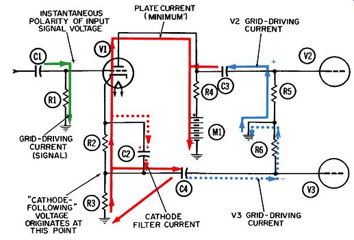
Fig. 2. Operation of a cathode-follower phase-inverter circuit-second half-cycle.
Also not shown, nor seldom referred to in discussions of circuit operation, are the cathode heating currents. These current, which frequently go by the name of filament ( or filament heating) currents, were discussed more fully in the opening Section. They perform the essential function of heating the tube cathodes so that electron emission can occur.
The remaining currents, which might be termed "operating" ones, are shown in Figs. 1 and 2. The initial, or input, function in this circuit is that of driving the grid of tube V1. This action is provided by the electron current (in green) as it flows upward through grid resistor R1 during the first half-cycle depicted by Fig. 1. The current here is, in all probability, being driven by the plate-current and -voltage combination of a preceding voltage amplifier stage.
When current is being drawn upward and onto the right plate of capacitor C1, this indicates a positive voltage at the top of resistor R1. The voltage, indicated by a plus sign, is also applied to the control grid of tube V1, releasing a large pulsation of electron current into the plate circuit of the tube. This plate current (in solid red) flows onto the left plate of coupling capacitor C3, driving another current downward through grid resistor R5. This is the grid driving current for tube V2, and is shown in solid blue.
Its complete path lies between coupling capacitor C3 and the ground connection at the bottom of R5. Its downward direction during this first half-cycle tells us the voltage at the top of resistor R5 has to be negative. This negative voltage is indicated by a minus sign, to show the instantaneous polarity of the grid voltage.
Since the polarity at the grid of tube V1 is positive during this first half-cycle, we see that the signal has experienced the normal phase reversal in its passage from the first to the second tube.
The Cathode-Follower Principle
The complete path of the plate current, shown by the solid red lines, is from cathode to plate, downward through load resistor R4, through power supply Ml and into the common ground connection. The plate current then has free access to the cathode by being drawn upward through cathode biasing resistors R3 and R2.
By virtue of the electrons which have left the cathode and gone across the tube to the plate, the voltage at the top of these two resistors will be positive with respect to ground, and it is this positive voltage which draws electrons up from ground and completes the plate-current path. If no bypass capacitor were present, this positive cathode voltage would increase as the plate current increased during the positive half-cycles, and would de crease during the negative half-cycles as the plate current de creased. This phenomenon is known as degeneration.
Capacitor C2 is used for filtering purposes across R2 in order to keep the voltage drop across R2 constant and thereby prevent degeneration across this resistor. A certain amount of degeneration will occur across remaining cathode resistor R3, however, for the following reason. As the plate current through V1 increases, the positive voltage at the top of resistor R3 will rise accordingly, because of the Ohm's law relationship between the value of the resistor, the amount of current, and the resulting voltage across the resistor.
Capacitor C4 couples this rise in positive voltage to the control grid of the lower push-pull tube, V3. This action can be visualized by looking at the currents flowing in and out of C4.
As the positive voltage at the top of R3 increases, it will tend to draw electrons away from the left plate of C4. Their departure draws an equal number of electrons onto the right plate of C4.
This electron flow, shown in dotted blue, constitutes the grid driving current for the lower push-pull tube, V3. Their downward flow through grid resistor R6 indicates that the voltage at the bottom of R6 will have a positive polarity (indicated by the blue plus sign) since electrons will always flow away from an area of negative voltage and toward an area of positive voltage. This is the positive grid voltage for tube V3.
When an alternating voltage is taken, or "coupled," from it, the cathode will have the same polarity as the input or driving voltage. In the example of Fig. 1, the moment the grid voltage reaches its most positive value, the voltage across the lower cathode resistor, R3, will also reach its most positive value and be coupled to the grid of the next tube, making the grid positive.
This function is known as cathode following which means the voltage coupled out of the cathode circuit has the same polarity as the voltage at the grid of the same tube. In that sense the cathode voltage "follows'' the input voltage.
In the second half-cycle, depicted by Fig. 2, most of these conditions are reversed. The grid-drive current flows downward through resistor R1, making the control grid of tube V1 negative. As a result, the plate current through tube V1 is reduced and its plate voltage rises. This rise in plate voltage draws electron away from the left plate of C3 and causes an equal number to flow upward through R5 to the right plate of C3. The resulting voltage drop across R5 makes the grid of V2 positive as indicated by the blue plus sign.
This reduction in the current flowing upward through R3 and into the tube causes a smaller voltage drop across this resistor than occurred during the first half-cycle. This means the positive voltage at the top of resistor R3 will fall and thus permit electrons to return toward the left plate of capacitor C4. This re turn flow will be accompanied by (1) a reversal in the direction of the grid driving current flowing through resistor R6, and (2) a change in polarity, of the grid drive voltage for tube V3, from plus to minus.
Hence, it is evident that the phase of the driving signal has now been inverted-when one push-pull tube is driven positive, the other is driven negative and vice versa.
Cathode Filtering
Capacitor C2 is bridged across resistor R2 to bypass the plate current pulses around R2. It does this by alternately receiving some electrons onto its top plate during negative half-cycles such as the one in Fig. 2 and relinquishing them into the tube during positive half-cycles (Fig. 1). When electrons are given up into the tube, an equal number will be drawn onto the lower plate of the capacitor; this current is shown in dotted red. Fig. 2 shows what happens when the tube refuses to take the electrons coming up through the cathode resistors. The excess electrons flow onto the upper plate of capacitor C2 and drive an equal number away from the lower plate.
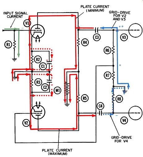
Fig. 3. Operation of a two-tube phase-inverter circuit-first half-cycle.
The small current flowing in and out of the capacitor is the cathode filter current. Its action is somewhat analogous to that of a shock absorber on an automobile-it keeps the voltage at the cathode from fluctuating with the current going into the tube.
TWO-TRIODE PHASE INVERTER
Figs. 3 and 4 depict another common type of circuit arrangement for achieving push-pull amplification at audio frequencies.
An additional driving tube is utilized, its purpose being to invert the phase of the input signal.
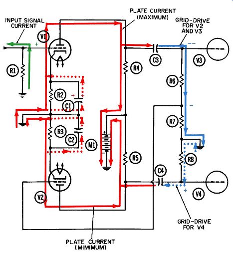
Fig. 4. Operation of a two-tube phase-inverter circuit-second half-cycle.
The components which make up this circuit are:
R1-lnput grid drive resistor.
R2-Cathode bias resistor for V1.
R3-Cathode bias resistor for V2.
R4-Plate load or coupling resistor for V1.
RS-Plate load or coupling resistor for V2.
R6-Grid drive resistor for V3.
R7-Grid drive resistor for V2 (the phase-inverting resistor).
R8-Grid drive resistor for V4.
C1--Cathode bypass capacitor for V1.
C2-Cathode bypass capacitor for V2.
C3-Coupling and blocking capacitor between V1 and V3.
C4-Coupling and blocking capacitor between V2 and V 4.
V1-lnput driving tube.
V2-lnput phase-inverting tube.
V3 and V4-Push-pull amplifier tubes.
M1--Power supply.
The currents, and the colors they are shown in are:
1. Input-signal current flowing through R1 (green).
2. Plate current for V1 (solid red).
3. Plate current for V2 (also in solid red).
4. Cathode filter currents for V1 and V2 ( dotted red).
5. Grid driving current for tubes V2 and V3 (solid blue).
6. Grid driving current for tube V4 (dotted blue).
Analysis of Operation
The grid driving current (in green) flowing through resistor R1 would in all probability be the output current of a preceding voltage-amplifier stage. During the first half-cycle depicted by Fig. 3, this current is flowing downward through R1. This tells us the top of the resistor must be more negative than the bottom, since electrons (being negative themselves) will always flow away from a more negative voltage and toward a more positive one.
This negative grid voltage is depicted by a minus sign at the top of the resistor in Fig. 3.
Throughout the entire first quarter-cycle, the grid voltage is becoming progressively more negative. Likewise, the plate cur rent through V1 is being progressively reduced. The result is that the plate current (in solid red) will have dropped to its minimum value by the end of the first quarter-cycle. Since this current must flow downward through plate load and coupling resistor R4, the voltage drop across R4 will be smaller and the plate voltage higher than at any other moment during the entire cycle.
Ordinarily, any fluctuations in plate voltage will be coupled, across capacitor C3, to the grid driving resistor for the next stage.
The change in plate voltage just described, which occurs during the first half-cycle, can only come about if more electrons are taken away from the plate than are delivered onto it. This means the positive terminal of the power supply draws more electrons downwards through plate load resistor R4 than the plate current of tube V1 is delivering. These extra electrons can only come from the left plate of capacitor C3. An equal number must then be drawn onto the right plate of the same capacitor, to compensate for the loss.
The electrons being drawn onto the right plate of C3 can only come upward through resistors R6 and R7 from the common ground connection at the bottom of R7. In flowing through R6 and R7, these electrons comprise the grid driving current for both tubes V3 and V2 and the voltage at the top of R6 becomes progressively more positive throughout the first quarter-cycle.
Recall that the grid voltage for tube V1 became progressively more negative during this same quarter-cycle. So it should be obvious the conventional phase shift or inversion from grid to plate of tube V1 has occurred. A small portion of this V3 grid driving voltage is now used to drive the grid of V2. This was the purpose in putting low-resistance R7 in series with high resistance R6. By selecting the proper values for R6 and R7, the voltage developed across R7 by the grid driving current can be made equal in value but opposite in polarity to the voltage being developed across resistor R1 by the original input-signal current.
Thus, if the voltage amplification achieved by V1 has a value of 100 (not unusual for voltage amplifiers), resistor R7 would need to be only 1/100th the value of resistor R6.
Since the control grid of V2 is connected directly to the junction of R6 and R7, the voltage at this point becomes the grid drive voltage for the tube. Thus, during the first half-cycle shown in Fig. 3, the control grid of V2 becomes progressively more positive throughout the half-cycle, causing a steady increase in the current through the tube.
We associate an increase in plate current with a decrease in the positive plate voltage applied to the plate. This decrease in voltage can only come about if more electrons are delivered into the plate area at any instant during the entire half-cycle than the power supply is drawing away. If a temporary surplus of electrons is created on the plate during this half-cycle, the only place they can accumulate is on the left plate of capacitor C4. Moreover, they cannot flow onto the left plate of C4 unless an equal number are permitted to flow away from the right plate. The electrons which flow away (actually, they are "pushed" away) from the right plate of C4 have only one path available to them, and that is upward through resistor RS to the common ground connection.
These electrons become the grid driving current for push-pull tube V4. Their amount increases steadily, or sinusoidally (since all grid driving voltages in this circuit have the same sinewave shape as the input-signal voltage) , throughout the entire first quarter-cycle of Fig. 3. Consequently the grid voltage for tube V 4 increases sinusoidally in the negative direction, causing the plate current through tube V4 to decrease from its maximum to its minimum value.
During the second half-cycle, the grid-driving currents and the resulting voltages will be reversed, as shown in Fig. 4. Current will flow upward through R1, driving the grid of V1 progressively more positive during the third quarter cycle. This increase in plate current results in a greater voltage drop across R4; hence the plate voltage for V1 will be reduced. Electrons flow onto the left plate of C3 driving an equal number off the right plate of C3 and down through R6 and R7 as shown by the solid blue line.
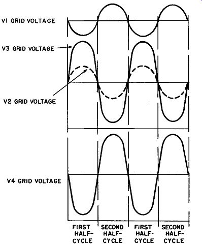
Fig. 5. Grid-voltage waveforms for the circuit in Figs. 3 and 5-4.
This electron flow drives the grid of V3 negative and the voltage at the junction of R6 and R7 will be a negative polarity but equal in value to the voltage at the grid of V1.
The negative voltage at the grid of V2 reduces the plate cur rent through this tube; hence, its plate voltage increases. This in crease in the V2 plate voltage draws electrons away from the left plate of C4 and an equal number of electrons (indicated by the dotted blue line) flow from ground, through R8, and onto the right plate of the capacitor. The flow of electrons onto the right plate of C4 becomes the grid-driving current for V 4. The grid driving voltage produced by this current through R8 is indicated by the plus sign at the grid of V4.
Thus, we have established that two sinusoidal voltages, both equal in amplitude, but 180° out of phase, are driving the two push-pull tubes. Fig. 5 shows the relationship between the four grid voltages.
The cathode filter current, indicated by the dotted red lines in Figs. 3 and 4, smooth out the fluctuations in the cathode voltages that would normally exist because of the pulsations in current through the cathode resistors. This is the same as was explained for Figs. 1 and 2, except that now we have two capacitors, and two filter currents.