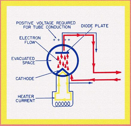
SECTION 1--BASIC VACUUM-TUBE ACTIONS
Diode Tubes-Triode Tubes-Tetrode Tubes-Pentode Tubes
SECTION 2--R-C COUPLED AF Voltage AMPLIFIERS
Circuit Description--Current Flows--Cathode Circuit--Waveform Analysis--Frequency Response--Feedback-Amplitude Distortion--Phase Distortion
SECTION 3--TRANSFORMER-COUPLED AF VOLTAGE AMPLIFIERS
Circuit Description-Transformer Action-Frequency Response- Frequency Distortion-Negative Voltage Feedback
SECTION 4--AUDIO-FREQUENCY POWER AMPLIFIERS
Transformer-Coupled Power Amplifier--Advantages of Push-Pull Operation--Push-Pull Amplifier Using Grid-Leak Bias-Push-Pull Amplifier--Using Cathode Bias-Class-B Push-Pull Amplifier
SECTION 5--AUDIO PHASE-INVERSION CIRCUITS
Single-Triode Phase Inverter-Two-Triode Phase Inverter
SECTION 6--IMPEDANCE-COUPLED RF VOLTAGE AMPLIFIERS
Untuned Impedance-Coupled Amplifier-Tuned Impedance-Coupled Amplifier-Radio-Frequency Alternating Currents-Filtering Currents-Unidirectional Currents
SECTION 7--TRANSFORMER-COUPLED RF VOLTAGE AMPLIFIERS
Untuned-Primary-Tuned-Secondary Coupling-Tuned-Primary Tuned-Secondary Coupling--The Bandpass Amplifier- Series Versus Parallel Impedance
This is the second volume in the "Basic Electronic Series." While the content of this guide does not depend on information contained in the previous Oscillator Circuits volume, readers with little or no background in electronics will find its discussion on electronic fundamentals helpful in understanding certain basic principles. However, it is not absolutely necessary to refer to the previous volume, since each circuit discussion in this guide includes a complete description of the major electronic actions.
The same approach and analysis is used in describing the circuits in all guides of this series. This approach consists first of clearly and unmistakably identifying every electron current at work in a circuit, and then of carrying out a detailed discussion of the movements of each current as well as the significance of these movements.
The circuit diagrams in this guide treat electron currents as "moving parts." In any mechanical device, movements can be visualized and the motions of each part related to those of adjacent parts. The fact that these physical actions can be seen makes it easier to understand how the device works. Surprisingly, the same analytical technique can be adopted to explain electronic circuit actions. The ability to visualize the movements of electron currents is basic to a genuine understanding of all circuit operations.
In addition, it will provide the background needed to understand the more advanced forms of circuit theory.
There are several ways amplifiers can be classified. The method in this guide is the one most generally accepted; it is organized around the three broad groups of amplifiers likely to be encountered by the newcomer to electronics. These groups are:
Audio-frequency voltage amplifiers.
Audio-frequency power amplifiers.
Radio-frequency voltage amplifiers.
The study of amplification naturally includes the means by which voltages and currents are coupled from one circuit to an other. The three most common means of coupling--resistance capacitance, impedance, and transformer--are the bases for further division of the three broad groups of amplifiers into Sections.
Feedback, both positive and negative, is closely associated with audio systems. It, too, has been analyzed by means of examples in the appropriate places. The reader who can understand how these circuits work is well-equipped to study more advanced applications of amplification. Because of the emphasis which has been placed on the guide's primary object of explaining how circuits operate, and also because of its simplified approach, this material is considered neither too advanced for high-school students, nor too elementary for those at a college level.
The author is indebted to the same individuals named in the preface of the oscillator text for their valuable time in looking at some of the original drawings and for making various helpful suggestions.
Also see:
Vacuum Tube high-fidelity in Mono: design, construction and measurements