9. DVD and CD readout in detail
The CD medium is designed to be read with a phase contrast microscope, and so it is correct to describe the deformities on the information layer as a phase structure. The original LaserVision disk patent 7 contains a variety of approaches, but in the embodiment used in CD it consists of two parallel planes separated by a distance which is constant and specifically related to the wavelength of the light which will be used to read it. The phase structure is created with deformities which depart from the first of the planes and whose extremities are in the second plane. These deformities are called pits when the second plane is below the first and bumps when the second plane is above the first.
Whilst a phase structure can be read by transmission or reflection, commercial designs based the Philips medium, such as LaserVision, 8 DVD, CD, CD-Video, CDROM and prerecorded MiniDisc, use reflective readout exclusively.
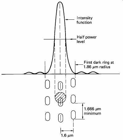
FIG. 26 The structure of a maximum frequency recording is shown here,
related to the intensity function of an objective of 0.45NA with 780nm light.
Note that track spacing puts adjacent tracks in the dark rings, reducing crosstalk.
Note also that as the spot has an intensity function it is meaningless to specify
the spot diameter without some reference such as an intensity level.
Optical physicists characterize materials by their reflectivity, transmissivity and absorption. Light energy cannot disappear, so when light is incident on some object, the amounts of light transmitted, absorbed and reflected must add up to the original incident amount. When no light is absorbed, the incident light is divided between that transmitted and that reflected. When light is absorbed, the transmitted and reflected amounts of light are both reduced. A medium such as a photograph contains pigments which absorb light more in the dark areas and less in the light areas. Thus the amount of light reflected varies. A medium such as a transparency also contains such pigments but in this case it is primarily the amount of light transmitted which varies. Such a variation in transmitted or reflected light from place to place is known as contrast.
FIG. 2(a) showed that in CD, the information layer consists of an optically flat surface above which flat-topped bumps project. The entire surface of the phase structure is metallized to render it reflective. This metallization of the entire information layer means that little light is transmitted or absorbed, and as a result virtually all incident light must be reflected. The information layer of CD does not have conventional contrast. Contrast is in any case unnecessary as interference is used for readout, and this works better with a totally reflecting structure.
Referring to FIG. 26 it will be seen that a spot of light is focused onto the phase structure such that it straddles a bump. Ideally half the light energy should be incident on the top of the bump and half on the surrounding mirror surface. The height of the bump is ideally one quarter the wavelength of the light in a reflective system and as a result light which has reflected from the mirror surface has travelled one half a wavelength further than light which has reflected from the mirror surface. Consequently, along the normal, there are two components of light of almost equal energy, but they are in phase opposition, and destructive interference occurs, such that no wavefront can form in that direction. As light energy cannot disappear, wavefronts will leave the phase structure at any oblique angle at which constructive interference between the components can be achieved, creating a diffraction pattern.
In the case of the light beam straddling the center of a long bump the diffraction pattern will be in a plane which is normal to the disk surface and which intersects a disk radius. It is thus called a radial diffraction pattern. The zeroth-order radiation (that along the normal) will be heavily attenuated, and most of the incident energy will concentrated in the first- and second-order wavefronts.
Some treatments use the word scattering to describe the effect of the interaction of the readout beam with the relief structure. This is technically incorrect as scattering is a random phenomenon which is independent of wavelength. The diffraction pattern is totally predictable and strongly wavelength dependent.
When the light spot is focused on a plain part of the mirror surface, known as a land, clearly most of the energy is simply reflected back whence it came. Thus when a bump is present, light is diffracted away from the normal, whereas in the absence of a bump, it returns along the normal. Although all incident light is reflected at all times, the effect of diffraction is that the direction in which wavefronts leave the phase structure is changed by the presence of the bump. What then happens is a function of the optical system being used. In a conventional CD player the angle to the normal of the first diffracted order in the radial diffraction pattern due to a long bump will be sufficiently oblique that it passes outside the aperture of the objective and does not return to the photosensor. Thus the bumps appear dark to the photosensor and the lands appear bright. Although all light is reflected at all times and there is no conventional contrast, inside the pickup there are variations in the light falling on the photosensor, a phenomenon called phase contrast.
The phase contrast technique described will only work for a given wavelength and with an appropriate aperture and lens design, and so the CD must be read with monochromatic light. Whilst the ideal case is where the two components of light are equal to give exact cancellation, in practice this ideal is not met but instead there is a substantial reduction in the light returning to the pickup.
Some treatments of CD refer to a 'beam' of light returning from the disk to the pickup, but this is incorrect. What leaves the disk is a hemispherical diffraction pattern certain orders of which enter the aperture of the pickup. The destructive interference effect can be seen with the naked eye by examining any CD under a conventional incandescent lamp. The data surface of a CD has many parallel tracks and works somewhat like a diffraction grating by dispersing the incident white light into a spectrum.
However, the resultant spectrum is not at all like that produced by a conventional diffraction grating or by a prism. These latter produce a spectrum in which the relative brightness of the colors is like that of a rainbow, i.e. the green in the center is brightest, the red at one end is less bright and the blue at the other end is fainter still. This is due to the unequal response of the eye to various colors, where equal red, green and blue stimuli produce responses in approximately the proportions 2:5:1 respectively. In the diffracted spectrum from a CD, however, the blue component appears as strong or stronger than the other colors. This is because the relief structure of CD is designed not to reflect infrared light of 780 nm wavelength. This relief structure will, however, reflect perfectly ultraviolet light of half that wavelength as the zeroth-order light reflected from the top of the bumps will be in phase with light reflected from the land. Thus a CD reflects visible blue light much more strongly than longer-wavelength colors.
It is essential to the commercial success of CD that a useful playing time (75min max.) should be obtained from a recording of reasonable size (12 cm). The size was determined by the European motor industry as being appropriate for car dashboard-mounted units. It follows that the smaller the spot of light which can be created, the smaller can be the deformities carrying the information, and so more information per unit area (known in the art as the superficial recording density) can be stored.
Development of a successful high-density optical recorder requires an intimate knowledge of the behavior of light focused into small spots. If it is attempted to focus a uniform beam of light to an infinitely small spot on a surface normal to the optical axis, it will be found that it is not possible. This is probably just as well as an infinitely small spot would have infinite intensity and any matter it fell on would not survive. Instead the result of such an attempt is a distribution of light in the area of the focal point which has no sharply defined boundary. This is called the Airy distribution9 (sometimes pattern or disk) after Lord Airy (1835), the then astronomer royal. If a line is considered to pass across the focal plane, through the theoretical focal point, and the intensity of the light is plotted on a graph as a function of the distance along that line, the result is the intensity function shown in FIG. 26. It will be seen that this contains a central sloping peak surrounded by alternating dark rings and light rings of diminishing intensity. These rings will in theory reach to infinity before their intensity becomes zero. The intensity distribution or function described by Airy is due to diffraction effects across the finite aperture of the objective. For a given wavelength, as the aperture of the objective is increased, so the diameter of the features of the Airy pattern reduces. The Airy pattern vanishes to a singularity of infinite intensity with a lens of infinite aperture which, of course, cannot be made. The approximation of geometric optics is quite unable to predict the occurrence of the Airy pattern.
An intensity function does not have a diameter, but for practical purposes an effective diameter typically quoted is that at which the intensity has fallen to some convenient fraction of that at the peak. Thus one could state, for example, the half-power diameter.
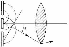
FIG. 27 Fine detail in an object can only be resolved if the diffracted
wavefront due to the highest spatial frequency is collected by the lens. Numerical
aperture (NA) = sin θ, and as θ is the diffraction angle it follows
that, for a given wavelength, NA determines resolution.
Since light paths in optical instruments are generally reversible, it is possible to see an interesting corollary which gives a useful insight into the readout principle of CD. Considering light radiating from a phase structure, as in FIG. 27, the more closely spaced the features of the phase structure, i.e. the higher the spatial frequency, the more oblique the direction of the wavefronts in the diffraction pattern which results and the larger the aperture of the lens needed to collect the light if the resolution is not to be lost. The corollary of this is that the smaller the Airy distribution it is wished to create, the larger must be the aperture of the lens. Spatial frequency is measured in lines per millimeter and as it increases, the wavefronts of the resultant diffraction pattern become more oblique. In the case of a CD, the smaller the bumps and the spaces between them along the track, the higher the spatial frequency, and the more oblique the diffraction pattern becomes in a plane tangential to the track. With a fixed-objective aperture, as the tangential diffraction pattern becomes more oblique, less light passes the aperture and the depth of modulation transmitted by the lens falls. At some spatial frequency, all the diffracted light falls outside the aperture and the modulation depth transmitted by the lens falls to zero. This is known as the spatial cut-off frequency. Thus a graph of depth of modulation versus spatial frequency can be drawn and which is known as the modulation transfer function (MTF). This is a straight line commencing at unity at zero spatial frequency (no detail) and falling to zero at the cut-off spatial frequency (finest detail). Thus one could describe a lens of finite aperture as a form of spatial low-pass filter. The Airy function is no more than the spatial impulse response of the lens, and the concentric rings of the Airy function are the spatial analog of the symmetrical ringing in a phase-linear electrical filter. The Airy function and the triangular frequency response form a transform pair10 as shown in Section 3.
When an objective lens is used in a conventional microscope, the MTF will allow the resolution to be predicted in lines per millimeter. However, in a scanning microscope the spatial frequency of the detail in the object is multiplied by the scanning velocity to give a temporal frequency measured in Hertz. Thus lines per millimeter multiplied by millimeters per second gives lines per second. Instead of a straight-line MTF falling to the spatial cut-off frequency, a scanning microscope has a temporal frequency response falling to zero at the optical cut-off frequency. Whilst this concept requires a number of idiomatic terms to be assimilated at once, the point can be made clear by a simple analogy. Imagine the evenly spaced iron railings outside a schoolyard. These are permanently fixed, and can have no temporal frequency, yet they have a spatial frequency which is the number of railings per unit distance. A small boy with a stick takes great delight in running along the railings so that his stick hits each one in turn and makes a great noise. The rate at which his stick hits the railings is the temporal frequency which results from their being scanned.
This rate would increase if the boy ran faster, but it would also increase if the rails were closer together. As a consequence it can be seen that the temporal frequency is proportional to the spatial frequency multiplied by the scanning speed. Put more technically, the frequency response of an optical recorder is the Fourier transform of the Airy distribution of the readout spot multiplied by the track velocity.
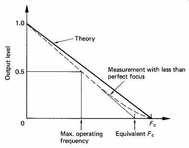
FIG. 28 Frequency response of laser pickup. Maximum operating frequency
is about half of cut-off frequency Fc.
In magnetic recorders and vinyl disk recorders there is at least a frequency band where the response is reasonably flat. CD is basically a phase contrast scanning microscope. FIG. 28 shows that the frequency response falls progressively from DC to the optical cutoff frequency which is given by:
Fc = 2NA/wavelength x velocity
The minimum linear velocity of CD is 1.2m/s, giving a cutoff frequency of:
Fc = 2 x 0.45 x 1.2/780 x 10^-9 = 1.38MHz
Actual measurements reveal that the optical response is only a little worse than the theory predicts. This characteristic has a large bearing on the type of modulation schemes which can be successfully employed.
Clearly, to obtain any noise immunity, the maximum operating frequency must be rather less than the cutoff frequency. The maximum frequency used in CD is 720 kHz, which represents an absolute minimum wavelength of 1.666 um, or a bump length of 0.833 um, for the lowest permissible track speed of 1.2m/s used on the full-length 75min-playing disks. One-hour-playing disks have a minimum bump length of 0.972m at a track velocity of 1.4m/s. The maximum frequency is the same in both cases. This maximum frequency should not be confused with the bit rate of CD since this is different owing to the channel code used. FIG. 26 showed a maximum-frequency recording, and the physical relationship of the intensity function to the track dimensions.
In a CD player, the source of light is a laser, and this does not produce a beam of uniform intensity. It is more intense in the center than it is at the edges, and this has the effect of slightly increasing the half-power diameter of the intensity function. The effect is analogous to the effect of window functions in FIR filters (see Section 3). The intensity function can also be enlarged if the lens used suffers from optical aberrations. This was studied by Marechal [11] who established criteria for the accuracy to which the optical surfaces of the lens should be made to allow the ideal Airy distribution to be obtained. CD player lenses must meet the Marechal criterion. With such a lens, the diameter of the distribution function is determined solely by the combination of numerical aperture (NA) and the wavelength. When the size of the spot is as small as the NA and wavelength allow, the optical system is said to be diffraction limited.
FIG. 27 showed how numerical aperture is defined, and illustrates that the smaller the spot needed, the larger must be the NA. Unfortunately the larger the NA, the more obliquely to the normal the light arrives at the focal plane and the smaller the depth of focus will be. This was investigated by Hopkins, 12 who established the depth of focus available for a given NA. CD players have to use an NA of 0.45 which is a compromise between a small spot and an impossibly small depth of focus. [13]
The later DVD uses an NA of 0.6 in conjunction with a shorter wavelength laser. This allows a significant reduction in the size of the recorded bumps and a corresponding increase in storage density.
Essentially the information layer of DVD is a scaled-down CD.
The intensity function will also be distorted and grossly enlarged if the optical axis is not normal to the medium. The initial effect is that the energy in the first bright ring increases strongly in one place and results in a secondary peak adjacent to the central peak. This is known as coma and its effect is extremely serious as the enlargement of the spot restricts the recording density. The larger the NA, the smaller becomes the allowable tilt of the optical axis with respect to the medium before coma becomes a problem. With the NA of CD this angle is less than a degree. [13]
Numerical aperture is defined as the cosine of the angle between the optical axis and rays converging from the perimeter of the lens. It will be apparent that there are many combinations of lens diameter and focal length which will have the same NA. As the difficulty of manufacture, and consequently the cost, of a lens meeting the Marechal criterion increases disproportionately with size, it is advantageous to use a small lens of short focal length, mounted close to the medium and held precisely perpendicular to the medium to prevent coma. As the lens needs to be driven along its axis by a servo to maintain focus, the smaller lens will facilitate the design of the servo by reducing the mass to be driven. It is extremely difficult to make a lens which meets the Marechal criterion over a range of wavelengths because of dispersion. The use of monochromatic light eases the lens design as it has only to be correct for one wavelength.
At the high recording density of CD, there is literally only one scanning mechanism with which all the optical criteria can be met and this is the approach known from the scanning microscope. The optical pickup is mounted in a carriage which can move it parallel to the medium in such a way that the optical axis remains at all times parallel to the axis of rotation of the medium. The latter rotates as the pickup is driven away from the axis of rotation in such a way that a spiral track on the disk is followed. The pickup contains a short focal length lens of small diameter which must therefore be close to the disk surface to allow a large NA. All high-density optical recorders operate on this principle in which the readout of the carrier is optical but the scanning is actually mechanical.
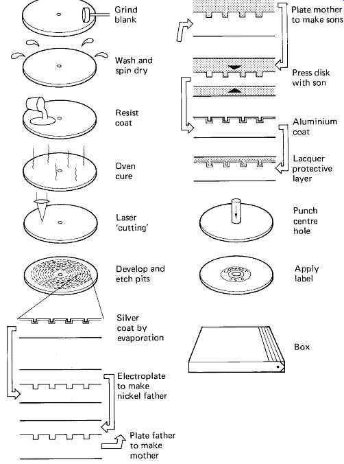
FIG. 29 The many stages of CD manufacture, most of which require the
utmost cleanliness.
10. How optical disks are made
The steps used in the production of CDs will next be outlined.
Prerecorded MiniDiscs are made in an identical fashion except for detail differences which will be noted. MO disks need to be grooved so that the track-following system will work. The grooved substrate is produced in a similar way to a CD master, except that the laser is on continuously instead of being modulated with a signal to be recorded. As stated, CD is replicated by molding, and the first step is to produce a suitable mold.
This mold must carry deformities of the correct depth for the standard wavelength to be used for reading, and as a practical matter these deformities must have slightly sloping sides so that it is possible to release the CD from the mold.
The major steps in CD manufacture are shown in FIG. 29. The mastering process commences with an optically flat glass disk about 220mm in diameter and 6mm thick. The blank is washed first with an alkaline solution, then with a fluorocarbon solvent, and spun dry prior to polishing to optical flatness. A critical cleaning process is then under taken using a mixture of de-ionized water and isopropyl alcohol in the presence of ultrasonic vibration, with a final fluorocarbon wash. The blank must now be inspected for any surface irregularities which would cause data errors. This is done by using a laser beam and monitoring the reflection as the blank rotates. Rejected blanks return to the polishing process, those which pass move on, and an adhesive layer is applied followed by a coating of positive photoresist. This is a chemical substance which softens when exposed to an appropriate intensity of light of a certain wavelength, typically ultraviolet. Upon being thus exposed, the softened resist will be washed away by a developing solution down to the glass to form flat-bottomed pits whose depth is equal to the thickness of the undeveloped resist. During development the master is illuminated with laser light of a wavelength to which it is insensitive. The diffraction pattern changes as the pits are formed. Development is arrested when the appropriate diffraction pattern is obtained. [14]
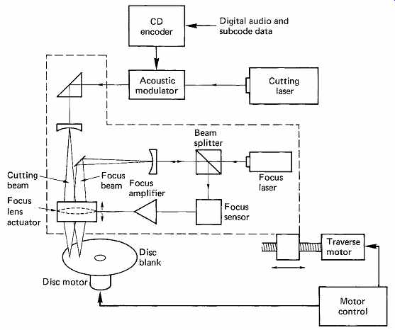
FIG. 30 CD cutter. The focus subsystem controls the spot size of the
main cutting laser on the photosensitive blank. Disc and traverse motors are
coordinated to give constant track pitch and velocity. Note that the power
of the focus laser is insufficient to expose the photoresist.
The thickness of the resist layer must be accurately controlled, since it affects the height of the bumps on the finished disk, and an optical scanner is used to check that there are no resist defects which would cause data errors or tracking problems in the end product. Blanks which pass this test are oven-cured, and are ready for cutting. Failed blanks can be stripped of the resist coating and used again.
The cutting process is shown in simplified form in FIG. 30. A continuously operating helium cadmium-15 or argon ion-16 laser is focused on the resist coating as the blank revolves. Focus is achieved by a separate helium neon laser sharing the same optics. The resist is insensitive to the wavelength of the He-Ne laser. The laser intensity is controlled by a device known as an acousto-optic modulator which is driven by the encoder.
When the device is in a relaxed state, light can pass through it, but when the surface is excited by high-frequency vibrations, light is scattered.
Information is carried in the lengths of time for which the modulator remains on or remains off. As a result the deformities in the resist produced as the disk turns when the modulator allows light to pass are separated by areas unaffected by light when the modulator is shut off. Information is carried solely in the variations of the lengths of these two areas.
The laser makes its way from the inside to the outside as the blank revolves. As the radius of the track increases, the rotational speed is proportionately reduced so that the velocity of the beam over the disk remains constant. This constant linear velocity (CLV) results in rather longer playing time than would be obtained with a constant speed of rotation. Owing to the minute dimensions of the track structure, the cutter has to be constructed to extremely high accuracy. Air bearings are used in the spindle and the laser head, and the whole machine is resiliently supported to prevent vibrations from the building from affecting the track pattern.
Early CD cutters worked in real time, but subsequently the operating speed has been increased dramatically to increase the throughput.
As the player is a phase contrast microscope, it must produce an intensity function which straddles the deformities. As a consequence the intensity function which produces the deformities in the photoresist must be smaller in diameter than that in the reader. This is conveniently achieved by using a shorter wavelength of 400-500 nm from a helium- cadmium or argon-ion laser combined with a larger lens aperture of 0.9.
These are expensive, but are only needed for the mastering process.
It is a characteristic of photoresist that its development rate is not linearly proportional to the intensity of light. This non-linearity is known as 'gamma'. As a result there are two intensities of importance when scanning photoresist; the lower sensitivity, or threshold, below which no development takes place, and the upper threshold above which there is full development. As the laser light falling on the resist is an intensity function, it follows that the two thresholds will be reached at different diameters of the function. It can be seen in FIG. 31 that advantage is taken of this effect to produce tapering sides to the pits formed in the resist. In the center, the light is intense enough to fully develop the resist right down to the glass. This gives the deformity a flat bottom. At the edge, the intensity falls and as some light is absorbed by the resist, the diameter of the resist which can be developed falls with depth in the resist. By controlling the intensity of the laser, and the development time, the slope of the sides of the pits can be controlled.
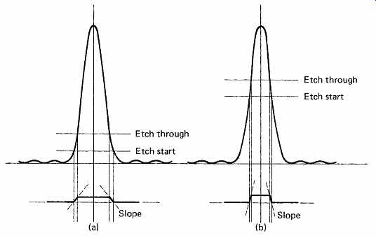
FIG. 31 The two levels of exposure sensitivity of the resist determine
the size and edge slope of the bumps in the CD. (a) Large exposure results
in large bump with gentle slope; (b) less exposure results in smaller bump
with steeper sloped sides.
In summary, the resist thickness controls the depth of the pits, the cutter laser wavelength and the NA of the objective together control the width of the pits in the radial direction, and the laser intensity and sensitivity of the resist together with the development time control the slope. The length of the pits in the tangential direction, i.e. along the track, is controlled by the speed of the disk past the objective and the length of time for which the modulator allows light to pass. The space between the pits along the track is controlled by the speed of the disk past the objective and the length of time for which the modulator blocks the laser light. In practice all these values are constant for a given cutting process except for the times for which the modulator turns on or off. As a result pits of constant depth and cross-section are formed, and only their length and the space between them along the track is changed in order to carry information.
The specified wavelength of 780 nm and the numerical aperture of 0.45 used for playback results in an Airy function where the half-power level is at a diameter of about 1m. The first dark ring will be at about 1.9 m diameter. As the illumination follows an intensity function, it is really meaningless to talk about spot size unless the relative power level is specified. The analogy is quoting frequency response without dB limits.
Allowable crosstalk between tracks then determines the track pitch. The first ring outside the central disk carries some 7 percent of the total power, and limits crosstalk performance. The track spacing is such that with a slightly defocused beam and a slight tracking error, crosstalk due to adjacent tracks is acceptable. Since aberrations in the objective will increase the spot size and crosstalk, the CD specification requires the lens to be within the Marechal criterion. Clearly the numerical aperture of the lens, the wavelength of the laser, the refractive index and thickness of the disk and the height and size of the bumps must all be simultaneously specified.
The master recording process has produced a phase structure in relatively delicate resist, and this cannot be used for molding directly.
Instead a thin metallic silver layer is sprayed onto the resist to render it electrically conductive so that electroplating can be used to make robust copies of the relief structure. This conductive layer then makes the resist optically reflective and it is possible to 'play' the resist master for testing purposes. However, it cannot be played by the cutter, as the beam in the cutter is too small and it would not straddle the pits. The necessary phase contrast between light energy leaving the lands and pits would not then be achieved. Unfortunately the resist master cannot be played by a normal CD pickup either, because the pits in the resist are full of air, in which the velocity (and therefore the wavelength) of light is different from the value it will have in the finished disk when the pits are filled with plastic. Thus the correct pit depth for a plastic disk is incorrect in air; a third type of optical system is needed to test play a resist master in which the wavelength is shorter than the wavelength used in the normal player. This would produce an Airy pattern which was too small with a conventional lens aperture, and so a lens of smaller aperture is needed to produce a spot of the correct diameter from the 'wrong' wavelength.
The electrically conductive resist master is then used as the cathode of an electroplating process where a first layer of metal is laid down over the resist, conforming in every detail to the relief structure thereon. This metal layer can then be separated from the glass and the resist is dissolved away and the silver is recovered leaving a laterally inverted phase structure on the surface of the metal, in which the pits in the photoresist have become bumps in the metal. From this point on, the production of CD is virtually identical to the replication process used for vinyl disks, save only that a good deal more precision and cleanliness is needed.
This first metal layer could itself be used to mold disks, or it could be used as a robust submaster from which many stampers could be made by pairs of plating steps. The first metal phase structure can itself be used as a cathode in a further electroplating process in which a second metal layer is formed having a mirror image of the first. A third such plating step results in a stamper. The decision to use the master or substampers will be based on the number of disks and the production rate required.
The master is placed in a molding machine, opposite a flat plate. A suitable quantity of molten plastic is injected between, and the plate and the master are forced together. The flat plate renders one side of the disk smooth, and the bumps in the metal stamper produce pits in the other surface of the disk. The surface containing the pits is next metallized, with any good electrically conductive material, typically aluminum. This metallization is then covered with a lacquer for protection. In the case of CD, the label is printed on the lacquer. In the case of a prerecorded MiniDisc, the ferrous hub needs to be applied prior to fitting the cartridge around the disk.
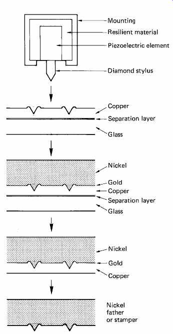
FIG. 32 In direct metal mastering, a piezoelectric element embosses a
copper layer, which is plated over with nickel and subsequently etched away
to make a father, or for direct use as a stamper for short runs.
11. Direct metal mastering
An alternative method of CD duplication has been developed by Teldec. [17]
As FIG. 32 shows, the recording process is performed by a diamond stylus which embosses the pit structure into a thin layer of copper. The stylus is driven by a piezoelectric element using motional feedback. The element is supported in an elastic medium so that its own center of gravity tends to remain stationary. Application of drive voltage makes the element contract, lifting the stylus completely off the copper between pits.
Since the channel code of CD is DC-free, the stylus spends exactly half its time in contact with the copper, and therefore the embossing force is exactly twice the static force applied. The pits produced are vee-shaped, rather than the flat-bottomed type produced by the photoresist method, but this is not of much consequence, since the diffraction-limited optics of the player cannot determine any more about the pit than its presence or absence. It is claimed that this form of pit is easier to mold.
A glass master disk is prepared as before, and following a thin separation layer, a coating of copper about 300 nm thick is sputtered on.
The recording is made on this copper layer, which is then gold-coated, and nickel-plated to about 0.25mm thick. The resultant metal sandwich can then be peeled off the glass master, which can be re-used. The recording is completely buried in the sandwich, and can be stored or transported in this form.
In order to make a stamper, the copper is etched away with ferric chloride to reveal the gold-coated nickel. This can then be used as an electroplating father, as before. For short production runs, the nickel layer can be used as a stamper directly, but it is recommended that the gold layer be replaced by rhodium for this application.
12. MiniDisc read/write in detail
MiniDisc has to operate under a number of constraints which largely determine how the read/write pickup operates. A prerecorded MiniDisc has exactly the same track dimensions as CD so that it can be mastered on similar equipment. When playing a prerecorded disk, the MiniDisc player pickup has to act in the same way as a CD pickup. This determines the laser wavelength, the NA of the objective and the effective spot diameter on the disk. This spot diameter must also be used when the pickup is operating with an MO disk.
FIG. 33(a) shows to scale a CD track being played by a standard pickup. The readout spot straddles the track so that two antiphase components of reflected light can be obtained. As was explained in section 12.10, the CD mastering cutter must use a shorter wavelength and larger NA than the subsequent player in order to 'cut' the small pits in the resist. FIG. 33(b) shows that the cutting process convolves the laser enabling pulse with the spot profile so that the pit is actually longer than the pulse duration by a spot diameter. The effect is relatively small in CD because of the small spot used in the cutter.
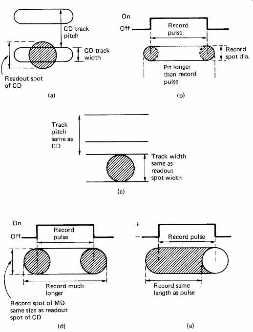
FIG. 33 (a) A CD track and readout spot to scale. (b) The CD track is
cut by a smaller spot, but the process results in pits which are longer than
the pulse duration. (c) An MO track and readout spot to scale. If this spot
is pulsed for writing, the magnetized areas are much larger than the pulse period
and density is compromised as in (d). If, however, the magnetic field is modulated,
as in (e), the recording is made at the trailing edge of the spot and short wavelengths
can be used.
When using an MO disk, the tracks recorded will be equal in width to the spot diameter and so will be wider than CD tracks as FIG. 33(c) shows. MO writing can be performed in two ways. The conventional method used in computer disks is to apply a steady current to the coil and to modulate the laser. This is because the coil has to be some distance from the magnetic layer of the disk and must be quite large. The inductance of the coil is too great to allow it to be driven at the data frequency in computer applications.
FIG. 33(d) shows what would happen if MD used laser modulation. The spot profile is convolved with the modulation pulse as for a CD cutter, but the spot is the same size as a replay spot. As a result the magnetized area is considerably longer than the modulation pulse. The shortest wavelengths of a recording could not be reproduced by this system, and it would be necessary to increase the track speed, reducing the playing time.
The data rate of MiniDisc is considerably lower than is the case for computer disks, and it is possible to use magnetic field modulation instead of laser modulation. The laser is then on continuously, and the spot profile is no longer convolved with the modulation. The recording is actually made at the instant the magnetic layer cools below the Curie temperature of about 180°C just after the spot has passed. The state of the magnetic field at this instant is preserved on the disk. FIG. 33(e) shows that the recorded wavelength can be much shorter because the recording is effectively made by the trailing edge of the spot. This makes the ends of the recorded flux patterns somewhat crescent-shaped. Thus a spot the same size as a CD readout spot can be made to record flux patterns as short as the pits made by the smaller spot of a cutter. The recordable MiniDisc can thus have the same playing time as a prerecorded disk. The optical pickup is simplified because no laser modulator is needed.
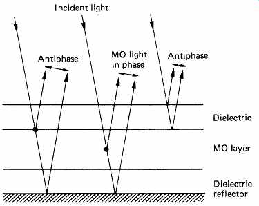
FIG. 34 In MO disks the dielectric and reflective layers are as important
as the magneto-optic layer itself.
The magnetic layer of MO disks should show a large Kerr rotation angle in order to give an acceptable SNR on replay. A high Curie temperature requires a high recording power, but allows greater readout power to be used without fear of demagnetization. This increases the readout signal with respect to the photodiode noise. As a result the Curie temperature is a compromise. Magnetic layers with practical Curie temperatures are made from proprietary alloys of iron, cobalt, platinum, terbium, gadolinium and various other rare earths. These are all highly susceptible to corrosion in air and are also incompatible with the plastics used for molded substrates. The magnetic layer must be protected by sandwiching it between layers of material which require to be impervious to corrosive ions but which must be optically transmissive. Thus only dielectrics such as silicon dioxide or aluminum nitride can be used.
The disk pickup is concerned with analyzing light which has returned from within the MO layer as only this will have the Kerr rotation.
Reflection from the interface between the MO layer and the dielectric overlayer will have no Kerr rotation. The optical characteristics of the dielectric layers can be used to enhance readout by reducing the latter reflection. FIG. 34 shows that the MO disks have an optically reflective layer behind the sandwiched MO layer. The thickness of the dielectric between the MO layer and the reflector is selected such that light from the reflector is antiphase with light from the overlayer/MO layer interface and instead of being reflected back to the pickup is absorbed in the MO layer. Conversely, light originating in the MO layer and leaving in the direction of the pickup experiences constructive interference with reflected components of that light. These components which contain Kerr rotation are readily able to exit the disk. These measures enhance the ratio of the magneto-optic component to ordinary light at the pickup.