13. How recordable MiniDiscs are made
Recordable MiniDiscs make the recording as flux patterns in a magnetic layer. However, the disks need to be pre-grooved so that the tracking systems described in section 12.7 can operate. The grooves have the same pitch as CD and the prerecorded MD, but the tracks are the same width as the laser spot: about 1.1 m. The grooves are not a perfect spiral, but have a sinusoidal waviness at a fixed wavelength. Like CD, MD uses constant track linear velocity, not constant speed of rotation. When recording on a blank disk, the recorder needs to know how fast to turn the spindle to get the track speed correct. The wavy grooves will be followed by the tracking servo and the frequency of the tracking error will be proportional to the disk speed. The recorder simply turns the spindle at a speed which makes the grooves wave at the correct frequency. The groove frequency is 75Hz; the same as the data sector rate. Thus a zero crossing in the groove signal can also be used to indicate where to start recording. The grooves are particularly important when a checker boarded recording is being replayed. On a CLV disk, every seek to a new track radius results in a different track speed. The wavy grooves allow the track velocity to be monitored as soon as a new track is reached.
The pre-grooves are molded into the plastics body of the disk when it is made. The mold is made in a similar manner to a prerecorded disk master, except that the laser is not modulated and the spot is larger. The track velocity is held constant by slowing down the resist master as the radius increases, and the waviness is created by injecting 75Hz into the lens radial positioner. The master is developed and electroplated as normal in order to make stampers. The stampers make pre-grooved disks which are then coated by vacuum deposition with the MO layer, sandwiched between dielectric layers. The MO layer can be made less susceptible to corrosion if it is smooth and homogeneous. Layers which contain voids, asperities or residual gases from the coating process present a larger surface area for attack. The life of an MO disk is affected more by the manufacturing process than by the precise composition of the alloy.
Above the sandwich an optically reflective layer is applied, followed by a protective lacquer layer. The ferrous clamping plate is applied to the center of the disk, which is then fitted in the cartridge. The recordable cartridge has a double-sided shutter to allow the magnetic head access to the back of the disk.
14. Channel code of CD and MiniDisc
CD and MiniDisc use the same channel code known as EFM. This was optimized for the optical readout of CD and prerecorded MiniDisc, but is also used for the recordable version of MiniDisc for simplicity. DVD uses a refinement of the CD code called EFM+.
The frequency response falling to the optical cut-off frequency is only one of the constraints within which the modulation scheme has to work.
There are a number of others. In all players the tracking and focus servos operate by analyzing the average amount of light returning to the pickup.
If the average amount of light returning to the pickup is affected by the content of the recorded data, then the recording will interfere with the operation of the servos. Debris on the disk surface affects the light intensity and means must be found to prevent this reducing the signal quality excessively.
Optical disks are serial media which produce on replay only a single voltage varying with time. If it is attempted to simply serialize raw data, a process known as direct recording, it is not difficult to see what will happen in the case where the data are digital audio samples where the audio is muted. Upon serializing the all-zeros code for muting the serial waveform is simply a steady logical low level and in the absence of a separate clock it is impossible to tell how many zeros were present, nor in the case of CD will there be a track to follow. A similar problem would be experienced if all ones occur in the data except that a steady high logic level results in a continuous bump. In digital logic circuits it is common to have signal lines and separate clock lines to overcome this problem, but with a single signal the separate clock is not possible. A further problem with direct optical recording is that the average brightness of the track is a function of the relative proportion of ones and zeros. Focus and tracking servos cannot be used with direct recordings because the data determine the average brightness and confuse the servos. Section 6 discussed modulation schemes known as DC-free codes. If such a code is used, the average brightness of the track is constant and independent of the data bits. FIG. 35(a) shows the replay signal from the pickup being compared with a threshold voltage in order to recover a binary waveform from the analog pickup waveform, a process known as slicing. If the light beam is partially obstructed by debris, the pickup signal level falls, and the slicing level is no longer correct and errors occur. If, however, the code is DC-free, the waveform from the pickup can be passed through a high pass filter (e.g. a series capacitor) and FIG. 35(b) shows that this rejects the falling level and converts it to a reduction in amplitude about the slicing level so that the slicer still works properly. This step cannot be performed unless a DC-free code is used.
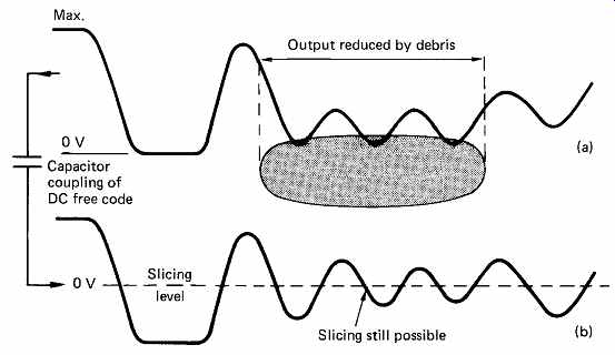
FIG. 35 A DC-free code allows signal amplitude variations due to debris
to be rejected.
As the frequency response on replay falls linearly to the cut-off frequency determined by the aperture of the lens and the wavelength of light used, the shorter bumps and lands produce less modulation than longer ones. FIG. 36(a) shows what happens to the replay waveform as a bump between two long lands is made shorter. At some point the replayed signal no longer crosses the slicing level and readout is impossible. FIG. 36(b) shows that the same effect occurs as a land between two long bumps is made shorter. In these cases recorded frequencies have to be restricted to those which produce wavelengths long enough for the player to register. Using direct recording where, for example, lands represent a 1 and bumps represent a 0 it is clear that the length of track corresponding to a one or a zero would have to be greater than the limit at which the slicing in the player failed and this would restrict the playing time.
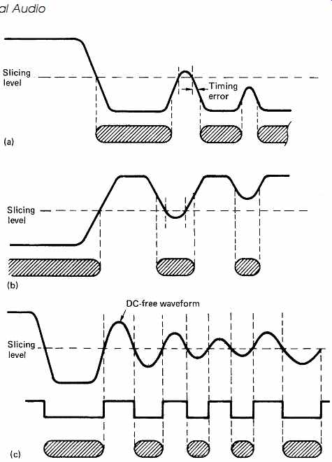
FIG. 36 If the recorded waveform is not DC-free, timing errors occur
until slicing becomes impossible. With a DC-free code, jitter-free slicing
is possible in the presence of serious amplitude variation.
FIG. 36(c) shows that if the recorded waveform is restricted to one which is DC-free, as the length of bumps and lands falls with rising density, the replay waveform simply falls in amplitude but the average voltage remains the same and so the slicer still operates correctly. It will be clear that by using a DC-free code correct slicing remains possible with much shorter bumps and lands than with direct recording. Thus in practical high-density optical disk players, including CD players, a DC free code must be used. The output of the pickup passes to two filters. A low-pass filter removes the DC-free modulation and leaves a signal which can be used for tracking, and the high-pass filter removes the effect of debris and allows the slicer to continue to function properly. Clearly direct recording of serial data from a shift register cannot be DC-free and so it cannot be read at high density, it will not be self-clocking and it will not be resistant to errors caused by debris, and it will interfere with the operation of the servos. The solution to all these problems is to use a suitable channel code. The concepts of channel coding were discussed in Section 6, in which frequency shift keying (FSK) was described. In FSK it is possible to use a larger number of different discrete frequencies, for example four frequencies allow all combinations of two bits to be conveyed, eight frequencies allow all combinations of three bits to be conveyed and so on. The channel code of CD is similar in that it is the minimal case of multi-tone FSK where only a half-cycle of each of nine different frequencies is used. These frequencies are 196, 216, 240, 270, 308, 360, 430, 540 and 720 kHz and are obtained by dividing a master clock of 2.16MHz by 11, 10, 9, 8, 7, 6, 5, 4, and 3. There are therefore nine different periods or run lengths in the CD signal, and it does not matter whether the period is the length of a land or the length of a bump. In fact the signal from a CD pickup could be inverted without making the slightest difference to the data recovery as all that is of any consequence is the time between successive zero crossings of the signal. In run-length-limited coding of this kind, the time periods are described in a relative rather than an absolute manner. Thus if half a cycle of the master clock has a period T, then the periods or run lengths of the code can be from 3T to 11T. The run lengths are combined in ways which make the resulting waveform DC-free and so the slicer will function properly as the response falls at higher frequencies. The various frequencies or periods used in CD can be seen by examining the replay waveform from the pickup with an oscilloscope. FIG. 37 shows the resultant eye pattern. It will be seen that the higher frequencies (period 3T) have the smallest amplitude on replay. Note that the optical cut-off frequency of CD is only 1.4MHz, and so it will be evident that the master clock frequency of 2.16MHz cannot be recorded or reproduced. This is of no consequence in CD as it does not need to be recorded. 1.4MHz is the frequency at which the depth of modulation has fallen to zero. As stated, the highest frequency which can be reliably recorded is about one half of the optical cut-off frequency.
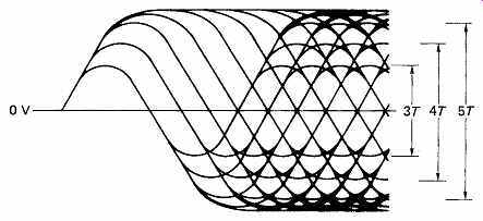
FIG. 37 The characteristic eye pattern of EFM observed by oscilloscope.
Note the reduction in amplitude of the higher-frequency components. The only
information of interest is the time when the signal crosses zero.
Frequencies above this replay with an amplitude so small that they have inadequate signal-to-noise ratio. It will be seen that the highest frequency in CD is 720 kHz which is about half of 1.4MHz. Although frequencies lower than 196kHz can be replayed easily, the clock content of lower frequencies is considered inadequate.
CD uses a coding scheme where combinations of the data bits to be recorded are represented by unique waveforms. These waveforms are created by combining various run lengths from 3T to 11T together to give a channel pattern which is 14T long. 18 Within the run length limits of 3T to 11T, a waveform 14T long can have 267 different patterns. This is slightly more than the 256 combinations of eight data bits and so eight bits are represented by a waveform lasting 14T. Some of these patterns are shown in FIG. 38. As stated, these patterns are not polarity conscious and they could be inverted without changing the meaning.
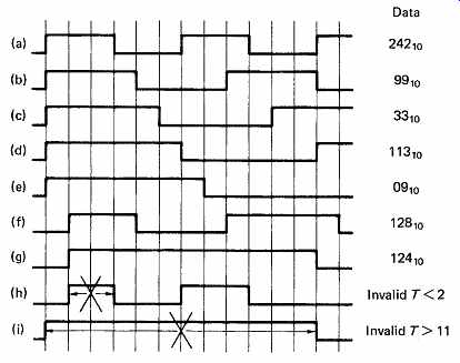
FIG. 38 (a-g) Part of the codebook for EFM code showing examples of various
run lengths from 3T to 11T. (h,i) Invalid patterns which violate the run-length
limits.
Not all the 14T patterns used are DC-free, some spend more time in one state than the other. The overall DC content of the recorded waveform is rendered DC-free by inserting an extra portion of waveform, known as a packing period, between the 14T channel patterns. This packing period is 3T long and may or may not contain a transition, which if it is present can be in one of three places. The packing period contains no information, but serves to control the DC content of the overall waveform.
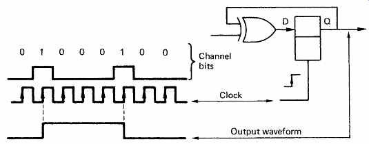
FIG. 39 A bistable is necessary to convert a stream of channel bits to
a channel-coded waveform. It is the waveform which is recorded not the channel
bits.
The packing waveform is generated in such a way that in the long term the amount of time the channel signal spends in one state is equal to the time it spends in the other state. A packing period is placed between every pair of channel patterns and so the overall length of time needed to record eight bits is 17T. Packing periods were discussed in Section 6.
CD is recorded using such patterns where the lengths of bumps and lands are modulated in ideally discrete steps. The simplest way in which such patterns can be generated is to use a look-up table which converts the data bits to a control code for a programmable waveform generator. As stated, the polarity of the CD waveform is irrelevant.
What matters on the disk are the lengths of the bumps or lands. The change of state in the signal sent to the cutter laser is called a transition.
Clearly if a bump is being cut, it will be terminated by interrupting the light beam. If a land is being recorded, it will be terminated by allowing through the light beam. Both of these are classified as a transition, therefore it is logical for the control code to cause transitions rather than to control the waveform level as it is not concerned with the polarity of the waveform. This is conveniently achieved by controlling the cutter laser with the output waveform of a JK type bistable as shown in FIG. 39. A bistable of this kind can be configured to have a data input and a clock input. If the data input is 0, there is no effect on the output when the clock edge arrives, whereas if the data input is 1 the output changes state when the clock edge arrives. The change of state causes a transition on the disk. If the clock has a period of T, at each channel time period or detent the output waveform will contain a transition if the control code is 1 or not if it is 0.
The control code is a binary word having fourteen bits which are known in the art as channel bits or binits. Thus a group of eight data bits is represented by a code of fourteen channel bits, hence the name of eight to fourteen modulation (EFM). The use of groups gives rise to the generic name of group code recording (GCR). It is a common misconception that the channel bits of a group code are recorded; in fact they are simply a convenient but not essential way of synthesizing a coded waveform having uniform time steps. It should be clear that channel bits cannot be recorded as they have a rate of 4.3Mbits/s whereas the optical cut-off frequency of CD is only 1.4MHz.
Another common misconception is that channel bits are data. If channel bits were data, all combinations of fourteen bits, or 16 384 different values could be used. In fact only 267 combinations produce waveforms which can be recorded.
In a practical CD modulator, the eight-bit data symbols to be recorded are used as the address of a look-up table which outputs a fourteen-bit channel bit pattern. As the highest frequency which can be used in CD is 720 kHz, transitions cannot be closer together than 3T and so successive 1s in the channel bit stream must have two or more zeros between them. Similarly transitions cannot be further apart than 11T or there will be insufficient clock content. Thus there cannot be more than 10 zeros between channel 1s. Whilst the look-up table can be programmed to prevent code violations within the 14T pattern, they could occur at the junction of two successive patterns. Thus a further function of the packing period is to prevent violation of the run-length limits. If the previous pattern ends with a transition and the next begins with one, there will be no packing transition and so the 3T minimum requirement can be met. If the patterns either side have long run lengths, the sum of the two might exceed 11T unless the packing period contained a transition. In fact the minimum run-length limit could be met with 2T of packing, but the requirement for DC control dictated 3T of packing.
The coding of CD may appear complex, but this is because it was designed to offer the required playing time on a disk of restricted size.
It does this by reducing the frequency of the recorded signal compared to the data frequency. Eight data bits are represented by a length of track corresponding to 17T. The shortest run length in a conventional recording code such as MFM would be the length of one bit, and as eight bits require 17T of track, the length of one bit would be 17/8T or 2.125T. Using the CD code the shortest run length is 3T. Thus the highest frequency in the CD code is less than that of an MFM recording, so a density improvement of 3/2.125 or 1.41 is obtained. Thus CD can record 41 per cent more using EFM than if it used MFM. A CD can play for 75 minutes maximum. Using MFM a CD would only play for 53 minutes.
The high-pass filtered DC-free signal from the CD pickup can be readily sliced back to a binary signal having transitions at the zero crossings. A group-coded waveform needs a suitably designed data separator to decode and deserialize the replay signal. When the disk is initially scanned, the data separator simply sees a single voltage varying with time, and it has no other information to go on whatsoever. The scanning of the disk will not necessarily be at the correct speed, and the transitions recovered will suffer from jitter. The jitter comes from two main sources. The first of these is variations in the thickness of the disk.
Everyone is familiar with the illusion that the bottom of a shallow pond is moving when there are ripples in the water. In the same way, ripples in the disk thickness make the track appear to vary in speed. The second source is simply in the production tolerance to which bump edges can be made. The replication process from master to stamper will cause some slight migration of edge position, and stampers can wear in service. In order to interpret the replay waveform in the presence of jitter, use is made of the fact that transitions ideally occur at integer multiples of T.
When a real transition occurs at a time other than an exact multiple of T, it can be attributed to the nearest multiple if the jitter is not too serious, and the jitter will be completely rejected. If, however the jitter is too great, the wrongly timed transition will be attributed to the incorrect detent, and the wrong pattern will be identified.
A phase-locked loop is an essential part of a practical high-density data separator. The operation of a phase-locked loop was described in section 5.9. If the input is a group-coded signal, it will contain transitions at certain multiples of the basic time period T, but not at every cycle owing to the run-length limits. The reason for the use of multiples of a basic time period in group codes is simply that a phase-locked loop can lock to such a waveform. When a transition occurs, a phase comparison can be made, but when no transition occurs, there is no phase comparison but the VCO will continue to run at the same frequency like a flywheel. The maximum run-length limit of 11T in CD is to ensure that the VCO does not have to run for too long between phase corrections. As a result, the VCO recreates a continuous clock from the intermittent clock content of the channel coded signal. In a group-coded system, the VCO recreates the channel bit rate. In CD this is the only way in which the channel bit rate can be reproduced, as the disk itself cannot record the channel bit rate.
Jitter in the transition timing is handled by inserting a low-pass or averaging filter between the phase detector and the VCO and/or by increasing the division ratio in the feedback. Both of these steps increase the flywheel inertia. The VCO then runs at the average frequency obtained from many channel transitions and the jitter is substantially removed from the re-created clock. With a jitter-free continuous clock available from the VCO, the actual time at which a transition occurs can differ from the ideal by a considerable amount. When the recording was made, the transitions were intended to be spaced at multiples of the channel bit period, and the run lengths in the code ideally should be discrete. In practice the analog nature of the channel causes the run lengths to vary. A certain amount of variation can be rejected in a properly engineered channel code. The VCO is used to create windows called detents along the time axis of the replay signal. An ideal jitter-free signal would have a transition in the center of the window, but real transitions may occur before or after the center. As long as the variation is within the window, it is rejected, but if the jitter were so large that a transition crossed into an adjacent window, an error would occur. It was shown in Section 6 that the jitter window of EFM is 8/17 of a data bit.
Transitions on a CD replay signal can be up to plus or minus 4/17 of a data bit period out of time before errors are caused. This jitter rejection is a requirement of the CD system because such jitter actually occurs on real disks as has been described. Indeed if it did not, the designers would have used a code with less jitter tolerance and even higher recording density. Thus it is simplistic to regard the surface of a high-density recording as a nice neat set of areas like toy bricks. In practice the manufacturing tolerances are eased so that the recording becomes cheaper even if the transitions become a little jittery. Provided the channel code can reject the jitter, the extra density makes the product more cost effective. The deformities on real CDs are not exact multiples of the basic unit in practice. If this were a requirement they could never be sold on the consumer market. The jitter-rejection mechanism allows considerable production tolerances to be absorbed so that disks can be mass produced.
The length of a deformity on a CD master is affected not only by the duration of the record pulse, which can be as accurate as necessary, but also by the sensitivity of the resist and the intensity function of the laser.
The pit which is formed in the resist is the result of the convolution of the rectangular pulse operating the modulator with the Airy function. Thus the pit will be longer than the period of the pulse would suggest. The pit edge is then subject to further position tolerance as a result of electroplating mothers and sons to create a large number of stampers. The stampers themselves will wear in service. The position of a transition is now subject to the tolerance of the cutting laser intensity function and state of focus, resist sensitivity, electroplating accuracy and wear and so the actual disk will be non-ideal.
The shortest deformity in CD is nominally 3T long or 3 x 8/17 data bits long. This can suffer nearly plus or minus 4/17 data bit periods of jitter at each end before it cannot be read properly. Thus in the worst case, where the leading edge was early and the trailing edge late, the deformity could be almost 30 per cent longer than the ideal. In typical production disks, the edge position is held a little more accurately than this theoretical limit in order to allow extra jitter in the replay process due to thickness ripple, coma due to warped disks or out-of-focus conditions.
Once the phase-locked loop has reached the lock condition, it outputs a clock whose frequency is proportional to the speed of the track. If the track speed is correct it will have the same frequency as the channel bit clock in the cutter. This clock can then be used to sample the sliced analog signal from the pickup. As can be seen from FIG. 40, transitions nominally occur in the center of a T period. If the samples are taken on the edge of every T period, a transition will be reliably detected as the difference between two successive samples even if it has positional jitter approaching plus or minus T/2. Thus the output of the sampler is a jitter free replica of the replay signal, and in the absence of errors it will be identical to the output of the JK bistable in the cutter. The sampling clock runs at the average phase of a large number of transitions from the track.
Every transition not only conveys part of the waveform representing data, but also allows the phase of the clock to be updated and so every transition can also be considered to have a synchronizing function. The 11T maximum run-length limit is necessary to ensure that synchronizing information for the VCO is regularly available in the replay waveform; a requirement that cannot be met by direct recording.
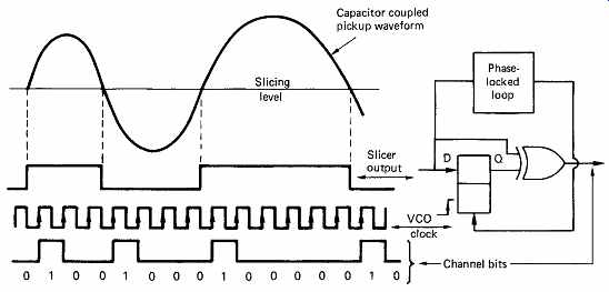
FIG. 40 The output of the slicer is sampled at the boundary of every
T period.
Where successive samples differ, a channel bit 1 is generated.
The information in the CD replay waveform is carried in the timing of the transitions, not in the polarity. It is thus necessary to create a polarity independent signal from the sliced de-jittered replay waveform. This is done by differentiating the sampler output. FIG. 40 shows that this can be achieved by a D-type latch and an exclusive-OR gate. The latch is clocked at the channel bit rate, and so acts as a one-bit delay. The gate compares the input and output of the delay. When they are the same, there is no transition and the gate outputs 0. When a transition passes through, the input and output of the latch will be different and the gate outputs 1. Thus some distance through the replay circuitry from the pickup, the channel bits reappear, just as they disappeared before reaching the cutter laser.
15. Deserialization
Decoding the stream of channel bits into data requires that the boundaries between successive 17T periods are identified. This is the process of deserialization. On the disk one 17T period runs straight into the next; there are no dividing marks. Symbol separation is performed by counting channel bit periods and dividing them by 17 from a known reference point. The three packing periods are discarded and the remaining 14T symbol is decoded to eight data bits. The reference point is provided by the synchronizing pattern which is given that name because its detection synchronizes the deserialization counter to the replay waveform.
Synchronization has to be as reliable as possible because if it is incorrect all the data will be corrupted up to the next sync pattern. Synchronization is achieved by the detection of an unique waveform periodically recorded on the track at a regular spacing. It must be unique in the strict sense in that nothing else can give rise to it, because the detection of a false sync is just as damaging as failure to detect a correct one. Clearly the sync pattern cannot be a data code value in CD as there would then be a Catch 22 situation. It would not be possible to deserialize the EFM symbols in order to decode them until the sync pattern had been detected, but if the sync pattern were a data code value, it could not be detected until the deserialization of the EFM waveform had been synchronized. Thus in a group code recording a data code value simply cannot be used for synchronizing. In any case it is undesirable and unnecessary to restrict the data code values which can be recorded; CD requires all 256 combinations of the eight-bit symbols recorded.
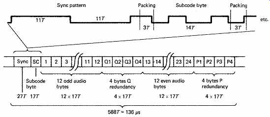
FIG. 41 One CD data block begins with a unique sync pattern, and one
subcode byte, followed by 24 audio bytes and eight redundancy bytes. Note that
each byte requires 14T in EFM, with 3T packing between symbols, making 17T.
In practice CD synchronizes deserialization with a waveform which is unique in that it is different from any of the 256 waveforms which represent data. For reliability, the sync pattern should have the best signal-to-noise ratio possible, and this is obtained by making it one complete cycle of the lowest frequency (11T plus 11T) which gives it the largest amplitude and also makes it DC-free. Upon detection of the 2 x Tmax waveform, the deserialization counter which divides the channel bit count by 17 is reset. This occurs on the next system clock, which is the reason for the 0 in the sync pattern after the third 1 and before the merging bits. CD therefore uses forward synchronization and correctly deserialized data are available immediately after the first sync pattern is detected. The sync pattern is longer than the data symbols, and so clearly no data code value can create it, although it would be possible for certain adjacent data symbols to create a false sync pattern by concatenation were it not for the presence of the packing period. It is a further job of the packing period to prevent false sync patterns being generated at the junction of two channel symbols.
Each data block or frame in CD and MD, shown in FIG. 41, consists of 33 symbols 17T each following the preamble, making a total of 588T or 136s. Each symbol represents eight data bits. The first symbol in the block is used for subcode, and the remaining 32 bytes represent 24 audio sample bytes and 8 bytes of redundancy for the error-correction system. The subcode byte forms part of a subcode block which is built up over 98 successive data frames, and this will be described in detail later in this section.
The channel bits which are re-created by sampling and differentiating the sliced replay waveform in time to the restored clock from the VCO are conveniently converted to parallel format for decoding in a shift register which need only have fourteen stages. The bit counter which is synchronized to the serial replay waveform by the detection of the sync pattern will output a pulse every 17T when a complete 14T pattern of channel bits is in the register. This pattern can then be transferred in parallel to the decoder which will identify the channel pattern and output the data code value.
Detection of sync in CD is simply a matter of identifying a complete cycle of the lowest recorded frequency. In practical players the sync pattern will be sliced, sampled and differentiated to channel bits along with the rest of the replay waveform. As a shift register is already present it is a matter of convenience to extend it to 23 stages so that the sync pattern can be detected by continuously examining the parallel output as the patterns from the track shift by. The pattern will be detected by a combination of logic gates which will only output a 'true' value when the shift register contains 10000000000100000000001 in the correct place.
This is not a bit pattern which exists on the disk; the disk merely contains two maximum run-lengths in series and it does not matter whether these are a bump followed by a land or a land followed by a bump. The sliced replay waveform cannot be sampled at the correct frequency until the VCO has locked and this requires the T rate synchronizing information from a prior length of data track. If the VCO were not locked, the sync waveform would be sampled into the wrong number of periods and would not be detected. Following sampling, the replay signal is differentiated so that transitions of either direction produce a channel bit 1.
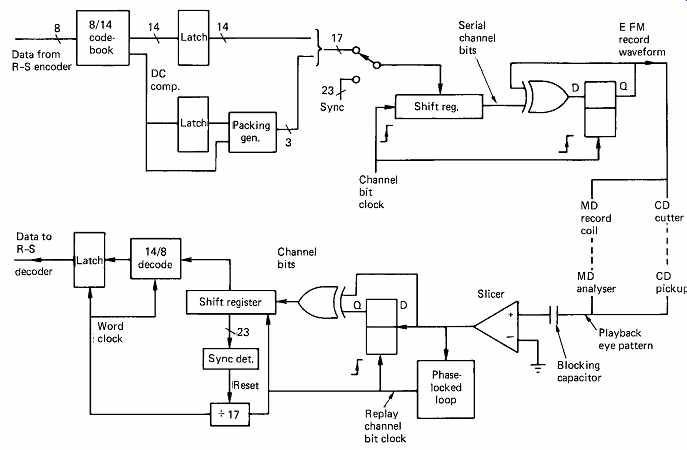
FIG. 42 Overall block diagram of the EFM encode/decode process. A MiniDisc
will contain both. A CD player only has the decoder; the encoding is in the
mastering cutter.
FIG. 42 shows an overall block diagram of the record modulation scheme used in CD mastering and the corresponding replay system or data separator. The input to the record channel coder consists of sixteen bit audio samples which are divided in two to make symbols of eight bits.
These symbols are used in the error-correction system which interleaves them and adds redundant symbols. For every twelve audio symbols, there are four symbols of redundancy, but the channel coder is not concerned with the sequence or significance of the symbols and simply records their binary code values.
Symbols are provided to the coder in eight-bit parallel format, with a symbol clock. The symbol clock is obtained by dividing down the 4.3218MHz T rate clock by a factor of 17. Each symbol is used to address the look-up table which outputs a corresponding fourteen channel bit pattern in parallel into a shift register. The T rate clock then shifts the channel bits along the register. The look-up table also outputs data corresponding to the digital sum value (DSV) of the fourteen-bit symbol to the packing generator. The packing generator determines if action is needed between symbols to control DC content. The packing generator checks for run-length violations and potential false sync patterns. As a result of all the criteria, the packing generator loads three channel bits into the space between the symbols, such that the register then contains fourteen-bit symbols with three bits of packing between them. At the beginning of each frame, the sync pattern is loaded into the register just before the first symbol is looked up in such a way that the packing bits are correctly calculated between the sync pattern and the first symbol.
A channel bit one indicates that a transition should be generated, and so the serial output of the shift register is fed to the JK bistable along with the T rate clock. The output of the JK bistable is the ideal channel coded waveform containing transitions separated by 3T to 11T. It is a self clocking, run-length-limited waveform. The channel bits and the T rate clock have done their job of changing the state of the JK bistable and do not pass further on. At the output of the JK the sync pattern is simply two 11T run lengths in series.
At this stage the run-length-limited waveform is used to control the acousto-optic modulator in the cutter. This actually results in pits which are slightly too long and lands which are too short because of the convolution of the record waveform with the Airy function which was mentioned above. As the cutter spot is about 0.4 m across, the pit edges in the resist are moved slightly. Thus although the ideal waveform is created in the encoding circuitry, having integer multiples of T between transitions, the pit structure is non-ideal and pit edges are not located at exact multiples of a basic distance. The duty cycle of the pits and lands is not exactly 50 per cent and the replay waveform will have a DC offset.
This is of no consequence in CD as the channel code is known to be DC free and an equivalent offset can be generated in the slicing level of the player such that the duty cycle of the slicer output becomes 50 per cent.
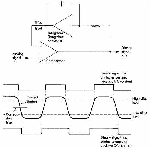
FIG. 43 Self-slicing a DC-free channel code. Since the channel code signal
from the disk is band limited, it has finite rise times, and slicing at the
wrong level (as shown here) results in timing errors, which cause the data
separator to be less reliable. As the channel code is DC-free, the binary signal
when correctly sliced should integrate to zero.
An incorrect slice level gives the binary output a DC content and, as shown here, this can be fed back to modify the slice level automatically.
The resist master is developed and used to create stampers. The resulting disks can then be replayed. The track velocity of a given CD is constant, but the rotational speed depends upon the radius. In order to get into lock, the disk must be spun at roughly the right track speed. This is done using the run-length limits of the recording. The pick-up is focused and the tracking is enabled. The replay waveform from the pick up is passed through a high-pass filter to remove level variations due to contamination and sliced to return it to a binary waveform. The slicing level is self-adapting as FIG. 43 shows, so that a 50 per cent duty cycle is obtained. The slicer output is then sampled by the unlocked VCO running at approximately T rate. If the disk is running too slowly, the longest run length on the disk will appear as more than 11T, whereas if the disk is running too fast, the shortest run length will appear as less than 3T. As a result, the disk speed can be brought to approximately the right speed and the VCO will then be able to lock to the clock content of the EFM waveform from the slicer. Once the VCO is locked, it will be possible to sample the replay waveform at the correct T rate. The output of the sampler is then differentiated and the channel bits reappear and are fed into the shift register. The sync pattern detector will then function to reset the deserialization counter which allows the 14T symbols to identified. The 14T symbols are then decoded to eight bits in the reverse coding table.
FIG. 44 reveals the timing relationships of the CD format. The sampling rate of 44.1 kHz with sixteen-bit words in left and right channels results in an audio data rate of 176.4 kb/s (k = 1000 here, not 1024). Since there are 24 audio bytes in a data frame, the frame rate will be:
176.4/24 kHz = 7.35 kHz
If this frame rate is divided by 98, the number of frames in a subcode block, the subcode block or sector rate of 75Hz results. This frequency can be divided down to provide a running-time display in the player. Note that this is the frequency of the wavy grooves in recordable MDs.
If the frame rate is multiplied by 588, the number of channel bits in a frame, the master clock-rate of 4.3218MHz results. From this the maximum and minimum frequencies in the channel, 720 kHz and 196 kHz, can be obtained using the run-length limits of EFM.
16. Error-correction strategy
This section discusses the track structure of CD in detail. The track structure of MiniDisc is based on that of CD and the differences will be noted in the next section.
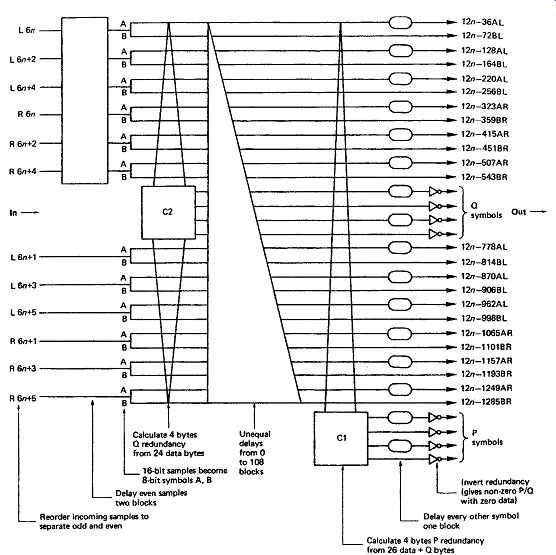
FIG. 45 CD interleave structure.
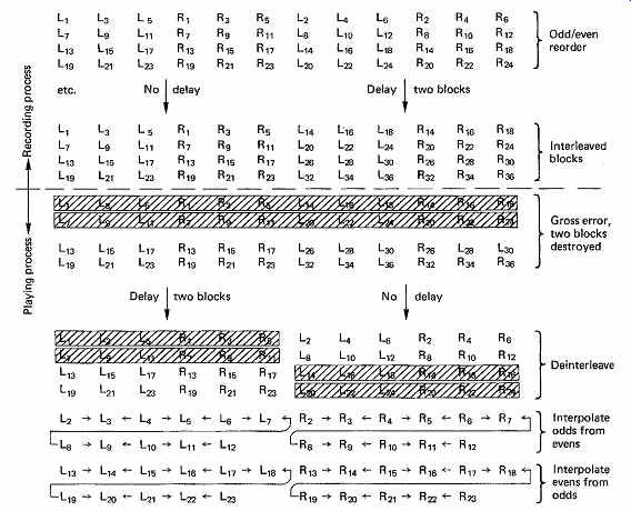
FIG. 46 Odd/even interleave permits the use of interpolation to conceal
uncorrectable errors.
Each sync block was seen in FIG. 41 to contain 24 audio bytes, but these are non-contiguous owing to the extensive interleave. [ 20-22]
There are a number of interleaves used in CD, each of which has a specific purpose.
The full interleave structure is shown in FIG. 45. The first stage of interleave is to introduce a delay between odd and even samples. The effect is that uncorrectable errors cause odd samples and even samples to be destroyed at different times, so that interpolation can be used to conceal the errors, with a reduction in audio bandwidth and a risk of aliasing. The odd/even interleave is performed first in the encoder, since concealment is the last function in the decoder. FIG. 46 shows that an odd/even delay of two blocks permits interpolation in the case where two uncorrectable blocks leave the error-correction system.
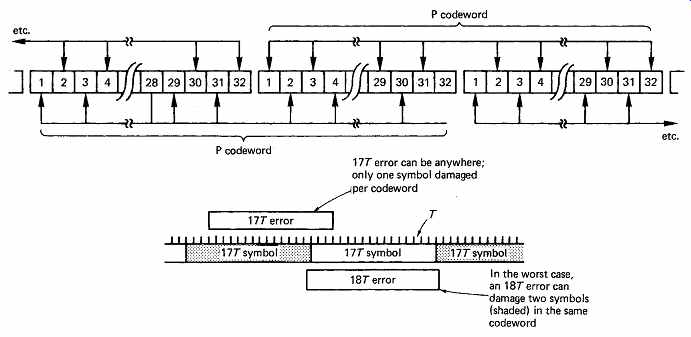
FIG. 47 The final interleave of the CD format spreads P codewords over
two blocks. Thus any small random error can only destroy one symbol in one
codeword, even if two adjacent symbols in one block are destroyed. Since the
P code is optimized for single-symbol error correction, random errors will
always be corrected by the C1 process, maximizing the burst-correcting power
of the C2 process after de-interleave.
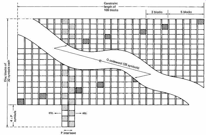
FIG. 48 Owing to cross-interleave, the 28 symbols from the Q encode process
(C2) are spread over 109 blocks, shown hatched. The final interleave of P codewords
(as in FIG. 47) is shown stippled. The result of the latter is that Q
codeword has 5, 3, 5, 3 spacing rather than 4, 4.
Left and right samples from the same instant form a sample set. As the samples are sixteen bits, each sample set consists of four bytes, AL, BL, AR, BR. Six sample sets form a 24-byte parallel word, and the C2 encoder produces four bytes of redundancy Q. By placing the Q symbols in the center of the block, the odd/even distance is increased, permitting interpolation over the largest possible error burst. The 28 bytes are now subjected to differing delays, which are integer multiples of four blocks.
This produces a convolutional interleave, where one C2 codeword is stored in 28 different blocks, spread over a distance of 109 blocks.
At one instant, the C2 encoder will be presented with 28 bytes which have come from 28 different codewords. The C1 encoder produces a further four bytes of redundancy P. Thus the C1 and C2 codewords are produced by crossing an array in two directions. This is known as cross interleaving.
The final interleave is an odd/even output symbol delay, which causes P codewords to be spread over two blocks on the disk as shown in FIG. 47. This mechanism prevents small random errors destroying more than one symbol in a P codeword. The choice of eight-bit symbols in EFM assists this strategy. The expressions in FIG. 45 determine how the interleave is calculated. FIG. 48 shows an example of the use of these expressions to calculate the contents of a block and to demonstrate the cross-interleave.
The calculation of the P and Q redundancy symbols is made using Reed-Solomon polynomial division. The P redundancy symbols are primarily for detecting errors, to act as pointers or error flags for the Q system. The P system can, however, correct single-symbol errors.
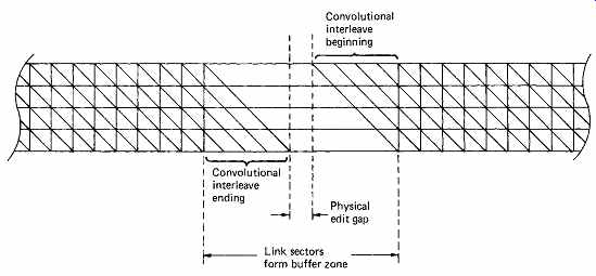
FIG. 49 The convolutional interleave of CD is retained in MD, but buffer
zones are needed to allow the convolution to finish before a new one begins,
otherwise editing is impossible.
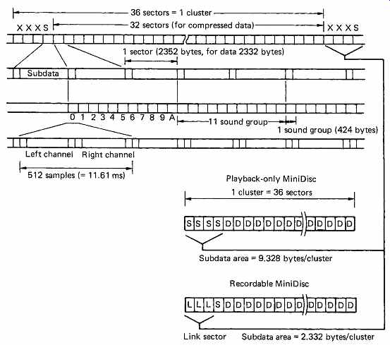
FIG. 50 Format of MD uses clusters of sectors including link sectors
for editing.
Prerecorded MDs do not need link sectors, so more subcode capacity is available. The ATRAC coder of MD produces the sound groups shown here.
17. Track layout of MD
MD uses the same channel code and error-correction interleave as CD for simplicity and the sectors are exactly the same size. The interleave of CD is convolutional, which is not a drawback in a continuous recording.
However, MD uses random access and the recording is discontinuous.
FIG. 49 shows that the convolutional interleave causes codewords to run between sectors. Rerecording a sector would prevent error correction in the area of the edit. The solution is to use a buffering zone in the area of an edit where the convolution can begin and end. This is the job of the link sectors. FIG. 50 shows the layout of data on a recordable MD. In each cluster of 36 sectors, 32 are used for encoded audio data. One is used for subcode and the remaining three are link sectors. The cluster is the minimum data quantum which can be recorded and represents just over two seconds of decoded audio. The cluster must be recorded continuously because of the convolutional interleave. Effectively the link sectors form an edit gap which is large enough to absorb both mechanical tolerances and the interleave overrun when a cluster is rewritten. One or more clusters will be assembled in memory before writing to the disk is attempted.
Prerecorded MDs are recorded at one time, and need no link sectors. In order to keep the format consistent between the two types of MiniDisc, three extra subcode sectors are made available. As a result it is not possible to record the entire audio and subcode of a prerecorded MD onto a recordable MD because the link sectors cannot be used to record data.
The ATRAC coder produces what are known as sound groups (see Section 5). Figure 50 shows that these contain 212 bytes for each of the two audio channels and are the equivalent of 11.6ms of real-time audio.
Eleven of these sound groups will fit into two standard CD sectors with 20 bytes to spare. The 32 audio data sectors in a cluster thus contain a total of 16 x 11 = 176 sound groups.