Outline of Digital Audio in Optical Disks:
CD, DVD and MD contrasted
CD and MD -- disk construction
Rejecting surface contamination
Playing optical disks
Focus systems
Tracking systems
Typical pickups
DVD and CD readout in detail
How optical disks are made
Direct metal mastering
MiniDisc read/write in detail
How recordable MiniDiscs are made
Channel code of CD and MiniDisc
Deserialization
Error-correction strategy
Track layout of MD
CD subcode
MD table of contents
CD player structure
MD recorder/player structure
Structure of a DVD player
References
Optical disks are particularly important to digital audio, not least because of the success of the Compact Disc and subsequent developments such as MiniDisc, magneto-optical production recorders and DVD. CD, DVD and MiniDisc are worthy of detailed consideration, as they are simultaneously consumer products available in large numbers at low cost, and yet are technically advanced devices. Optical disks result from the marriage of many disciplines, including laser optics, servomechanisms, error correction and both analog and digital circuitry in VLSI form.
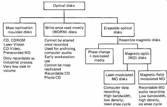
FIG. 1 The various types of optical disk. See text for details.
1. Types of optical disk
There are numerous types of optical disk, which have different characteristics.
There are, however, three broad groups, shown in FIG. 1, which can be usefully compared:
1. The Compact Disc, the Digital Video Disc and the prerecorded MiniDisc are read-only laser disks, which are designed for mass duplication by stamping. They cannot be recorded.
2. Some laser disks can be recorded, but once a recording has been made, it cannot be changed or erased. These are usually referred to as write once-read-mostly (WORM) disks. Recordable CDs and DVDs work on this principle.
3. Erasable optical disks have essentially the same characteristic as magnetic disks, in that new and different recordings can be made in the same track indefinitely. Recordable MiniDisc is in this category.
Sometimes a separate erase process is necessary before rewriting.
The Compact Disc, generally abbreviated to CD, is a consumer digital audio recording which is intended for mass replication. When optical recording was in its infancy, many companies were experimenting with a variety of optical media. In most cases the goal was to make an optical recorder where the same piece of apparatus could record and immediately reproduce information. This would be essential for most computer applications and for use in audio or video production.
This was not, however, the case in the consumer music industry, where the majority of listening was, and still is, to prerecorded music. The vinyl disk could not be recorded in the home, yet it sold by the million. Individual vinyl disks were not recorded as such by the manufacturer as they were replicated by pressing, or molding, molten plastic between two surfaces known as stampers which were them selves made from a master disk produced on a cutting lathe. This master disk was the recording.

FIG. 2 (a) The information layer of CD is reflective and uses interference.
(b) Write-once disks may burn holes or raise blisters in the information layer.
(c) High data rate MO disks modulate the laser and use a constant magnetic
field. (d) At low data rates the laser can run continuously and the magnetic
field is modulated.
Philips' approach was to invent an optical medium which would have the same characteristics as the vinyl disk in that it could be mass replicated by molding or stamping with no requirement for it to be recordable by the user. The information on it is carried in the shape of flat-topped physical deformities in a layer of plastic, and as a result the medium has no photographic, magnetic or electronic properties, but is simply a relief structure. Such relief structures lack contrast and are notoriously difficult to study with conventional optics, but in 1934 Zernike2 described a Nobel Prize-winning technique called phase contrast microscopy which allowed an apparent contrast to be obtained from such a structure using optical interference. This principle is used to read relief recordings.
FIG. 2(a) shows that the information layer of CD and the prerecorded MiniDisc is an optically flat mirror upon which microscopic bumps are raised. A thin coating of aluminum renders the layer reflective. When a small spot of light is focused on the information layer, the presence of the bumps affects the way in which the light is reflected back, and variations in the reflected light are detected in order to read the disk. FIG. 2 also illustrates the very small dimensions which are common to both disks. For comparison, some sixty CD/MD tracks can be accommodated in the groove pitch of a vinyl LP. These dimensions demand the utmost cleanliness in manufacture.
FIG. 2(b) shows that there are several types of WORM disks. The disk may contain a thin layer of metal; on recording, a powerful laser melts spots on the layer. Surface tension causes a hole to form in the metal, with a thickened rim around the hole. Subsequently a low-power laser can read the disk because the metal reflects light, but the hole passes it through. Computer WORM disks work on this principle. As an alternative, the layer of metal may be extremely thin, and the heat from the laser heats the material below it to the point of decomposition. This causes gassing which raises a blister or bubble in the metal layer.
Recordable CDs can use this principle as the relief structure can be read like a normal CD. It is also possible to impregnate a disk with a chemical dye which darkens when it is struck by a high level of radiation from a writing laser. Clearly once such a pattern of holes, blisters or dark areas has been made it is permanent.
Re-recordable or erasable optical disks rely on magneto-optics, 3 also known more fully as thermomagneto-optics. Writing in such a device makes use of a thermomagnetic property possessed by all magnetic materials, which is that above a certain temperature, known as the Curie temperature, their coercive force becomes zero. This means that they become magnetically very soft, and take on the flux direction of any externally applied field. On cooling, this field orientation will be frozen in the material, and the coercivity will oppose attempts to change it.
Although many materials possess this property, there are relatively few which have a suitably low Curie temperature. Compounds of terbium and gadolinium have been used, and one of the major problems to be overcome is that almost all suitable materials from a magnetic viewpoint corrode very quickly in air.
There are two ways in which magneto-optic (MO) disks can be written.
FIG. 2(c) shows the first system, in which the intensity of laser is modulated with the waveform to be recorded. If the disk is considered to be initially magnetized along its axis of rotation with the north pole upwards, it is rotated in a field of the opposite sense, produced by a steady current flowing in a coil which is weaker than the room temperature coercivity of the medium. The field will therefore have no effect. A laser beam is focused on the medium as it turns, and a pulse from the laser will momentarily heat a very small area of the medium past its Curie temperature, whereby it will take on a reversed flux due to the presence of the field coils. This reversed-flux direction will be retained indefinitely as the medium cools.
Alternatively the waveform to be recorded modulates the magnetic field from the coils as shown in FIG. 2(d). In this approach, the laser is operating continuously in order to raise the track beneath the beam above the Curie temperature, but the magnetic field recorded is determined by the current in the coil at the instant the track cools.
Magnetic field modulation is used in the recordable MiniDisc.
In both of these cases, the storage medium is clearly magnetic, but the writing mechanism is the heat produced by light from a laser; hence the term thermomagneto-optics. The advantage of this writing mechanism is that there is no physical contact between the writing head and the medium. The distance can be several millimeters, some of which is taken up with a protective layer to prevent corrosion. In prototypes, this layer is glass, but commercially available disks use plastics.
The laser beam will supply a relatively high power for writing, since it is supplying heat energy. For reading, the laser power is reduced, such that it cannot heat the medium past the Curie temperature, and it is left on continuously. Readout depends on the so-called Kerr effect, which describes a rotation of the plane of polarization of light due to a magnetic field. The magnetic areas written on the disk will rotate the plane of polarization of incident polarized light to two different planes, and it is possible to detect the change in rotation with a suitable pickup.
Erasable disks may also be made which rely on phase changes. Certain chemical compounds may exist in two states, crystalline or amorphous.
One state appears shiny and the other dull to a readout beam. It is possible to switch from one state to another by using different power levels in the laser.
2. CD, DVD and MD contrasted
CD and MD have a great deal in common. Both use a laser of the same wavelength which creates a spot of the same size on the disk. The track pitch and speed are the same and both offer the same playing time. The channel code and error-correction strategy are the same. DVD uses the same principle as CD, but the readout spot is smaller so that the recording density can significantly be raised.
CD carries 44.1 kHz 16-bit PCM audio and is intended to be played in a continuous spiral like a vinyl disk. The CD process, from cutting, through pressing and reading, produces no musical degradation whatsoever, since it simply conveys a series of numbers which are exactly those recorded on the master tape. The only part of a CD player which can cause subjective differences in sound quality in normal operation is the DAC, although in the presence of gross errors some players will correct and/or conceal better than others. Section 4 deals with the principles of conversion.
DVD records an MPEG program stream. This is a multiplex of compressed audio and video elementary streams which can be decoded to reproduce television programs or movies.
MD begins with the same PCM data as CD, but uses a form of compression known as ATRAC (see Section 5) having a compression factor of 0.2 which introduces a slight but audible loss of quality. After the addition of subcode and housekeeping data MD has an average data rate which is 0.225 that of CD. However, MD has the same recording density and track speed as CD, so the data rate from the disk is greatly in excess of that needed by the audio decoders. The difference is absorbed in RAM exactly as shown in Figure 10.34.
The RAM in a typical MD player is capable of buffering about 3 seconds of audio. When the RAM is full, the disk drive stops transferring data but keeps turning. As the RAM empties into the decoders, the disk drive will top it up in bursts. As the drive need not transfer data for over three quarters of the time, it can reposition between transfers and so it is capable of editing in the same way as a magnetic hard disk. A further advantage of a large RAM buffer is that if the pickup of a CD or MD player is knocked off-track by an external shock the RAM continues to provide data to the audio decoders and provided the pickup can get back to the correct track before the RAM is exhausted there will be no audible effect.
When recording an MO disk, the MiniDisc drive also uses the RAM buffer to allow repositioning so that a continuous recording can be made on a disk which has become checker boarded through selective erasing.
The full total playing time is then always available irrespective of how the disk is divided into different recordings.
CD and MD have a fixed bit rate, whereas DVD does not. It is a characteristic of video material that the degree of compression possible varies with program material. Consequently the greatest efficiency is obtained if the bit rate can increase to handle complex pictures and slow down again to handle simple images. In a multiplex a variable video bit rate can exist alongside a fixed audio bit rate.
3. CD and MD - disk construction
FIG. 3 shows the mechanical specification of CD. Within an overall diameter of 120mm the program area occupies a 33mm-wide band between the diameters of 50 and 116mm. Lead-in and lead-out areas increase the width of this band to 35.5mm. As the track pitch is a constant
1.6 m, there will be 35.6 x 1000/1.6 = 22 188
tracks crossing a radius of the disk. As the track is a continuous spiral, the track length will be given by the above figure multiplied by the average circumference:
Length = 2 x pi x [58.5 + 23]/2 x 22 188 = 5.7 km

FIG. 3 Mechanical specification of CD. Between diameters of 46 and 117mm
is a spiral track 5.7 km long.
These figures give a good impression of the precision involved in CD manufacture. The CD case is for protection in storage and the CD has to be taken out of its case and placed in the player. The disk has a plain center hole and most players clamp the disk onto the spindle from both sides. There are some CD players designed for broadcasters which require the standard CD to be placed into a special cassette. The CD can then be played inside the cassette.
FIG. 4 shows the mechanical specification of prerecorded Mini Disc. Within an overall diameter of 64mm the lead-in area begins at a diameter of 29mm and the program area begins at 32mm. The track pitch is exactly the same as in CD, but the MiniDisc can be smaller than CD without any sacrifice of playing time because of the use of compression.
For ease of handling, MiniDisc is permanently enclosed in a shuttered plastic cartridge which is 72 x 68 x 5mm. The cartridge resembles a smaller version of a 3 1/2-inch floppy disk, but unlike a floppy, it is slotted into the drive with the shutter at the side. An arrow is molded into the cartridge body to indicate this.

FIG. 4 The mechanical dimensions of MiniDisc.
In the prerecorded MiniDisc, it was a requirement that the whole of one side of the cartridge should be available for graphics. Thus the disk is designed to be secured to the spindle from one side only. The center of the disk is fitted with a ferrous clamping plate and the spindle is magnetic.
When the disk is lowered into the drive it simply sticks to the spindle.
The ferrous disk is only there to provide the clamping force. The disk is still located by the molded hole in the plastic component. In this way the ferrous component needs no special alignment accuracy when it is fitted in manufacture. The back of the cartridge has a center opening for the hub and a sliding shutter to allow access by the optical pickup.
The recordable MiniDisc and cartridge has the same dimensions as the prerecorded MiniDisc, but access to both sides of the disk is needed for recording. Thus the recordable MiniDisc has a shutter which opens on both sides of the cartridge, rather like a double-sided floppy disk. The opening on the front allows access by the magnetic head needed for MO recording, leaving a smaller label area.
FIG. 5 shows the construction of the MO MiniDisc. The 1.1m wide tracks are separated by grooves which can be optically tracked.
Once again the track pitch is the same as in CD. The MO layer is sandwiched between protective layers.

FIG. 5 The construction of the MO recordable MiniDisc.
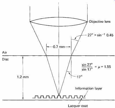
FIG. 6 The objective lens of a CD pickup has a numerical aperture (NA)
of 0.45; thus the outermost rays will be inclined at approximately 27° to the
normal. Refraction at the air/disk interface changes this to approximately
17° within the disk. Thus light focused to a spot on the information layer
has entered the disk through a 0.7mm diameter circle, giving good resistance
to surface contamination.
4. Rejecting surface contamination
A fundamental goal of consumer optical disks is that no special working environment or handling skill is required. The bandwidth needed by PCM audio is such that high-density recording is mandatory if reasonable playing time is to be obtained in CD. Although MiniDisc uses compression, it does so in order to make the disk smaller and the recording density is actually the same as for CD.
High-density recording implies short wavelengths. Using a laser focused on the disk from a distance allows short-wavelength recordings to be played back without physical contact, whereas conventional magnetic recording requires intimate contact and implies a wear mechanism, the need for periodic cleaning, and susceptibility to contamination.
The information layer of CD and MD is read through the thickness of the disk. FIG. 6 shows that this approach causes the readout beam to enter and leave the disk surface through the largest possible area. The actual dimensions involved are shown in the figure. Despite the minute spot size of about 1.2m diameter, light enters and leaves through a 0.7mm-diameter circle. As a result, surface debris has to be three orders of magnitude larger than the readout spot before the beam is obscured.
This approach has the further advantage in MO drives that the magnetic head, on the opposite side to the laser pickup, is then closer to the magnetic layer in the disk.

FIG. 7 Plane-wave propagation considered as infinite numbers of spherical
waves.

FIG. 8 Reflection and refraction, showing the effect of the velocity
of light in a medium.
The bending of light at the disk surface is due to refraction of the wavefronts arriving from the objective lens. Wave theory of light suggests that a wavefront advances because an infinite number of point sources can be considered to emit spherical waves which will only add when they are all in the same phase. This can only occur in the plane of the wavefront. FIG. 7 shows that at all other angles, interference between spherical waves is destructive.
When such a wavefront arrives at an interface with a denser medium, such as the surface of an optical disk, the velocity of propagation is reduced; therefore the wavelength in the medium becomes shorter, causing the wavefront to leave the interface at a different angle (FIG. 8). This is known as refraction. The ratio of velocity in vacuum to velocity in the medium is known as the refractive index of that medium; it determines the relationship between the angles of the incident and refracted wavefronts. Reflected light, however, leaves at the same angle to the normal as the incident light. If the speed of light in the medium varies with wavelength, dispersion takes place, where incident white light will be split into a rainbow-like spectrum leaving the interface at different angles. Glass used for chandeliers and cut glass is chosen to be highly dispersive, whereas glass for optical instruments will be chosen to have a refractive index which is as constant as possible with changing wavelength. The use of monochromatic light in optical disks allows low cost optics to be used as they only need to be corrected for a single wavelength.
The size of the entry circle in FIG. 6 is a function of the refractive index of the disk material, the numerical aperture of the objective lens and the thickness of the disk. MiniDiscs are permanently enclosed in a cartridge, and scratching is unlikely. This is not so for CD, but fortunately the method of readout through the disk thickness tolerates surface scratches very well. In extreme cases of damage, a scratch can often successfully be removed with metal polish. By way of contrast, the label side is actually more vulnerable than the readout side, since the lacquer coating is only 30m thick. For this reason, writing on the label side of CD is not recommended. Pressure from a ballpoint pen could distort the information layer, and solvents from marker pens have been known to penetrate the lacquer and cause corruption. The common party-piece of writing on the readout surface of CD with a felt pen to show off the error correction system is quite harmless, since the disk base material is impervious to most solvents.
The base material is in fact a polycarbonate plastic produced by (among others) Bayer under the trade name of Makrolon. It has excellent mechanical and optical stability over a wide temperature range, and lends itself to precision molding and metallization. It is often used for automotive indicator clusters for the same reasons. An alternative material is polymethyl methacrylate (PMMA), one of the first optical plastics, known by such trade names as Perspex and Plexiglas, and widely used for illuminated signs and aircraft canopies. Polycarbonate is preferred by some manufacturers since it is less hygroscopic than PMMA. The differential change in dimensions of the lacquer coat and the base material can cause warping in a hygroscopic material. Audio disks are too small for this to be a problem, but the larger analog video disks are actually two disks glued together back-to-back to prevent this warpage.
5. Playing optical disks
A typical laser disk drive resembles a magnetic drive in that it has a spindle drive mechanism to revolve the disk, and a positioner to give radial access across the disk surface. The positioner has to carry a collection of lasers, lenses, prisms, gratings and so on, and cannot be accelerated as fast as a magnetic-drive positioner. A penalty of the very small track pitch possible in laser disks, which gives the enormous storage capacity, is that very accurate track following is needed, and it takes some time to lock onto a track. For this reason tracks on laser disks are usually made as a continuous spiral, rather than the concentric rings of magnetic disks. In this way, a continuous data transfer involves no more than track following once the beginning of the file is located.
In order to record MO disks or replay any optical disk, a source of monochromatic light is required. The light source must have low noise otherwise the variations in intensity due to the noise of the source will mask the variations due to reading the disk. The requirement for a low noise monochromatic light source is economically met using a semi conductor laser.
The semiconductor laser is a relative of the light-emitting diode (LED).
Both operate by raising the energy of electrons to move them from one valence band to another conduction band. Electrons which fall back to the valence band emit a quantum of energy as a photon whose frequency is proportional to the energy difference between the bands. The process is described by Planck's Law:
Energy difference E = H x f where H = Planck's Constant
= 6.6262 x 10^-34 joules/Hertz For gallium arsenide, the energy difference is about 1.6 eV, where 1 eV is 1.6 x 10^-19 joules.
Using Planck's Law, the frequency of emission will be:
f = 1.6 x 1.6 x 10^-19/6.6262x 10^-34 Hz
The wavelength will be c/f where
c = the velocity of light = 3 x 10^8 m/s
Wavelength = 3 x 10^8 x 6.6262 x 10^-34/2.56 x 10^-19 m = 780 nanometers
In the LED, electrons fall back to the valence band randomly, and the light produced is incoherent. In the laser, the ends of the semiconductor are optically flat mirrors, which produce an optically resonant cavity. One photon can bounce to and fro, exciting others in synchronism, to produce coherent light. This is known as light amplification by stimulated emission of radiation, mercifully abbreviated to LASER, and can result in a runaway condition, where all available energy is used up in one flash.
In injection lasers, an equilibrium is reached between energy input and light output, allowing continuous operation. The equilibrium is delicate, and such devices are usually fed from a current source. To avoid runaway when temperature change disturbs the equilibrium, a photosensor is often fed back to the current source. Such lasers have a finite life, and become steadily less efficient. The feedback will maintain output, and it is possible to anticipate the failure of the laser by monitoring the drive voltage needed to give the correct output.
Some of the light reflected back from the disk re-enters the aperture of objective lens. The pickup must be capable of separating the reflected light from the incident light. FIG. 9 shows two systems. In (a) an intensity beamsplitter consisting of a semisilvered mirror is inserted in the optical path and reflects some of the returning light into the photosensor. This is not very efficient, as half of the replay signal is lost by transmission straight on. In the example at (b) separation is by polarization.

FIG. 9 (a) Reflected light from the disk is directed to the sensor by
a semisilvered mirror. (b) A combination of polarizing prism and quarter-wave
plate separates incident and reflected light.

FIG. 10 (a) Linear polarization: orthogonal components are in phase.
(b) Circular polarization: orthogonal components are in phase quadrature.

FIG. 11 Different speed of light in different planes rotates the plane
of polarization in a quarter-wave plate to give a circular-polarized output.
In natural light, the electric-field component will be in many planes.
Light is said to be polarized when the electric field direction is constrained. The wave can be considered as made up from two orthogonal components. When these are in phase, the polarization is said to be linear. When there is a phase shift between the components, the polarization is said to be elliptical, with a special case at 90° called circular polarization. These types of polarization are contrasted in FIG. 10.
In order to create polarized light, anisotropic materials are necessary.
Polaroid material, invented by Edwin Land, is vinyl which is made anisotropic by stretching it while hot. This causes the long polymer molecules to line up along the axis of stretching. If the material is soaked in iodine, the molecules are rendered conductive, and short out any electric-field component along themselves. Electric fields at right angles are unaffected; thus the transmission plane is at right angles to the stretching axis.
Stretching plastics can also result in anisotropy of refractive index; this effect is known as birefringence. If a linearly polarized wavefront enters such a medium, the two orthogonal components propagate at different velocities, causing a relative phase difference proportional to the distance travelled. The plane of polarization of the light is rotated.
Where the thickness of the material is such that a 90° phase change is caused, the device is known as a quarter-wave plate. The action of such a device is shown in FIG. 11. If the plane of polarization of the incident light is at 45° to the planes of greatest and least refractive index, the two orthogonal components of the light will be of equal magnitude, and this results in circular polarization. Similarly, circular polarized light can be returned to the linear-polarized state by a further quarter-wave plate. Rotation of the plane of polarization is a useful method of separating incident and reflected light in a laser pickup. Using a quarter-wave plate, the plane of polarization of light leaving the pickup will have been turned 45°, and on return it will be rotated a further 45°, so that it is now at right angles to the plane of polarization of light from the source. The two can easily be separated by a polarizing prism, which acts as a transparent block to light in one plane, but as a prism to light in the other plane, such that reflected light is directed towards the sensor.

FIG. 12 A pickup suitable for the replay of magneto-optic disks must
respond to very small rotations of the plane of polarization.
In a CD player, the sensor is concerned only with the intensity of the light falling on it. When playing MO disks, the intensity does not change, but the magnetic recording on the disk rotates the plane of polarization one way or the other depending on the direction of the vertical magnetization. MO disks cannot be read with circular-polarized light.
Light incident on the medium must be plane polarized and so the quarter-wave plate of the CD pickup cannot be used. FIG. 12(a) shows that a polarizing prism is still required to linearly polarize the light from the laser on its way to the disk. Light returning from the disk has had its plane of polarization rotated by approximately ± 1°. This is an extremely small rotation. Figure 12.12(b) shows that the returning rotated light can be considered to be composed of two orthogonal components.
Rx is the component which is in the same plane as the illumination and is called the ordinary component and Ry is the component due to the Kerr effect rotation and is known as the magneto-optic component. A polarizing beam splitter mounted squarely would reflect the magneto-optic component Ry very well because it is at right angles to the transmission plane of the prism, but the ordinary component would pass straight on in the direction of the laser. By rotating the prism slightly a small amount of the ordinary component is also reflected. Figure 12(c) shows that when combined with the magneto-optic component, the angle of rotation has increased. [4] Detecting this rotation requires a further polarizing prism or analyzer as shown in FIG. 12. The prism is twisted such that the transmission plane is at 45° to the planes of Rx and Ry . Thus with an unmagnetized disk, half of the light is transmitted by the prism and half is reflected. If the magnetic field of the disk turns the plane of polarization towards the transmission plane of the prism, more light is transmitted and less is reflected. Conversely if the plane of polarization is rotated away from the transmission plane, less light is transmitted and more is reflected. If two sensors are used, one for transmitted light and one for reflected light, the difference between the two sensor outputs will be a waveform representing the angle of polarization and thus the recording on the disk. This differential analyzer eliminates common-mode noise in the reflected beam. [5] As FIG. 12 shows, the output of the two sensors is summed as well as subtracted in a MiniDisc player. When playing MO disks, the difference signal is used. When playing prerecorded disks, the sum signal is used and the effect of the second polarizing prism is disabled.
Since the residual stresses set up in molding plastic tend to align the long-chain polymer molecules, plastics can have different refractive indices in different directions, a phenomenon known as birefringence. It is possible accidentally to rotate the plane of polarization of light in bi-refringent plastics, and there were initial reservations as to the feasibility of this approach for playing molded CDs. The necessary quality of disk molding was achieved by using relatively high temperatures where the material flows more easily. This has meant that birefringence is negligible, and the polarizing beamsplitter is widely used.
6. Focus systems
The frequency response of the laser pickup and the amount of crosstalk are both a function of the spot size and care must be taken to keep the beam focused on the information layer. If the spot on the disk becomes too large, it will be unable to discern the smaller features of the track, and can also be affected by the adjacent track. Disk warp and thickness irregularities will cause focal-plane movement beyond the depth of focus of the optical system, and a focus servo system will be needed. The depth of field is related to the numerical aperture, which is defined, and the accuracy of the servo must be sufficient to keep the focal plane within that depth, which is typically ± 1 m.
The focus servo moves a lens along the optical axis in order to keep the spot in focus. Since dynamic focus-changes are largely due to warps, the focus system must have a frequency response in excess of the rotational speed. A moving-coil actuator is often used owing to the small moving mass which this permits. Figure 13 shows that a cylindrical magnet assembly almost identical to that of a loudspeaker can be used, coaxial with the light beam. Alternatively a moving-magnet design can be used.
A rare earth magnet allows a sufficiently strong magnetic field without excessive weight.

FIG. 13 Moving-coil-focus servo can be coaxial with the light beam as
shown.
A focus-error system is necessary to drive the lens. There are a number of ways in which this can be derived, the most common of which will be described here.

FIG. 14 The cylindrical lens focus method produces an elliptical spot
on the sensor whose aspect ratio is detected by a four-quadrant sensor to produce
a focus error.

FIG. 15 (a)-(c) Knife-edge focus method requires only two sensors, but
is critically dependent on knife-edge position. (d)-(f) Twin-prism method requires
three sensors (A, B, C), where focus error is (A + C) - B. Prism alignment
reduces sensitivity without causing focus offset.
In FIG. 14 a cylindrical lens is installed between the beamsplitter and the photosensor. The effect of this lens is that the beam has no focal point on the sensor. In one plane, the cylindrical lens appears parallel sided, and has negligible effect on the focal length of the main system, whereas in the other plane, the lens shortens the focal length. The image will be an ellipse whose aspect ratio changes as a function of the state of focus. Between the two foci, the image will be circular. The aspect ratio of the ellipse, and hence the focus error, can be found by dividing the sensor into quadrants. When these are connected as shown, the focus-error signal is generated. The data readout signal is the sum of the quadrant outputs.
FIG. 15 shows the knife-edge method of determining focus. A split sensor is also required. At (a) the focal point is coincident with the knife edge, so it has little effect on the beam. At (b) the focal point is to the right of the knife edge, and rising rays are interrupted, reducing the output of the upper sensor. At (c) the focal point is to the left of the knife edge, and descending rays are interrupted, reducing the output of the lower sensor.
The focus error is derived by comparing the outputs of the two halves of the sensor. A drawback of the knife-edge system is that the lateral position of the knife edge is critical, and adjustment is necessary. To overcome this problem, the knife edge can be replaced by a pair of prisms, as shown in FIG. 15(d)-(f). Mechanical tolerances then only affect the sensitivity, without causing a focus offset.
The cylindrical lens method is compared with the knife-edge/prism method in FIG. 16, which shows that the cylindrical lens method has a much smaller capture range. A focus-search mechanism will be required, which moves the focus servo over its entire travel, looking for a zero crossing. At this time the feedback loop will be completed, and the sensor will remain on the linear part of its characteristic. The spiral track of CD and MiniDisc starts at the inside and works outwards. This was deliberately arranged because there is less vertical run-out near the hub, and initial focusing will be easier.
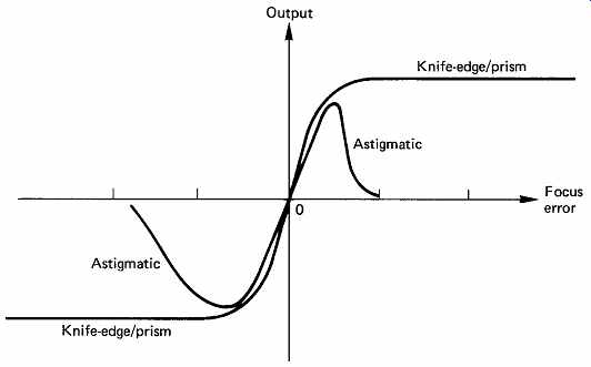
FIG. 16 Comparison of captive range of knife-edge/prism method and astigmatic
(cylindrical lens) system. Knife edge may have a range of 1mm, whereas astigmatic
may only have a range of 40m, requiring a focus-search mechanism.
7. Tracking systems
The track pitch is only 1.6 m, and this is much smaller than the accuracy to which the player chuck or the disk center hole can be made; on a typical player, run-out will swing several tracks past a fixed pickup. The non-contact readout means that there is no inherent mechanical guidance of the pickup. In addition, a warped disk will not present its surface at 90° to the beam, but will constantly change the angle of incidence during two whole cycles per revolution. Owing to the change of refractive index at the disk surface, the tilt will change the apparent position of the track to the pickup, and Figure 17 shows that this makes it appear wavy. Warp also results in coma of the readout spot. The disk format specifies a maximum warp amplitude to keep these effects under control. Finally, vibrations induced in the player from outside, particularly in portable and automotive players, will tend to disturb tracking. A track-following servo is necessary to keep the spot centralized on the track in the presence of these difficulties. There are several ways in which a tracking error can be derived.

FIG. 17 Owing to refraction, the angle of incidence (i) is greater than
the angle of refraction (r). Disk warp causes the apparent position of the
track (dashed line) to move, requiring the tracking servo to correct.
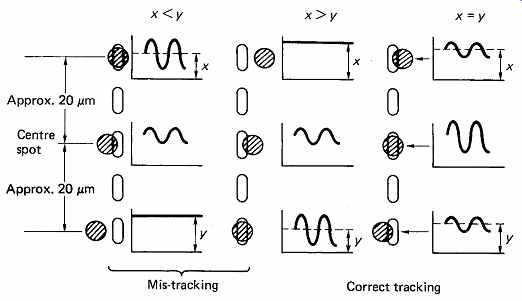
FIG. 18 Three-spot method of producing tracking error compares average
level of side-spot signals. Side spots are produced by a diffraction grating
and require their own sensors.

FIG. 19 Diffraction as a plane wave reaches a small aperture.
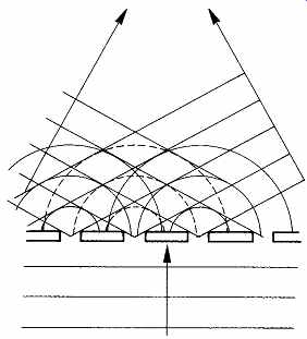
FIG. 20 In a diffraction grating, constructive interference can take
place at more than one angle for a single wavelength.
In the three-spot method, two additional light beams are focused on the disk track, one offset to each side of the track centerline. FIG. 18 shows that, as one side spot moves away from the track into the mirror area, there is less destructive interference and more reflection. This causes the average amplitude of the side spots to change differentially with tracking error. The laser head contains a diffraction grating which produces the side spots, and two extra photosensors onto which the reflections of the side spots will fall. The side spots feed a differential amplifier, which has a low-pass filter to reject the channel-code information and retain the average brightness difference. Some players use a delay line in one of the side-spot signals whose period is equal to the time taken for the disk to travel between the side spots. This helps the differential amplifier to cancel the channel code.
The side spots are generated as follows. When a wavefront reaches an aperture which is small compared to the wavelength, the aperture acts as a point source, and the process of diffraction can be observed as a spherical wavefront leaving the aperture as in FIG. 19. Where the wavefront passes through a regular structure, known as a diffraction grating, light on the far side will form new wavefronts wherever radiation is in phase, and FIG. 20 shows that these will be at an angle to the normal depending on the spacing of the structure and the wavelength of the light. A diffraction grating illuminated by white light will produce a dispersed spectrum at each side of the normal. To obtain a fixed angle of diffraction, monochromatic light is necessary.
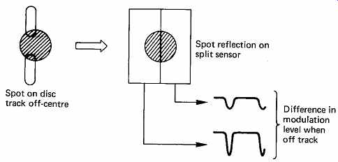
FIG. 21 Split-sensor method of producing tracking error focuses image
of spot onto sensor. One side of spot will have more modulation when off-track.
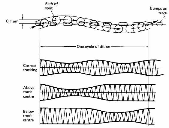
FIG. 22 Dither applied to readout spot modulates the readout envelope.
A tracking error can be derived.
The alternative approach to tracking-error detection is to analyze the diffraction pattern of the reflected beam. The effect of an off-center spot is to rotate the radial diffraction pattern about an axis along the track.
FIG. 21 shows that, if a split sensor is used, one half will see greater modulation than the other when off-track. Such a system may be prone to develop an offset due either to drift or to contamination of the optics, although the capture range is large. A further tracking mechanism is often added to obviate the need for periodic adjustment. FIG. 22 shows this dither-based system, which resembles in many respects the track following method used in many professional videotape recorders. A sinusoidal drive is fed to the tracking servo, causing a radial oscillation of spot position of about ± 50 nm. This results in modulation of the envelope of the readout signal, which can be synchronously detected to obtain the sense of the error. The dither can be produced by vibrating a mirror in the light path, which enables a high frequency to be used, or by oscillating the whole pickup at a lower frequency.
8. Typical pickups
It is interesting to compare different designs of laser pickup. FIG. 23 shows a Philips laser head. 6 The dual-prism focus method is used, which combines the output of two split sensors to produce a focus error. The focus amplifier drives the objective lens which is mounted on a parallel motion formed by two flexural arms. The capture range of the focus system is sufficient to accommodate normal tolerances without assistance. A radial differential tracking signal is extracted from the sensors as shown in the figure. Additionally, a dither frequency of 600Hz produces envelope modulation which is synchronously rectified to produce a drift free tracking error. Both errors are combined to drive the tracking system.
As only a single spot is used, the pickup is relatively insensitive to angular errors, and a rotary positioner can be used, driven by a moving coil. The assembly is statically balanced to give good resistance to lateral shock.
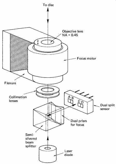
FIG. 23 Philips laser head showing semisilvered prism for beam splitting.
Focus error is derived from dual-prism method using split sensors. Focus error
(A + D) - (B + C) is used to drive focus motor which moves objective lens on
parallel action flexure.
Radial differential tracking error is derived from split sensor (A + B) - (C + D). Tracking error drives entire pickup on radial arm driven by moving coil. Signal output is (A + B + C + D). System includes 600Hz dither for tracking. (Courtesy Philips Technical Review)

FIG. 24 Sony laser head showing polarizing prism and quarter-wave plate
for beam splitting, and diffraction grating for production of side spots for
tracking. The cylindrical lens system is used for focus, with a four-quadrant
sensor (A, B, C, D) and two extra sensors E, F for the side spots. Tracking
error is E-F; focus error is (A + C) - (B + D). Signal output is (A + B + C
+ D). The focus and tracking errors drive the two-axis device. (Courtesy Sony
Broadcast)

FIG. 25 For automotive and portable players, the pickup can be made more
compact by incorporating a mirror, which allows most of the elements to be
parallel to the disk instead of at right angles.
FIG. 24 shows a Sony laser head used in consumer players. The cylindrical-lens focus method is used, requiring a four-quadrant sensor.
Since this method has a small capture range, a focus-search mechanism is necessary. When a disk is loaded, the objective lens is ramped up and down looking for a zero crossing in the focus error. The three-spot method is used for tracking. The necessary diffraction grating can be seen adjacent to the laser diode. Tracking error is derived from side-spot sensors (E, F). Since the side-spot system is sensitive to angular error, a parallel-tracking laser head traversing a disk radius is essential. A cost effective linear motion is obtained by using a rack-and-pinion drive for slow, coarse movements, and a laterally moving lens in the light path for fine rapid movements. The same lens will be moved up and down for focus by the so-called two-axis device, which is a dual-moving coil mechanism. In some players this device is not statically balanced, making the unit sensitive to shock, but this was overcome on later heads designed for portable players. FIG. 25 shows a later Sony design having a prism which reduces the height of the pickup above the disk.