8. Timecode in DAT
The subcode of DAT is recorded in areas outside the ATF patterns, physically distinct from the PCM area. As a result, the subcode can be independently edited after an audio recording has been made. The DAT subcode performs the functions of program access in much the same way as in the Compact Disc, but it also has a subset of codes for professional use which allows the recording of timecode for synchronizing and edit control purposes.
The PCM audio data are primarily intended to be played at normal speed, with a reduced quality at other speeds. In contrast, the subcode must function well over a wide speed range so that it can be used for high-speed searching to cues. For this reason the structure of the subcode is repetitive to increase the chance of pickup, but it has no outer redundancy, as outer codes could not be assembled in shuttle.
FIG. 22 shows the general arrangement of the subcode sync blocks.
Like the PCM sync blocks, the subcode blocks have eight bytes of C1 redundancy in every other block, so there is a two-block sequence. The subcode data are assembled into standard-sized messages known as packs which contain eight bytes. In the first block of the pair, up to four packs can be accommodated, whereas in the second, only three are present because of the presence of the C1 redundancy.

FIG. 22 Subcode blocks are used in pairs, owing to the inner code
interleave. The first block contains up to four packs, whereas the second
block contains only three packs and 8 bytes of C1 (inner) redundancy.
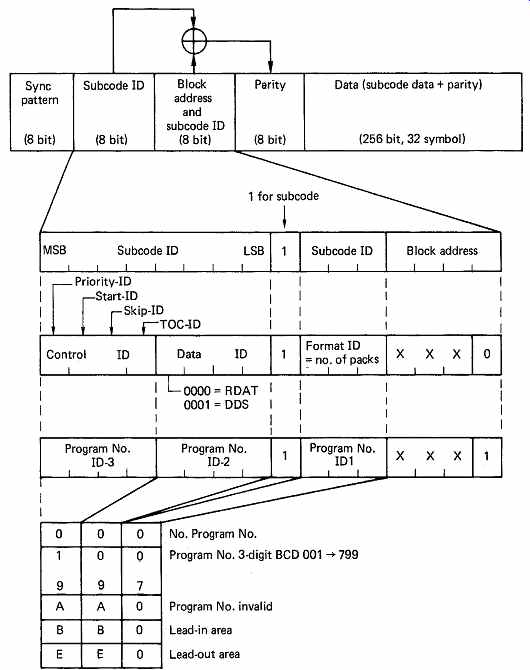
FIG. 23 The headers in an adjacent pair of subcode sync blocks are
interpreted as shown here.
The header structure of the subcode is identical to that of the PCM data.
FIG. 23 shows that following the sync byte there are two header bytes, followed by a parity byte generated on the first two. The MSB of the block address byte is always 1 in the subcode, to distinguish subcode from PCM data. There are eight subcode blocks at each end of the track, so the four LSBs of the block address byte convey the block number 0-15. The LSB of the block number allows the player to determine whether the first or second block of the subcode sequence has been found.
The smaller range of block addresses leaves three bits in the second header byte for other purposes. In the first block of the pair, these three bits form the Format ID which specifies the number of packs which have been recorded in the pair of blocks.
The first byte of the header in an even-numbered block is split into the Control ID and the Data ID. The Control ID consists of four individual flags. TOC-ID is set if the block contains Table of Contents packs. Skip-ID causes the machine to fast forward to the next Start-ID, which serves a similar function to the P-flag in Compact Disc. Finally, Priority-ID is set if the Program Number (P-No.) in the odd-numbered subcode header has been edited, so that the subcode P-No. has priority over any P-No. in the PCM-ID which cannot be edited independently of the audio. Data-ID serves the same purpose as ID-0 in PCM-ID; all zeros indicate subcode should be interpreted as digital audio standard, 1000 indicates DDS format (Digital Data Storage) subcode.
The majority of subcode data are stored in eight-byte packs in the subdata area. FIG. 24(a) shows the basic layout of a pack. The four MSBs of the first Pack Contents (PC) symbol contain the Item code which defines the meaning of the rest of the pack. The last PC is a simple XOR parity symbol calculated by adding PC 1 through PC 7 in modulo-2.
FIG. 24(b) shows the current valid Item codes. Program Time, Absolute Time and Running Time all have the same basic pack layout which is shown in FIG. 25. As stated, the first four bits of PC 1 are the Item code. Bit 3 of PC 1 must be zero, leaving three bits in PC 1 and the whole of PC 2 to form an eleven-bit Program Number (P-No.). In this context the word 'Program' corresponds to a band on a vinyl LP; it is one song or movement. PC 3 contains the index code which optionally allows a Program to be subdivided. The remaining symbols PC 4-7 carry the time information in hours, minutes, seconds and DAT scanner frames (33.33 . . .Hz).
When DAT is to be used for professional applications, timecode recording is often essential. DAT timecode is carried in a pack known as Professional Running Time, abbreviated to Pro R time.
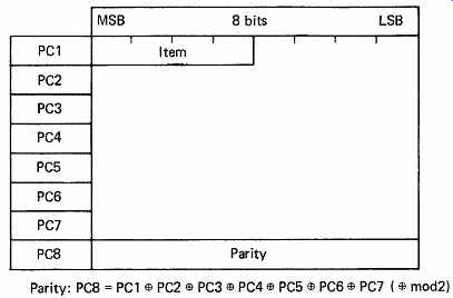
FIG. 24 (a) General structure of a pack.
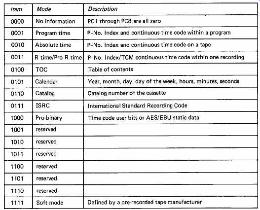
FIG. 24 (b) Table of item codes which identify the type of pack which
has been recovered. Item 0011 carries running time in consumer format and
Pro R time in professional timecode version.
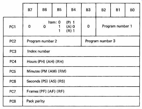
FIG. 25 Program, absolute and running time all share the same pack
structure, but with different item codes. For example, with the item code
0001, PC4 contains program hours (PH). With item code 0011, PC7 contains
running time frames (RF).
There are many forms of timecode arising from the variety of frame rates used in television and film. As DAT is in international use, the adoption of a single timecode standard to the exclusion of others is not acceptable. The solution is to record a universal form of timecode on the tape, and to use conversion circuitry appropriate to the frame rate of the system with which it is proposed to work. Internally DAT Pro R time records hours, minutes, seconds and DAT frames (33.33 . . .Hz) which relate simply to the scanner speed. The relationship of DAT frames to frames in one of the standard timecodes produces a variety of phase relationships as shown in FIG. 26.
FIG. 26(a) shows the example of EBU 25Hz television timecode being fed into a DAT recorder. The phase relationship between the frame boundaries changes from frame to frame. The phase relationship measured in samples is known as the Timecode Marker. It is recorded in the Pro R time pack along with the DAT frame number. The pack is also recorded with the sampling rate in use and the type of timecode being input. On replay, there is sufficient information in the pack to allow a suitable processor to compute from the DAT timecode and marker the position and content of EBU timecode frames which will have the same relationship to the audio samples as they originally had. The timecode marker consists of a binary number which can vary from zero up to the number of sample periods in a DAT frame (959, 1322 or 1439 according to the sampling rate in use). FIG. 26(b) shows the situation with 24Hz film timecode.
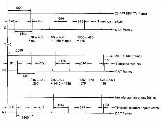
FIG. 26 At (a) the timecode marker (TCM) can be predicted from the
previous TCM in a synchronous system, as shown here for sample-rate-locked
25Hz timecode. At (b) the TCM can also be predicted if the sampling rate
is synchronous to 24Hz film. At (c) if the source frame rate is not synchronous
or unstable, TCMs cannot be predicted but must be individually measured.
When a DAT recorder contains a built-in timecode generator, it will be simple to synchronize it to the sampling rate, and this is the preferred mode of operation. In this case the next timecode marker can be calculated by subtracting a constant from the previous one and expressing the result modulo the number of sample periods in a DAT frame.
Synchronous timecode and sampling rate are essential if a tape is to be played into a digital system via a timecode synchronizer. The system cannot lock to two things at once, so if a tape has asynchronous timecode and sampling rate, the synchronizer will make the replay sampling rate drift, or the sampling-rate reference will make the timecode drift.
However, if the replay is to be done in the analog domain, the sampling rate drift is of no consequence, and asynchronous working is acceptable.
The DAT timecode system still works without synchronism between the external timecode signal and the scanner speed. The only difference is that the Timecode Marker parameter cannot be predicted, but will have to be measured at each scanner rotation. FIG. 26(c) shows an example of asynchronous working.
Pro R time is recorded using a modification of the R time pack (Item 0011) as shown in FIG. 24. Normally bit 3 of PC 1 in this pack is set to zero; for Pro R time it is set to 1 and the interpretation of the pack changes.
Bits F0 and F1 in PC 2 reflect the audio sampling rate. The Sub-Pack bits SPI-0 and SPI-1 determine whether the timecode recorded is one of the film/television timecodes, or whether it is the embedded timecode of the AES/EBU digital audio interface. When these bits are both zero, the pack is in film/television mode, and bits T0, T1 and T2 specify the frame rate in use. The remaining three bits of PC 2 and the whole of PC 3 form the eleven-bit Timecode Marker.
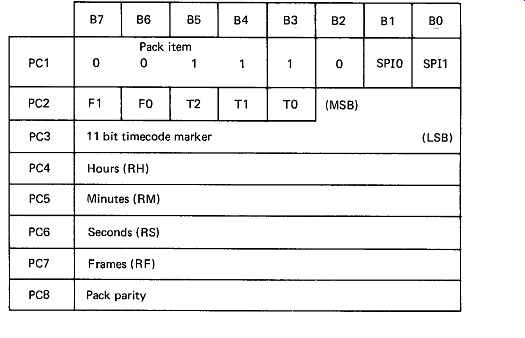
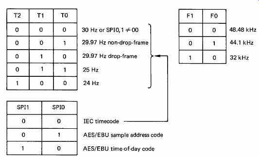
FIG. 27 Contents of Pro R time pack. An eleven-bit TCM can be seen
in PC2-3, when SP10, 1 are 00, T0-2 specify the timecode rate in use when
the recording was made. As TCM is in sample periods, F0, F1 are necessary
to decode correctly at the sampling rate used.
DAT timecode is measured in the usual hours, minutes, seconds and frames, with the prefix R. RH, RM, RS and RF are all two-digit BCD numbers. Since there are not a whole number of DAT frames in a second, two of the seconds contain 33 frames and the third contains 34 frames.
This results in exactly 100 frames in 3 seconds. As in all packs, PC 8 is the modulo-2 sum of all of the other PCs.
The sample address form of timecode conveyed in the AES/EBU digital audio interface (see Section 8) can be carried in the pack with the Sub-Pack bits set to 01. The AES/EBU channel-status data frame repeats every 192 sample periods (4ms at 48 kHz) and contains (among other data) a 32-bit code which is a binary count of the number of sample clocks since midnight at the beginning of the frame. Since there will be several AES/EBU frames in one DAT frame, the DAT pack records the sample address of the AES/EBU frame during which a DAT frame began, converted to DAT timecode, and the Timecode Marker parameter is the number of sample periods from the beginning of the AES/EBU frame to the beginning of the DAT frame. The principle is shown in FIG. 27.
Conversion from the various forms of input timecode into DAT timecode is based on the fact that all forms of timecode begin from midnight with all parameters at zero. Knowledge of the basic frame rate of the standard concerned allows any actual timecode values to be converted to real time. This can then be converted back to DAT timecode. As a result, the timecode recorded by DAT is truly inter national. A recording made with EBU 25Hz timecode as an input results in DAT timecode on the tape. This could, with a suitable player, generate SMPTE timecode when the tape is played. The timecode conversion equations are given in Super-section 1.
9. Non-tracking replay
For replay only, it is possible to dispense with the scanner and ATF servos in some applications. The scanner free-runs at approximately twice normal speed, whilst the capstan continues to run at the correct speed.
The rotary heads cross tracks randomly, but because of the increased speed, virtually every sync block is recovered, many of them twice. The increased scanner speed requires a higher clock frequency in the data separator.
Each pair of sync blocks contains two inner codewords, and those which are found to be error-free or which contain correctable random errors can be used. Each sync block contains an ID pattern and this is used to put the data in the correct place in the product block. If a second copy of any sync block is recovered it is discarded at this stage.
Once the product code memory is full, the de-interleave and error correction process can occur as normal. Any blocks which are not recovered due to track crossing will be treated as dropouts by the error correction system, as will genuine dropouts.
In personal portable machines and car-dashboard players the above approach allows a cost saving since two servo systems are eliminated. A further advantage is that alignment of the scanner is not necessary during manufacture, and tapes which are recorded on misaligned machines can still be played. Mistracking resulting from shock and vibration has no effect since the system is mistracking all the time.
The Sony NT (Non-Tracking) Format uses this approach. The rotary head format uses a postage stamp-sized cassette and has no scanner servo in replay. The non-tracking approach means that interchange alignment is unnecessary. The slant guides on each side of the scanner are actually molded into the cassette reducing mechanical complexity and cost. A 32 kHz sampling rate and data reduction allow a realistic playing time despite the minute cassette.
10. Quarter-inch rotary
Following work which suggests that a rotary-head machine can accept spliced tape, Kudelski 7 proposed a format for 1/4-inch tape using a rotary head which became that of the NAGRA D. This machine offers four independently recordable channels of up to 20-bit wordlength and timecode facilities. The block structure is basically that of the audio channels of the D-1 DVTR. The format is restricted to low-density recording because of the potential for contamination with open reels.
Whilst the recording density is not as great as in DAT, it is still competitive with professional analog machines and as the NAGRA D is a professional only product, tape consumption is of less consequence than reliability. Manual splicing of a helical scan tape causes a serious tracking and data loss problem at the splice. The principle of jump editing (see Section 11) is used so that the area of the splice is not played.
11. Half-inch and 8mm rotary formats
A number of manufacturers have developed low-cost digital multitrack recorders for the home studio market. These are based on either VHS or Video-8 rotary-head cassette tape decks and generally offer eight channels of audio. Recording of individual audio channels is possible because the slant tape tracks are divided up into separate blocks for each channel with edit gaps between them. Some models have timecode and include synchronizers so that several machines can be locked together to offer more tracks. These machines represent the future of multitrack recording as their purchase and running costs are considerably lower than that of stationary head machines. It is only a matter of time before a low-cost 24-track is offered.
12. Digital audio in VTRs
The audio samples in a DVTR are binary numbers just like the video samples, and although there is an obvious difference in sampling rate and wordlength, this only affects the relative areas of tape devoted to the audio and video samples. The most important difference between audio and video samples is the tolerance to errors. The acuity of the ear means that uncorrected audio samples must not occur more than once every few hours. There is little redundancy in sound, and concealment of errors is not desirable on a routine basis. In video, the samples are highly redundant, and concealment can be effected using samples from previous or subsequent lines or, with care, from the previous frame. Major differences can be expected between the ways that audio and video samples are handled in a DVTR. One such difference is that the audio samples have 100 per cent redundancy: every one is recorded using about twice as much space on tape as the same amount of video data.
In DVTR formats the audio samples are carried by the same channel as the video samples. Using separate heads would have increased tape consumption and machine complexity. The use of the same rotary heads for video and audio reduces the number of preamplifiers and data separators needed in the system, whilst increasing the bandwidth requirement by only a few per cent even with double recording. In order to permit independent audio and video editing, the tape tracks are given a block structure. Editing will require the heads momentarily to go into record as the appropriate audio block is reached. Accurate synchronization is necessary if the other parts of the recording are to remain uncorrupted.
The concept of a head which momentarily records in the center of a track which it is reading is the normal operating procedure for all computer disk drives, as will be seen in Section 10. There are in fact many parallels between digital helical recorders and disk drives. Perhaps the only major difference is that in one the heads move slowly and the medium revolves, whereas in the other, the medium moves slowly and the heads revolve.
Disk drives support their heads on an air bearing, achieving indefinite head life at the expense of linear density. Helical digital machines must use high-density recording and so there will be head contact and a wear mechanism. With these exceptions, the principles of disk recording apply to DVTRs, and some of the terminology has migrated.
One of these terms is the sector. In moving-head disk drives, the sector address is a measure of the angle through which the disk has rotated. This translates to the phase of the scanner in a rotary-head machine. The part of a track which is in one sector is called a block. The word 'sector' is often used instead of 'block' in casual parlance when it is clear that only one head is involved. However, as DVTRs have two heads in action at any one time, the word 'sector' means the two side-by-side blocks in the segment. As there are four independently recordable audio channels, there are four audio sectors. In D-1 (FIG. 28), the audio is in the center of the track, so there must be two video sectors and four audio sectors in one head sweep, and since there are two active heads, in one sweep there will be four video blocks written and eight audio blocks. In D-2 and D-3 there are also two active heads in each sweep, but the audio blocks are at the ends of the tracks, so that there are only two video blocks in the center.
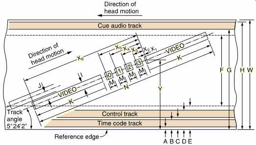
FIG. 28 The track arrangements of D-1. Note that the segment begins
at X1 after the audio blocks. The arrangement of the D-1 control track
is such that servo pulses coincide with the beginning of an even segment
after the audio blocks. The next segment has no control track pulse, and
so the pulses repeat at drum rotation rate for a four-headed machine. Additional
pulses locate the top segment in a frame and record optional color framing.
There is a requirement for the DVTR to produce pictures in shuttle. In this case, the heads cross tracks randomly, and it is most unlikely that complete video blocks can be recovered. To provide pictures in shuttle, each block is broken down into smaller components called sync blocks in the same way as is done in DAT. These contain their own error checking and an address, which in disk terminology would be called a header, which specifies where in the picture the samples in the sync block belong.
In shuttle, if a sync block is read properly, the address can be used to update a frame store. Thus it can be said that a sector is the smallest amount of data which can be written and is that part of a track pair within the same sector address, whereas a sync block is the smallest amount of data which can be read. Clearly there are many sync blocks in a sector.
The sync block structure continues in the audio because the same read/ write circuitry is almost always used for audio and video data. Clearly the address structure must also continue through the audio. In order to prevent audio samples from arriving in the video frame store in shuttle, the audio addresses are different from the video addresses. In all formats, the arrangement of the audio blocks is designed to maximize data integrity in the presence of tape defects and head clogs. The allocation of the audio channels to the sectors is often changed from one segment to the next. If a linear tape scratch damages the data in a given audio channel in one segment, it will damage a different audio channel in the next. Thus the scratch damage is shared between all four audio channels, each of which need correct only one quarter of the damage. It will also be seen that the relationship of the audio channels to the physical tracks rotates by one track against the direction of tape movement from one audio sector to the next. The effect of this is that, if a head becomes clogged, the errors will be distributed through all audio channels, instead of causing severe damage in one channel. In the D-2 format the audio blocks are at the ends of the head sweeps; the audio information is split so that half is recorded at each edge of the tape, and each half will be played with a different head.
In each sector, the track commences with a preamble to synchronize the phase-locked loop in the data separator on replay. Each of the sync blocks begins, as the name suggests, with a synchronizing pattern which allows the read sequencer to deserialize the block correctly. At the end of a sector, it is not possible simply to turn off the write current after the last bit, as the turnoff transient would cause data corruption. It is necessary to provide a postamble such that current can be turned off away from the data. It should now be evident that any editing has to take place a sector at a time. Any attempt to rewrite one sync block would result in damage to the previous block owing to the physical inaccuracy of replacement, damage to the next block due to the turnoff transient, and inability to synchronize to the replaced block because of the random phase jump at the point where it began. The sector in a DVTR is analogous to the cluster in a disk drive. Owing to the difficulty of writing in exactly the same place as a previous recording, it is necessary to leave tolerance gaps between sectors where the write current can turn on and off to edit individual write blocks. For convenience, the tolerance gaps are made the same length as a whole number of sync blocks. The first half of the tolerance gap is the postamble of the previous block, and the second half of the tolerance gap acts as the preamble for the next block. The tolerance gap following editing will contain, somewhere in the center, an arbitrary jump in bit phase, and a certain amount of corruption due to turnoff transients. Provided that the postamble and preamble remain intact, this is of no consequence.
The number of audio sync blocks in a given time is determined by the number of video fields in that time. It is only possible to have a fixed tape structure if the audio sampling rate is locked to video. With 625/50 machines, the sampling rate of 48 kHz results in exactly 960 audio samples in every field.
For use on 525/60, it must be recalled that the 60Hz is actually 59.94Hz.
As this is slightly slow, it will be found that in sixty fields, exactly 48 048 audio samples will be necessary. Unfortunately 60 will not divide into 48 048 without a remainder. The largest number which will divide 60 and 48 048 is 12; thus in 60/12 = 5 fields there will be 48 048/12 = 4004 samples.
Over a five-field sequence the product blocks contain 801, 801, 801, 801 and 800 samples respectively, adding up to 4004 samples.
In order to comply with the AES/EBU digital audio interconnect, wordlengths between sixteen and twenty bits can be supported, but it is necessary to record a code in the sync block to specify the wordlength in use. Pre-emphasis may have been used prior to conversion, and this status is also to be conveyed, along with the four channel-use bits. The AES/EBU digital interconnect (see Section 8) uses a block-sync pattern which repeats after 192 sample periods corresponding to 4ms at 48 kHz.
He who confuses block sync with sync block is lost. Since the block size is different from that of the DVTR interleave block, there can be any phase relationship between interleave-block boundaries and the AES/EBU block-sync pattern. In order to re-create the same phase relationship between block sync and sample data on replay, it is necessary to record the position of block sync within the interleave block. It is the function of the interface control word in the audio data to convey these parameters.
There is no guarantee that the 192-sample block-sync sequence will remain intact after audio editing; most likely there will be an arbitrary jump in block-sync, phase. Strictly speaking, a DVTR playing back an edited tape would have to ignore the block-sync positions on the tape, and create new block sync at the standard 192-sample spacing. Unfortunately the DVTR formats are not totally transparent to the whole of the AES/EBU data stream, as certain information is not recorded.
13. Stationary-head recorders
Stationary-head digital audio recorders have fixed heads like an analog recorder and often resemble their analog ancestors closely. Stationary head multi-track recorders were developed in preference to rotary head because of the perceived need to support splicing and because the electronic circuitry required was simpler. Stationary head recording is not as efficient as rotary and in the long term the familiar digital multi-track will give way to rotary cassette-based formats with electronic editing. The stereo stationary head PCM recorder has already succumbed to DAT and hard disks in professional use. The use of compression allows the efficiency problem to be overcome for consumer products and this resulted in the digital compact cassette (DCC).
Professional stationary-head recorders were specifically designed for record production and mastering, and had to be able to offer all the features of an analog multitrack. Digital multitracks mimicked analog machines so exactly that they could be installed in otherwise analog studios with the minimum of fuss. When the stationary head formats were first developed, the necessary functions of a professional machine were: independent control of which tracks record and play, synchronous recording, punch-in/punch-out editing, tape-cut editing, variable-speed playback, offtape monitoring in record, various tape speeds and bandwidths, autolocation and the facilities to synchronize several machines.
In both theory and practice a rotary-head recorder can achieve a higher storage density than a stationary-head recorder, thus using less tape.
When multitrack digital audio recorders were first proposed, the adaptation of an analog video-recorder transport had to be ruled out because it lacked the necessary bandwidth. For example, a 24-track machine requires about 20 megabits per second. A further difficulty is that helical-scan recorders were not designed to handle tape-cut edits which were then considered necessary. Accordingly, multitrack digital audio recorders evolved with stationary heads and open reels; they look like analog recorders, but offer sufficient bandwidth and support splicing.
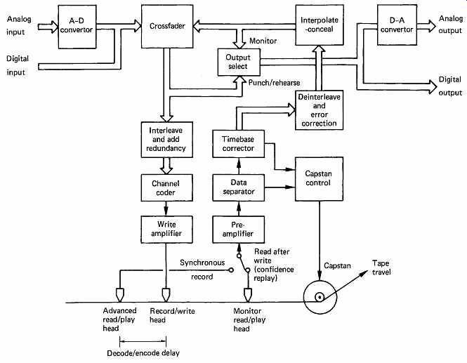
FIG. 29 Block diagram of typical open-reel digital audio recorder.
Note advanced head for synchronous recording, and capstan controlled by
replay circuits.
A stationary-head digital recorder is basically quite simple, as the block diagram of FIG. 29 shows. The transport is not dissimilar to that of an analog recorder. The tape substrate used in professional analog recording is quite thick to reduce print-through, whereas in digital recording, the tape is very thin, rather like videotape, to allow it to conform closely to the heads for short-wavelength working. Print-through is not an issue in digital recording. The roughness of the backcoat has to be restricted in digital tape to prevent it embossing the magnetic layer of the adjacent turn when on the reel, since this would nullify the efforts made to provide a smooth surface finish for good head contact. The roughness of the backcoat allows the boundary layer to bleed away between turns when the tape is spooled, and so digital recorders do not spool as quickly as analog recorders. They cannot afford to risk the edge damage which results from storing a poor tape pack. The digital transport has rather better tension and reel-speed control than an analog machine. Some transports offer a slow-wind mode to achieve an excellent pack on a tape prior to storage.
Control of the capstan is rather different too, being more like that of a video recorder. The capstan turns at constant speed when a virgin tape is being recorded, but for replay, it will be controlled to run at whatever speed is necessary to make the offtape sample rate equal to the reference rate. In this way, several machines can be kept in exact synchronism by feeding them with a common reference. Variable-speed replay can be achieved by changing the reference frequency. It should be emphasized that, when variable speed is used, the output sampling rate changes. This may not be of any consequence if the samples are returned to the analog domain, but it prevents direct connection to a digital mixer, since these usually have fixed sampling rates.
The major items in the block diagram have been discussed in the relevant sections. Samples are interleaved, redundancy is added, and the bits are converted into a suitable channel code. In stationary-head recorders, the frequencies in each head are low, and complex coding is not difficult. The lack of the rotary transformer of the rotary-head machine means that DC content is less of a problem. The codes used generally try to emphasize density ratio, which keeps down the linear tape speed, and the jitter window, since this helps to reject the inevitable crosstalk between the closely spaced heads. DC content in the code is handled using adaptive slicers as detailed in Section 6. On replay there are the usual data separators, timebase correctors and error-correction circuits.
14. DASH format The DASH8
format was the most successful of the stationary-head formats.
It was not one format as such, but a family of like formats, supporting a number of different track layouts. With ferrite-head technology, it was possible to obtain adequate channel SNR with 24 tracks on half-inch tape (H) and eight tracks on quarter-inch tape (Q). The reason that these numbers are not pro-rata is that the same number of analog and control tracks are necessary for both, and take up proportionately more space on the narrower tape. This gave rise to the single-density family of formats known as DASH I. The most successful member of this family was the Sony PCM-3324.
The dimensions of the 24-track tape layout are shown in FIG. 30. The analog tracks are placed at the edges where they act as guard bands for the digital tracks, protecting them from edge lifting. Additionally there is a large separation between the analog tracks and the digital tracks. This prevents the bias from the analog heads from having an excessive erasing effect on the adjacent digital tracks. For the same reason AC erase may have to be ruled out. One alternative mechanism for erasure of the analog tracks is to use two DC heads in tandem. The first erases the tape by saturating it, and the second is wound in the opposite sense, and carries less current, to return the tape to a near-demagnetized state.
In the half-inch format, the timecode and control tracks are placed at the center of the tape, where they suffer no more skew with respect to the digital tracks than those at the edge of quarter-inch tape in the presence of tape weave.
The construction of a bulk ferrite multitrack head is shown in FIG. 31, where it will be seen that space must be left between the magnetic circuits to accommodate the windings. Track spacing is improved by putting the windings on alternate sides of the gap. The parallel close spaced magnetic circuits have considerable mutual inductance, and suffer from crosstalk. This can be compensated when several adjacent tracks record together by cross-connecting antiphase feeds to the record amplifiers.
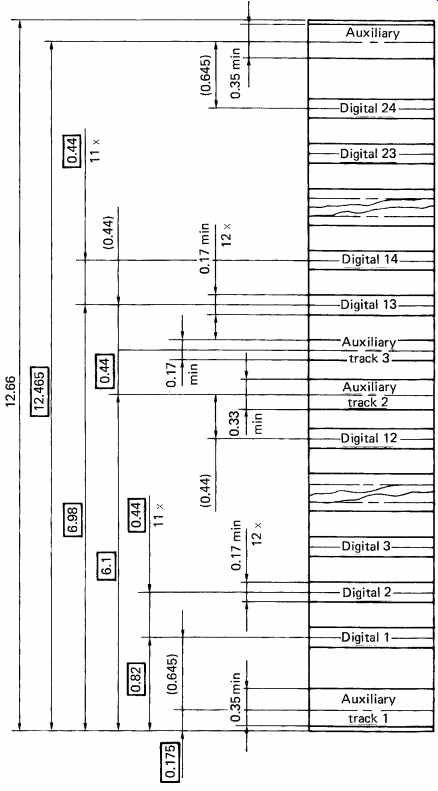
FIG. 30 The track dimensions for DASH IH (half-inch) tape.
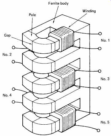
FIG. 31 A typical ferrite head used for DASH I. Windings are placed
on alternate sides to save space, but parallel magnetic circuits have high
crosstalk.
Using thin-film heads, the magnetic circuits and windings are produced by deposition on a substrate at right angles to the tape plane, and as seen in FIG. 32 they can be made very accurately at small track spacings.
Perhaps more importantly, because the magnetic circuits do not have such large parallel areas, mutual inductance and crosstalk are smaller, allowing a higher practical track density.
The so-called double-density version, known as DASH II, uses such thin-film heads to obtain 48 digital tracks on half-inch tape and sixteen tracks on quarter-inch tape. The 48-track version of DASH II is shown in FIG. 33 where it will be seen that the dimensions allow 24 of the replay head gaps on a DASH II machine to align with and play tapes recorded on a DASH I machine. In fact the PCM-3348 could take 24-track tapes and record a further 24 tracks on them.
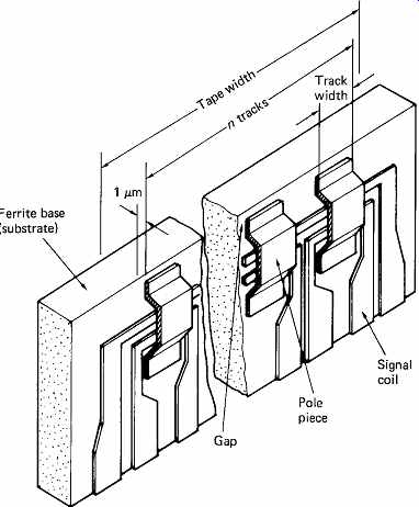
FIG. 32 The thin-film head shown here can be produced photographically
with very small dimensions. Flat structure reduces crosstalk. This type
of head is suitable for DASH II which has twice as many tracks as DASH
I.
The DASH format supported three sampling rates and the tape speed is normalized to 30 in./s at the highest rate. The three rates are 32 kHz, 44.1 kHz and 48 kHz. This last frequency was originally 50.4 kHz, which had a simple fractional relationship to 44.1 kHz, but this was dropped in favor of 48 kHz when arbitrary sampling rate conversion was shown to be feasible. In fact most stationary-head recorders will record at any reasonable sampling rate just by supplying them with an external crosstalk, reference, or word clock, at the appropriate frequency. Under these conditions, the sampling-rate switch on the machine only controls the status bits in the recording which set the default playback rate.
In the digital domain it is quite easy to distribute samples from one audio channel over a number of tape tracks. In DASH-F, the fast version, one audio track requires one tape track, and the tape moves at its greatest speed. In DASH-M, the medium version, one audio channel is spread over two tape tracks, and the tape runs at half speed. In DASH-S, the slow version, one audio channel is spread over four tape tracks, and the tape runs at one quarter speed. In twin DASH, the data corresponding to one audio channel are recorded twice, giving advantages in splice tolerance.
Clearly the number of audio channels must be halved in twin DASH-F, but in DASH-M and DASH-S, the tape speed could be doubled instead.
By way of example, the well-known PCM-3324 is a DASH-FIH machine:
F = Fast format, one channel per track
I = Single density
H = Half-inch tape, hence 24 tape tracks and 24 audio channels
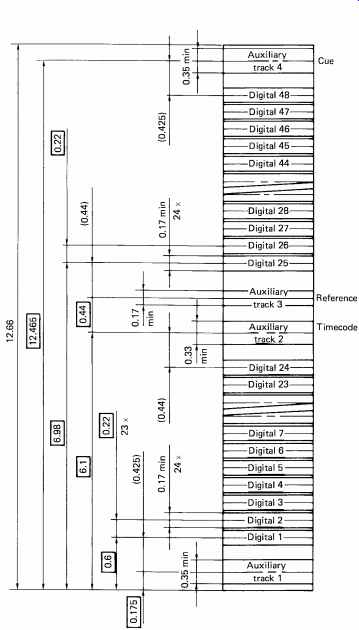
FIG. 33 The track dimensions for DASH IIH (half inch). Comparison
with FIG. 30 will show that half of the tracks align with the single-density
format allowing backwards compatibility.
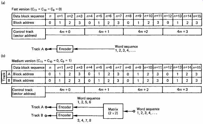
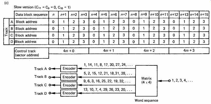
FIG. 34 Relationships of blocks to control-track sectors. In (a),
there are four blocks in one track, representing one audio channel (fast
version). In (b), there are eight blocks in two tracks, representing one
audio channel. The tape speed can be halved to give the medium version.
In (c) there are 16 blocks in four tracks representing one audio channel.
In this, the slow version, speed can be 0.25 of fast version.
The track-allocation mechanisms for S, M and F are shown in FIG. 34 which also depicts the relationship with the control track.
The error-correction strategy of DASH is to form codewords which are confined to single-tape tracks. DASH uses cross-interleaving, which was described in principle in Section 7. In all practical recorders measures have to be taken for the rare cases when the error correction is overwhelmed by gross corruption. In open-reel stationary-head recorders, one obvious mechanism is the act of splicing the tape and the resultant contamination due to fingerprints.
The use of interleaving is essential to handle burst errors; unfortunately it conflicts with the requirements of tape-cut editing. FIG. 35 shows that a splice in cross-interleave destroys codewords for the entire constraint length of the interleave. The longer the constraint length, the greater the resistance to burst errors, but the more damage is done by a splice.
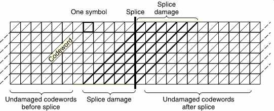
FIG. 35 Although interleave is a powerful weapon against burst errors,
it causes greater data loss when tape is spliced because many codewords
are replayed in two unrelated halves.
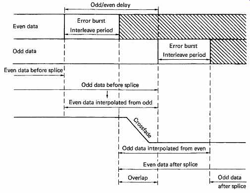
FIG. 36 Following de-interleave, the effect of a splice is to cause
odd and even data to be lost at different times. Interpolation is used
to provide the missing samples, and a crossfade is made when both recordings
are available in the central overlap.
In order to handle dropouts or splices, samples from the convertor or direct digital input are first sorted into odd and even. The odd/even distance has to be greater than the cross-interleave constraint length. In DASH, the constraint length is 119 blocks, or 1428 samples, and the odd/ even delay is 204 blocks, or 2448 samples. In the case of a severe dropout, after the replay de-interleave process, the effect will be to cause two separate error bursts, first in the odd samples, then in the even samples.
The odd samples can be interpolated from the even and vice versa in order to conceal the dropout. In the case of a splice, samples are destroyed for the constraint length, but FIG. 36 shows that this occurs at different times for the odd and even samples. Using interpolation, it is possible simultaneously to obtain the end of the old recording and the beginning of the new one. A digital crossfade is made between the old and new recordings.
The interpolation during concealment and splices causes a momentary reduction in frequency response which may result in aliasing if there is significant audio energy above one quarter of the sampling rate. This was overcome in twin DASH machines in the following way. All incoming samples will be recorded twice, which means twice as many tape tracks or twice the linear speed is necessary. The interleave structure of one of the tracks will be identical to the interleave already described, whereas on the second version of the recording, the odd/even sample shuffle is reversed. When a gross error occurs in twin DASH, it will be seen from FIG. 37 that the result after de-interleave is that when odd samples are destroyed in one channel, even samples are destroyed in the other. By selecting valid data from both channels, a full bandwidth signal can be obtained and no interpolation is necessary. In the presence of a splice, when odd samples are destroyed in one track, even samples will be destroyed in the other track. Thus at all times, all samples will be available without interpolation, and full bandwidth can be maintained across splices. FIG. 38 shows the results of a splice in twin DASH. The status bits in the control track of twin DASH reflect the use of twin recording.
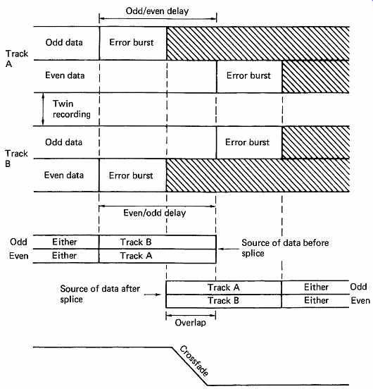
FIG. 37 In twin DASH, the reversed interleave on the twin recordings
means that correct data are always available. This makes twin DASH much
more resistant to mishandling.
15. DCC -- digital compact cassette
DCC is a stationary-head format in which the tape transport is designed to play existing analog Compact Cassettes in addition to making and playing digital recordings. This backward compatibility means that an existing Compact Cassette collection can still be enjoyed whilst newly made or purchased recordings will be digital. [9] To achieve this compatibility, DCC tape is the same width as analog Compact Cassette tape (3.81mm) and travels at the same speed (1 7/8 in./s or 4.76 cm/s). The formulation of the DCC tape is different; it resembles conventional chrome video tape, but the principle of playing one 'side' of the tape in one direction and then playing the other side in the opposite direction is retained.
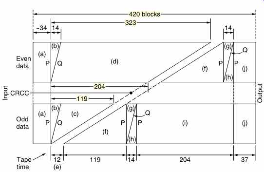
FIG. 38 In twin DASH, two recordings are made of the same data, but
with a reversed interleave. In the area of a splice, when one recording
loses odd samples, the other will lose even samples, and vice versa. By
selecting samples as above, full bandwidth is maintained through the splice,
since no interpolation is necessary.
Although the DCC cassette has similar dimensions to the Compact Cassette so that both can be loaded in the same transport, the DCC cassette is of radically different construction. The DCC cassette only fits in the machine one way, it cannot be physically turned over as it only has hub drive apertures on one side. The head access bulge has gone and the cassette has a uniform rectangular cross-section, taking up less space in storage. The transparent windows have also been deleted as the amount of tape remaining is displayed on the panel of the player. This approach has the advantage that labeling artwork can cover almost the entire top surface. The same approach has been used in pre-recorded MiniDiscs (see Section 12). As the cassette cannot be turned over, all transports must be capable of playing in both directions. Thus DCC is an auto-reverse format. In addition to a record lockout plug, the cassette body carries identification holes. Combinations of these specify six different playing times from 45min to 120min as in Table 1.
The apertures for hub drive, capstans, pinch rollers and heads are covered by a sliding cover formed from metal plate. The cover plate is automatically slid aside when the cassette enters the transport. The cover plate also operates hub brakes when it closes and so the cassette can be left out of its container. The container fits the cassette like a sleeve and has space for an information booklet.
DCC uses a form of data reduction which Philips call Precision Adaptive Sub-band Coding (PASC). PASC is based on MPEG audio compression as described in Section 5 and its use allows the recorded data rate to be about one quarter that of the original PCM audio. This allows for conventional chromium tape to be used with a minimum wavelength of about one micrometer instead of the more expensive high coercivity tapes normally required for use with shorter wavelengths. The advantage of the conventional approach with linear tracks is that tape duplication can be carried out at high speed. This makes DCC attractive to record companies. Even with data reduction, the only way in which the bit rate can be accommodated is to use many tracks in parallel.
FIG. 39 shows that in DCC audio data are distributed over eight parallel tracks along with a subcode track which together occupy half the width of the tape. At the end of the tape the head rotates about an axis perpendicular to the tape and plays the remaining tracks in reverse. The other half of the head is fitted with magnetic circuits sized for analog tracks and so the head rotation can also select the head type which is in use for a given tape direction.
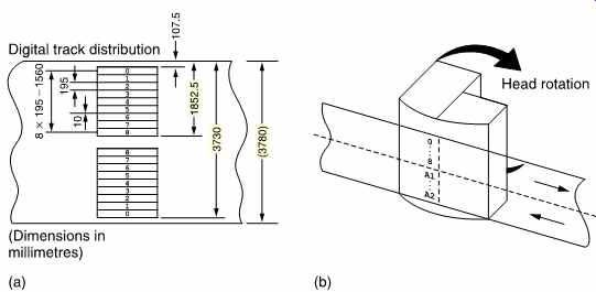
FIG. 39 In DCC audio and auxiliary data are recorded on nine parallel
tracks along each side of the tape as shown in (a). The replay head shown
in (b) carries magnetic poles which register with one set of nine tracks.
At the end of the tape, the replay head rotates 180° and plays a further
nine tracks on the other side of the tape. The replay head also contains
a pair of analog audio magnetic circuits which will be swung into place
if an analog cassette is to be played.
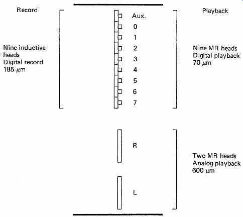
FIG. 40 The head arrangement used in DCC. There are nine record heads
which leave tracks wider than the MR replay heads to allow for misregistration.
Two MR analog heads allow compact cassette replay.
However, reducing the data rate to one quarter and then distributing it over eight tracks means that the frequency recorded on each track is only 96 kbits/s or about 1/16 that of a PCM machine recording a single audio channel with a single head. The linear tape speed is incredibly low by stationary-head digital standards in order to obtain the desired playing time. The rate of change of flux in the replay head is very small due to the low tape speed, and conventional inductive heads are at a severe disadvantage because their self-noise drowns the signal. Magneto resistive heads are necessary because they do not have a derivative action, and so the signal is independent of speed. A magnetoresistive head uses an element whose resistance is influenced by the strength of flux from the tape and its operation was discussed in Section 6. Magneto resistive heads are unable to record, and so separate record heads are necessary. FIG. 40 shows a schematic outline of a DCC head. There are nine inductive record heads for the digital tracks, and these are recorded with a width of 185 m and a pitch of 195m. Alongside the record head are nine MR replay gaps. These operate on a 70 m band of the tape which is nominally in the center of the recorded track. There are two reasons for this large disparity between the record and replay track widths. First, replay signal quality is unaffected by a lateral alignment error of ±57 m and this ensures tracking compatibility between machines. Second, the loss due to incorrect azimuth is proportional to track width and the narrower replay track is thus less sensitive to the state of azimuth adjustment. In addition to the digital replay gaps, a further two analog MR head gaps are present in the replay stack. These are aligned with the two tracks of a stereo pair in a Compact Cassette.
The twenty-gap head could not be made economically by conventional techniques. Instead it is made lithographically using thin film technology.
Tape guidance is achieved by a combination of guides on the head block and pins in the cassette. FIG. 41 shows that at each side of the head is fitted a C-shaped tape guide. This guide is slightly narrower than the nominal tape width. The reference edge of the runs against a surface which is at right angles to the guide, whereas the non-reference edge runs against a sloping surface. Tape tension tends to force the tape towards the reference edge. As there is such a guide at both sides of the head, the tape cannot wander in the azimuth plane. The tape wrap around the head stack and around the azimuth guides is achieved by a pair of pins behind the tape which are part of the cassette. Between the pins is a conventional sprung pressure pad and screen.
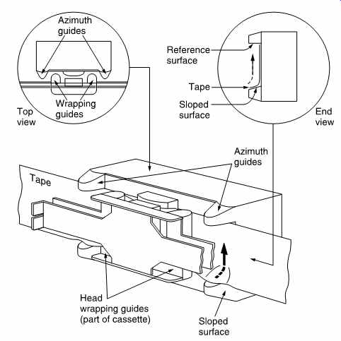
FIG. 41 The tape guidance of DCC uses a pair of shaped guides on both
sides of the head. See text for details.
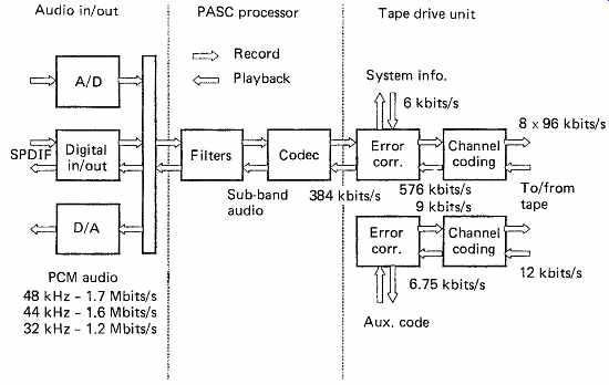
FIG. 42 Block diagram of DCC machine. This is basically similar to
any stationary-head recorder except for the compression (PASC) unit between
the convertors and the transport.
FIG. 42 shows a block diagram of a DCC machine. The audio interface contains convertors which allow use in analog systems. The digital interface may be used as an alternative. DCC supports 48, 44.1 and 32 kHz sampling rates, offering audio bandwidths of 22, 20 and 14.5 kHz respectively with eighteen-bit dynamic range. Between the interface and the tape subsystem is the PASC coder. The tape subsystem requires error-correction and channel coding systems not only for the audio data but also for the auxiliary data on the ninth track.
Super-section 1: Timecode to Pro R time conversion
As explained in the text, conversion from one timecode standard to Pro R time consists of finding the number of the last timecode frame completed before the beginning of the current Pro R time frame. The beginning of both frames is then expressed in real time, and the timecode marker (TCM) measures the difference between them, in sample periods Ts .
The upper part of Fig. A.1 shows EBU timecode frames of period TC beginning from time zero. The number of complete timecode frames before the DAT frame in question begins is the Timecode Frame Count, FC, which is an integer.
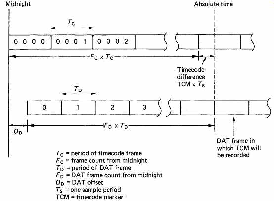
Fig. A.1 Computation of the timecode marker. At top, 25Hz EBU frames
begin from midnight, but DAT frames (below) are not necessarily aligned
with midnight, and the DAT offset OD takes this into account. The absolute
time of the beginning of the DAT frame in question is expressed modulo-TC
which gives the timecode difference. The timecode marker is the timecode
difference measured in sample periods TS.
The lower section of the diagram shows DAT frames of period TD, which did not necessarily begin at time zero. The DAT Offset DO, which is a constant, measures the relationship between the beginning of the first DAT frame and time zero.
The DAT Frame Count FD is the number of completed DAT frames before the one in question. The time difference between the beginnings of the respective frames is TCM x Ts .
The absolute time at the beginning of a given DAT frame is:
FD x TD + OD
The timecode difference TCM x TS is simply the absolute time expressed Modulo-TC. Thus:
TCM = (FD x TD + OD) ModTC / Ts
References
1. Yamada, Y., Fujii, Y., Moriyama, M. and Saitoh, S., Professional use PCM audio processor with a high efficiency error-correction system. Presented at the 66th Audio Engineering Society Convention, (Los Angeles, 1980), Preprint 1628(G7)
2. Ishida, Y., Nishi, S., Kunii, S., Satoh, T. and Uetake, K., A PCM digital audio processor for home use VTRs. Presented at the 64th Audio Engineering Society Convention (New York, 1979), Preprint 1528
3. Griffiths, F.A., A digital audio recording system. Presented at the 65th Audio Engineering Society Convention ( London, 1980), Preprint 1580(C1)
4. Nakajima, H. and Odaka, K., A rotary-head high-density digital audio tape recorder. IEEE Trans. Consum. Electron., CE-29, 430-437 (1983)
5. Itoh, F., Shiba, H., Hayama, M. and Satoh, T., Magnetic tape and cartridge of R-DAT. IEEE Trans. Consum. Electron., CE-32, 442-452 (1986)
6. Hitomi, A. and Taki, T., Servo technology of R-DAT. IEEE Trans. Consum. Electron., CE-32, 425-432 (1986)
7. Kudelski, S., et al., Digital audio recording format offering extensive editing capabilities. Presented at the 82nd Audio Engineering Society Convention ( London, 1987), Preprint 2481(H-7)
8. Doi, T.T., Tsuchiya, Y., Tanaka, M. and Watanabe, N., A format of stationary-head digital audio recorder covering wide range of applications. Presented at the 67th Audio Engineering Society Convention, (New York, 1980), Preprint 1677(H6)
9. Lokhoff, G.C.P., DCC: Digital compact cassette. IEEE Trans. Consum. Electron., CE-37, 702-706 (1991)