In this Section, a brief discussion of the television transmission and broadcast practices will be given. This discussion should not be considered as a complete coverage of the subject since that would fill an entire book of this size. Only those points considered necessary for a general understanding of the basic TV transmission system will be given. A block diagram of the basic TV transmission system will be given. A block diagram of the basic TV transmission system is shown in Fig. 2-1.
TELEVISION-BROADCASTING PRACTICES
The televising of live talent programs presents to the video broadcaster many of the same problems that have confronted the motion-picture industry. Rather elaborate backgrounds are frequently necessary, and they require the same attention to technical detail and period authenticity that is evident in well-staged plays and high-grade motion pictures.
However, unlike motion-picture production, which can be interrupted at will, a live television broadcast must be continuous. The problems of sets, lighting, and equipment require much planning and rehearsal prior to the actual broadcast. Indoor and outdoor televising usually require several cameras strategically located so that the scene can be viewed from various vantage points without sequential interruption.
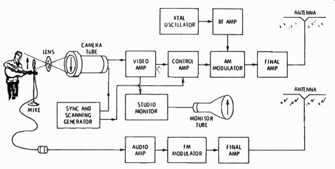
Fig. 2-1. Block diagram of a television transmission system.
In addition to the telecasting of live program material, extensive use is made of motion-picture film in television programming. For this purpose, special projectors are employed, which, by a shutter arrangement, convert the 24-frames/sec film projections into 30-frames/sec television signals. The film picture is projected directly into a television camera, from which the electrical signal is conveyed to the control room over coaxial cable.
Sound pickup from the film is conveyed in the normal manner to the control room over twisted-pair audio cable. Other films are often used for news and commercials. The sound may be provided by a live announcer or may be prerecorded.
Slides are also used for many programs. They offer flexibility in their display order on a program-to-program basis. News, sports, and still commercial broadcasts are common examples.
The projection of slides directly into the television camera has led to the development of the film chain, or film island. This "multiplexing" device employs prisms and mirrors to select which movie projector or slide projector is to be seen by the television camera, reducing the total number of television cameras required.
Videotape recorders are now the accepted medium for most programming. They offer the advantage of being able to record the program at any convenient time for playback at the desired time. Both the picture and sound are included on the magnetic tape, and it is ready for instant playback. No time is lost in processing. Video tapes can be exchanged between stations or distributed by syndicates the same as film. They can also be used for commercials or any other type of presentation.
Network broadcasts, of course, are one of the most common methods of program origination and do not require any program facilities at the local studio. In this type of presentation, the pro gram originates at one point, either live, on film, or on videotape.
This program is then sent out via coaxial-cable microwave relay or satellite to the network stations, where it is transmitted to the viewing public. Sometimes, due to time differentials, the net work program will be recorded on videotape when it is received at the station and played back at a later hour. A typical videotape recorder is shown in Fig. 2-2.
Remote broadcasts offer still other difficulties. Since the connection by coaxial cable from a remote location to the studio is an economic impossibility, small UHF or microwave relay links are employed to connect the remote site with the studio. The relay equipment is usually contained within a special truck that houses, not only the relay transmitter, but also complete control and monitoring facilities. Of course, if the event is not to be viewed until a later hour, the program can be videotaped at the remote location. The tape facilities can be taken from the remote point and transported back to the studio, or the relay link can be utilized and the recording made at the studio.
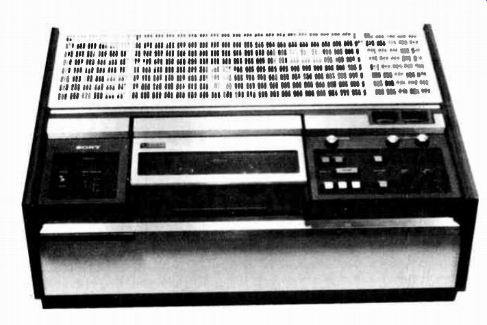
Fig. 2-2 Typical videotape recorder.
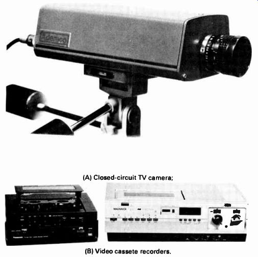
Fig. 2-3. (A) Closed-circuit TV camera; (B) video cassette recorders.
(A) Closed-circuit TV camera, (B) Video-cassette recorders.
CLOSED-CIRCUIT TELEVISION
Closed-circuit television originally designated a local system consisting of a TV camera and several monitors connected by coaxial cables. Today, closed-circuit TV refers also to elaborate private installations, which are widely used by industry, commerce, and education. Microwave transmission is used in some of the larger closed-circuit TV systems. The basic distinction is in the fact that only private groups are served by a closed-circuit system. Scanning standards are usually the same as used in public TV broadcasting, although slow-scan standards, for example, may be used to transmit signature records in banks.
Equipment used in closed-circuit TV is similar to conventional broadcast TV equipment, except that the units may be less elaborate. For example, the TV camera shown in Fig. 2-3 employs a vidicon tube. A video output is provided, which is usually fed to TV monitors via coaxial cables. Videotape recorders, such as the one shown in Fig. 2-3, find wide use in educational installations.
They provides a video-frequency signal, which is fed via a coaxial cable to the TV monitors and applied directly to the video amplifier in each monitor. The TV camera may be used when "live" classroom activities are to be transmitted by the closed circuit system.
Since a typical closed-circuit TV camera produces a video signal with a bandwidth up to 10 MHz, the chief limitation on picture detail and quality is imposed by the TV monitors used in the viewing locations. If the video-signal output is applied directly to the video amplifier in a monitor, the quality of picture reproduction may exceed that of a standard TV broadcast program.
Practically all closed-circuit cameras are transistorized,com - pact, and can be operated by anyone who understands how to focus an ordinary camera. Closed-circuit color TV has been used chiefly in medical schools but is gaining wide acceptance throughout other institutions and industries as the cost of equipment decreases.
VIDEOTAPE RECORDING
A videotape recorder employs magnetic tape to record moving pictures and sound. A typical method utilizes transverse recording with a rotary head (see Fig. 2-4). The videotape is 2 in. wide and moves past recording heads at 15 or 7 1/2 in./sec. However, four record/playback heads are mounted on a disk that rotates rapidly across the tape at virtually a 90° angle to the path of the tape. The relative tape-to-head speed is increased to 1,500 in./sec. Frequencies up to 5 MHz can be recorded.
In helical recording (see Fig. 2-5), one or two record/playback heads are mounted on a moving drum and move across the tape in a diagonal curve. The tape may be from 1/2 to 1 in. wide, and the tape speed may be from 3.75 to 9.6 in./sec. Frequencies up to 3.2 MHz can be recorded by this method.
Newer consumer-oriented machines are now available in 1/4 - to 1 /2 -inch widths and record as long as 6 hours on one video cassette.
TELEVISION TRANSMITTERS
In the foregoing overall description of a television system, no attention has been given to the apparatus necessary in the broad casting studios for successful transmission of picture and sound.
Of necessity, most of the apparatus required to produce the conditions described are extremely complex, and an understanding of them is difficult. However, a monitor is comparatively simple and is of interest in this basic analysis.
A typical monitor is shown in Fig. 2-6. It is a simplified type of TV receiver, which contains scanning circuits and a video amplifier, and it permits the station engineer to observe the system operation. The engineer who does not have a monitor would be working in the dark." A monitor is supplemented by an oscilloscope, as shown in Fig. 2-7. The scope enables the engineer to determine whenever distortion might occur in the video signal.
The camera tube is the heart of the television system. Here the image is first "picked up" and starts its long journey to the picture tube. The basic function of the camera tube is to convert the variable-light scenes into varying electrical signals corresponding to the light and dark areas of the picture.
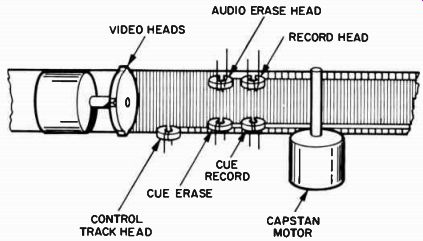
Fig. 2-4. Transverse recording method
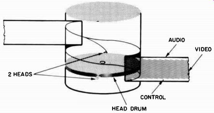
Fig. 2-5. Helical recording method.
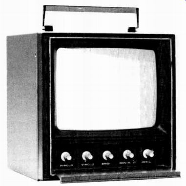
Fig. 2-6. Typical television monitor.
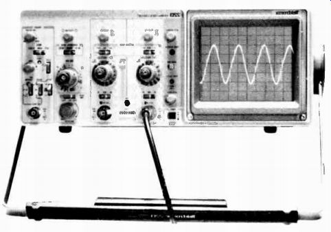
Fig. 2-7. Oscilloscope.
Vidicon The vidicon camera tube (Fig. 2-8) is suitable for black-and white or color television and is used in both broadcasting and closed-circuit applications. The tube consists of an electron gun, beam-focusing electrode (grid 3), fine mesh screen (grid 4), and a target. The electron gun consists of a cathode, control grid (grid 1), and an accelerating grid (grid 2). A low-velocity beam from the electron gun is focused by an external magnetic field and by the electrostatic field of grid 3. Grid 4, which is connected to grid 3, is positioned near the target, which is composed of a transparent conducting film on the inner surface of the faceplate. Each small portion of the photoconductive layer is an insulator when there is no light on the faceplate but becomes slightly conductive when illuminated.
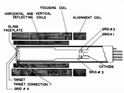
Fig. 2 - 8. Vidicon camera tube.
Grid 4 provides a uniform decelerating field between itself and the photoconductive layer of the target so that the beam approaches the layer perpendicular to it. This condition is necessary for linear scanning. The beam is deflected back and forth and up and down on the target. Since the photoconductive layer has a positive potential, electrons are deposited on it when it is scanned by the beam. This depositing of electrons continues until the surface potential of the photoelectric layer is reduced to that of the cathode. When this point is reached, electrons are turned back to form a return beam that is not used.
Deposits on the scanned surface of any portion of the layer change the difference of potential between the two surfaces of the portion. When the two surfaces of the portion, which, in effect, is a charged capacitor, are connected through the external target circuit and scanning beam, a capacitive current is produced. This current is the video signal.
Transmitter Timing Sync Generator--As explained previously, synchronizing pulses, generated at the transmitter, control the deflection of the electron beams in the camera tube and in the receiver picture tube. The sync generator in the transmitter produces the properly timed and shaped pulses for the horizontal and vertical deflection of the beam in the camera. In addition, these pulses are added to the video signal to keep the receiver in step.
Blanking Generator--The proper pulses are for cutting off the camera and receiver during the retrace period are generated in the blanking generator. These pulses are also added to the video signal before transmission to the receiver.
Vestigial Sideband Filter--As discussed previously, only a portion of the lower sideband is transmitted. A portion of the lower sideband is removed to conserve space in the spectrum. This portion of the signal is removed by the vestigial sideband filter.
Sound Transmitter--The sound transmitter associated with the transmitting system is a conventional frequency-modulation system consisting of audio amplifier, frequency modulator, high frequency transmitter, and high-frequency antenna. Thus, at the transmitting station, there are actually two transmitters: one for the picture signal, and one for the sound.

Fig. 2-9. Block diagram of a television transmission system.
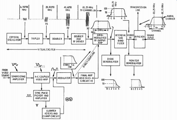
Fig. 2-10. Functional block diagram of a channel-6 transmitter.
Functional Units of a Television Transmitter
A basic block diagram of a television transmitter is shown in Fig. 2-9. The viewfinder is an auxiliary optical and electronic device that is attached to the TV camera to enable the operator to see the same scene that the camera is transducing. A stabilizing amplifier functions to correct faulty video signals from field pickup equipment and transmission characteristics such as noise, switching surges, improper sync-to-signal ratio, and so on. The stabilizing amplifier includes circuits for separating sync signals, wave shapers, sync insertion circuits, and video amplifiers. A vestigial sideband filter is inserted between an AM transmitter and its transmitting antenna to suppress part of one of the side bands. A diplexer is a coupling unit that allows more than one transmitter to operate together on the same antenna.
Next, observe the functional block diagram of a channel-6 TV transmitter, shown in Fig. 2-10; operating frequencies and the chief frequency responses are noted in the diagram. Note that grid modulation is utilized for the picture signal. This form of modulation preserves the de component of the video signal with out undue circuit elaboration. In the studio chain, the dc component of the video signal is reinserted by means of a clamper (dc restorer). Unless the dc component is maintained, night scenes will appear too light and day scenes will appear too dark. As explained subsequently, TV receivers may or may not be designed to preserve the de component of the video signal.
SUMMARY
Videotape recorders are used for many programs. They offer the advantage of being able to record any program for a play back at the desired time. Both sound and picture are included on the magnetic tape and are ready for instant playback because no time is lost in processing.
The most basic type of TV camera tube is the vidicon. The basic function of the camera tube is to convert the variable-light scenes into a varying electrical signal corresponding to the light and dark areas of the picture. Sync generators, blanking generators, vestigial sideband filters, and audio transmitters are all part of the signal transmitted for properly shaped pulses for horizontal and vertical deflection, proper blanking during retrace, and proper sound at the television receiver.
QUIZ
1. What two types of media are used for prerecorded programming?
2. What is the purpose of microwave links?
3. Why are videotape recorders used?
4. Why is a monitor used in transmitting studios?
5. What is the purpose of the sync pulse transmission?
6. What is the purpose of the blanking pulse?
===