In Section 2, a discussion of the various stages in a television transmitter was given. In this Section, the same type of presentation will be given for the television receiver. The function of the television receiver (Fig. 3-1) is to pick up the signal from the television station, amplify it, and employ it to produce visible pictures and audible sound that, in all detail, correspond to the original scene.
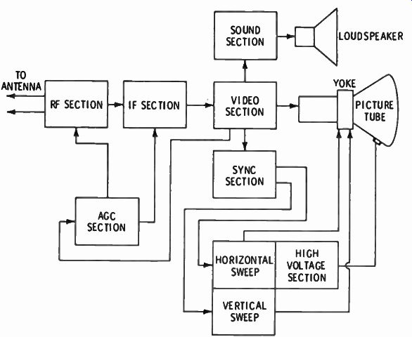
Fig. 3-1. Fundamental block diagram of a television receiver.
In the television receiver, the received signal is amplified and separated into its individual components. These components are amplified and applied in such a way as to produce variations in the intensity of the electron beam of the picture tube. Figure 3-2 depicts the components of the received signal.
Deflection of the beam in the picture tube is accomplished electromagnetically with coils extended to the tube. The oscillators that supply the energy to deflect the beam in the picture tube operate at the same frequency as the deflection circuits in the camera by the sync pulses transmitted as part of the composite video signal.
Thus, the electron beam of the picture tube moves in synchronism with the electron beam of the camera tube, and the variations in brilliance at the point of impact on the picture-tube screen correspond to the illumination on the respective areas of the camera tube. In this manner, the image on the target of the camera tube is dissected, and the information on each element is transmitted separately in a manner that permits the television receiver to take the pulses of information and employ them to produce variations in illuminations on the picture-tube screen.
Since the deflection circuits keep these pulses of illumination in the same respective positions on the screen, a reproduction of the original scene is produced.
(A) Sync pulses and blanking pedestals.
(B) Camera signal.
(C) Sound signal.
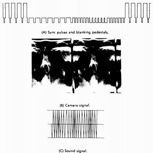
Fig. 3-2. Basic components of the television signal.
BLOCK DIAGRAM OF TELEVISION RECEIVER
It should be understood that all television receivers operate on the same general principles. All use the superheterodyne principle. All must have certain basic stages. The actual circuits may differ, but their function is the same.
In order to simplify the study of television receivers, it is customary to employ block diagrams. When you first look at the circuit of a complete TV receiver, it looks frightening and very complicated. However, by using the block diagram, the complete circuit can be broken down into its individual sections, each of which has its own function.
The block diagram of a television receiver is given in Fig. 3-3.
All the stages, or blocks, shown in Fig. 3-3 are not used in some receivers, depending on their intended price range and application. The blocks shown in dashed lines in Fig. 3-3 are the ones most commonly omitted. Typical stage gain figures for a television receiver are noted in Fig. 3-4.
THE TUNER
Here is how a typical TV receiver works: The signal from the desired VHF TV station and the signals from all other stations in the area arrive at the VHF antenna. All these signals travel down the transmission line to the RF amplifier, which selects only the desired signal and rejects all others. The desired signal is amplified by the RF amplifier and coupled to the mixer. In the mixer stage, the amplified signal from the RF amplifier and a signal from the local oscillator are beat together (heterodyned) to pro duce a lower, or intermediate, frequency. The mixer and the local oscillator are shown in one block in Fig. 3-3 because, in modern TV receivers, these stages are always two portions of the same tube or integrated circuit.
When receiving a UHF signal, the procedure is slightly different. The signals from the UHF station also arrive by antenna and travel down the transmission line. At the UHF tuner, signals from the desired station are selected and applied directly to the mixer stage. Here the signal from the station and the signal from the UHF local oscillator are heterodyned to form the IF frequency.
The IF output from the UHF tuner is then coupled to the VHF RF amplifier. When tuned to the UHF position, the VHF RF amplifier and mixer provide two stages of amplification of the IF signal.
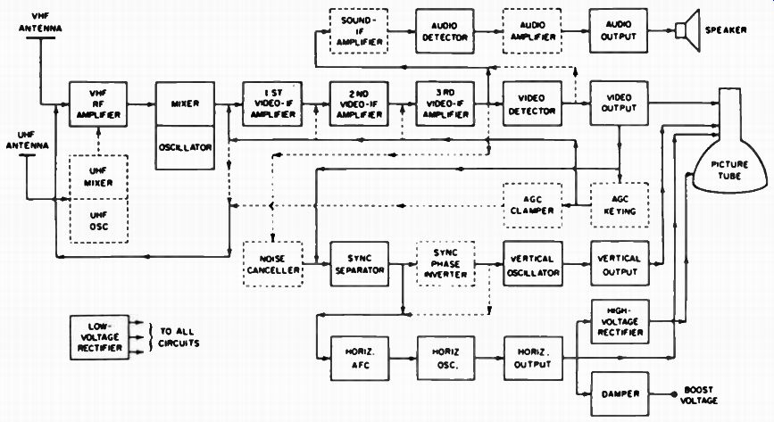
Fig. 3-3. Block diagram of a television receiver.
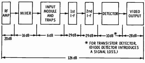
Fig. 3-4. Typical gain figures for a television receiver.
Note that actually two separate IF signals exist at the mixer output. One is produced by the video signal beating with the local oscillator; a typical video IF frequency is 45.75 MHz. The other IF frequency is produced by the sound signal beating with the local oscillator; a typical sound IF frequency is 41.25 MHz.
Thus, the two frequencies are separated by the same 4.5-MHz difference established at the transmitter.
For example, assume that it is desired to tune to a station operating on channel 6, with a video carrier frequency of 83.25 MHz and a sound carrier of 87.75 MHz. The local oscillator frequency in this example would be 129 MHz. Thus, when the local oscillator is heterodyned with the station signals, the following IF frequencies are generated:
Local oscillator
Minus video carrier
Video IF Local oscillator
Minus sound carrier
Sound IF 129.00 MHz 83.25 MHz 45.76 MHz 129.00 MHz 87.75 MHz 41.25 MHz
Notice that, although the sound carrier in the composite video signal is transmitted at the higher frequency, the lower IF is produced by the sound carrier because the oscillator is at a higher frequency than either carrier, and there is an inversion of the frequency relationship between the sound and picture carriers. If the local oscillator were tuned to a frequency lower than the carrier frequencies, the video IF would be lower than the sound IF. Either method will work; however, the former is usually employed because of interface problems that occur when the oscillator is tuned lower than the carrier.
VIDEO IF AMPLIFIER, DETECTOR, AND VIDEO AMPLIFIER
The output of the mixer is coupled to the output of the first video IF amplifier. Remember, the signal at this point contains both video and sound, as well as the sync signals, although the stages are called video (or picture) IF amplifiers. In the early days of TV, the sound was often separated from the video at the mixer output. The term video IF amplifier is a carryover from the days when only the video (and sync) signal was applied to these stages, but in all modern receivers, both video and sound are being amplified by these stages.
The IF amplifiers are tuned to pass a band of frequencies approximately 4 MHz wide and to reject all others. This wide band response is obtained by using various means of coupling between the IF amplifier stages. Thus, the signal in the video IF amplifiers is an RF signal, varying at the video rate, as shown in Fig. 3-5. Three stages of video IF amplification are shown in Fig. 3-3.

Fig. 3-5. Composite video IF signal.
At the output of the last video If amplifier, the signal is coupled to the video detector. The video detector detects, or demodulates, the video IF signal so that a de voltage, which varies in step with the original video and sync signals, is produced at the out put. This signal is shown in Fig. 3-6.
(A) Positive-going sync.
(B) Negative-going sync.
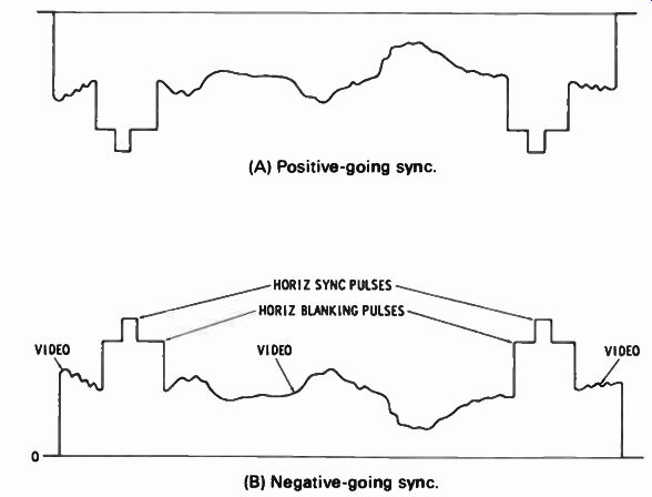
Fig. 3-6. Composite video signal after detection.
In addition to the signal of Fig. 3-6, another signal is produced at the output of the video detector. Recall that, in addition to the video signal, the sound signal is also present in the video IF amplifiers, and that the carrier frequencies for these two signals are separated by 4.5 MHz. These two signals beat together in the video detector, producing a new signal, whose frequency is equal to the 4.5-MHz difference between the signals. This new signal contains all the sound information, and so it is a new sound IF frequency. Because the signal is produced by the beating together of the two signals, it is called the intercarrier sound signal and is always 4.5 MHz. Figure 3-7 shows how a 4.5-MHz signal appears as "fuzz" on the video signal.
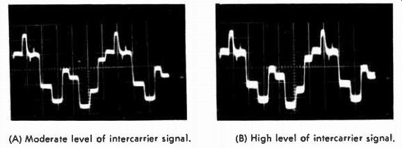
Fig. 3-7. Video signals with a 4.5-MHz, intercarrier-sound signal.
(A) Moderate level of intercarrier signal. (B)
High level of intercarrier signal.
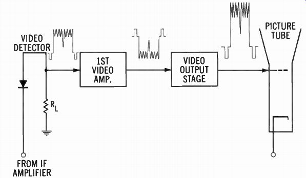
Fig. 3-8. Negative-going sync applied to picture-tube grid.
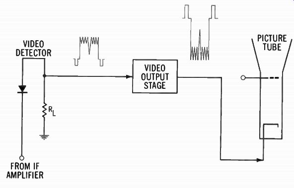
Fig. 3-9. Positive-going sync applied to picture-tube cathode.
The video-output stage follows the video-detector stage. This stage amplifies the weak signal at the detector output for application to the picture tube. The amplified video signal is applied to the picture tube, where it varies the intensity of the beam to produce the light and dark spots on the picture-tube screen.
The blanking pulses must cut the picture tube off. Thus, if a video signal with negative-going sync pulses (Fig. 3-8) is applied the picture tube, the negative portions will reduce the voltage at the grid so that the beam is cut off. When the more positive portions of the signal are applied to the grid, the beam will flow ,from the cathode to the screen in the picture tube. The intensity of the beam at any instant and, hence, the degree of brightness of the spot on the screen will depend upon the instantaneous voltage of the signal; the more positive the signal, the more intense the beam and the brighter the spot on the screen.
If a positive-going sync signal (Fig. 3-9) is applied to the picture tube, the results will still be the same, except that the signal must be applied to the cathode of the picture tube. As the positive-going sync pulses are applied to the picture tube, the instantaneous voltage at the cathode is made more positive, which, if the grid voltage remains constant, is the same as making the grid more negative. In either case, the difference in potential between the two elements is increased; and it is the difference in potential, not the actual voltage, that controls the amount of conduction of the tube. During the negative portions of the signal, the potential on the cathode approaches that of the grid; thus, the tube is allowed to conduct, the amount depending upon the actual voltage difference between the two elements.
In modern television receivers, the signal may be applied to either the grid or the cathode; either polarity is easily obtained.
Recall that each time a signal is amplified by a stage, the polarity of the signal is shifted 180° or reversed. Either a positive- or a negative-going signal can be obtained from the video-detector stage, depending upon the element from which the output is taken. Thus, if the signal has negative-going sync at the detector output and is amplified by a single video-detector stage, positive going sync pulses will be applied to the picture tube. This is the correct polarity for application to the cathode of the picture tube.
However, if two stages of video amplification are employed, the signal will again be shifted 180°, making the sync pulse polarity negative, the correct polarity for applying to the grid of the picture tube. If a positive-going sync signal is obtained from the video detector, the situation is reversed. With a single video amplifier stage, the signal is correct for applying to the grid of the picture tube; with two stages of video amplification, the proper signal for application to the cathode of the picture tube is obtained.
(A) Both following video output.
(B) Both preceding video output
(C) Sound take-off preceding and sync take-off following video output.
(D) Sound take-off following and sync take-off preceding video output.
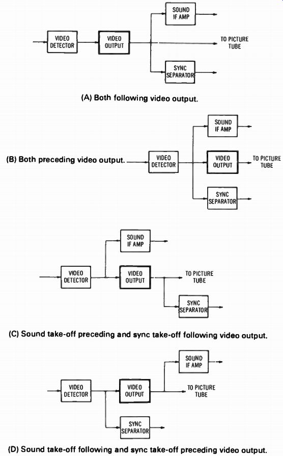
Fig. 3-10. Four methods of sync and sound takeoffs.
SOUND SECTION
Recall that at the output of the video detector, a 4.5-MHz signal that was frequency modulated with the audio (sound) signal was produced. Sometimes, the sound signal is removed directly following the video detector, and sometimes it is further amplified by the video amplifier before removal. Four methods of sound and sync signal takeoff are shown in Fig. 3-10.
As indicated by the dashed-line box in Fig. 3-3, the sound IF amplifier may or may not be included in the circuit. From this point on, the sound section is very similar to that of an FM radio.
The signal is detected by the audio detector, and the audio signal, which corresponds to the original sounds at the transmitter, appears. This signal is amplified by the audio amplifier and audio-output stages, and it is applied to the speaker where the electrical signal is converted to audible sound. Notice, in Fig. 3-3, the audio amplifier is sometimes omitted. When this stage is omitted, audio amplification is provided by the audio detector in addition to the detector action.
The sound system just described is called the intercarrier system. In this system the sound IF is always 4.5 MHz-the difference between the sound and video carriers. This system is employed in all present-day television receivers. In early receivers, the sound IF signal was removed at the mixer output or at some point in the video IF (usually in the 20-MHz region). In systems employing this type of sound circuits, two or more sound IF amplifier stages are used. Otherwise, the frequency of the IF is the only difference between the dual-channel and intercarrier systems.
AGC CIRCUIT
Just as an automatic-volume-control (AVC) circuit is employed in radios to compensate for changes in the strength of the received signal, some means must be included in TV receivers to compensate for changes in signal strength. In Fig. 3-3, a portion of the signal from the video output is coupled to the automatic gain-control (AGC) keying. This stage samples the amplitude of the signal and produces a bias voltage for the RF and video IF amplifiers. This bias voltage controls the gain of these stages so that the output signal is fairly constant, even though the input signal varies in strength.
In the keyed AGC system, the amplitude of the video signal is checked only during the period of the horizontal sync pulse.
Unlike the video signal, the horizontal sync pulse is always transmitted at a constant level. Therefore keying the AGC voltage to the horizontal sync pulse provides a constant checkpoint.
The plan of a keyed AGC system is shown in Fig. 3-11.
In other systems, no keying pulse is used. In this type of circuit, the entire video signal is used as the reference. The circuit is then called the AGC amplifier. Sometimes, a combination of resistors and capacitors provides the AGC voltage.
An AGC clamper stage is also shown in dashed lines in Fig. 3-3, indicating that it may not be used in all receivers. This stage removes the AGC voltage from the RF amplifier, allowing it to operate at a full gain until the signal reaches a predetermined level. When this level is reached, the circuit cuts out and allows the normal AGC voltage to be applied to the RF amplifier. An AGC clamp is also shown in Fig. 3-11.
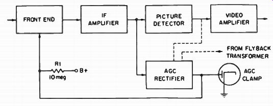
Fig. 3-11. Plan of a keyed AGC system.
SYNC CIRCUITS
Up to this point, we have said nothing about deflection. We now have the video (picture) signal displayed on the screen and sound emerging from the speaker. In addition, a means has been provided for varying the gain of the receiver so that we have a nearly constant amplitude signal at the picture tube. Now, some means must be provided to deflect this beam back and forth and up and down on the screen exactly in step with the beam in the camera tube at the transmitter.
A portion of the video signal at the video-output stage is coupled to the sync separator. Here the horizontal and vertical sync pulses are separated from the video signal. From the sync separator, the horizontal sync pulses are coupled to the horizontal deflection circuit and the vertical sync pulses are coupled to the vertical deflection circuit. These pulses serve to start each line or field exactly in step with the beam at the transmitter. A noise canceller stage is often included to prevent any noise pulses in the signal from being coupled to the deflection circuit and causing improper triggering of these circuits. Fig. 3-12 shows what is meant by separated, or "stripped," sync pulses.
A sync-phase inverter may also be included in some receivers.
When used, this stage reverses the polarity of the signal so that it will be the proper phase to trigger the deflection circuits. Figure 3-13 is a block diagram of a horizontal AFC and deflection system.
(A) The appearance of the vertical sync pulse or -hammerhead" on the picture tube screen.
(B) Separated or stripped sync pulse.
(C) The build-up of the hammerhead (D) The pulses that comprise the from sync pulse, ammerhead.
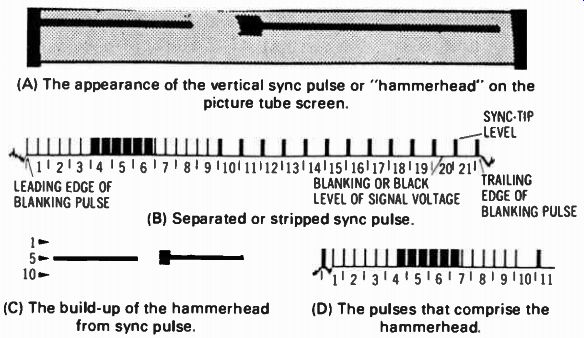
Fig. 3-12. Stripped sync pulses.
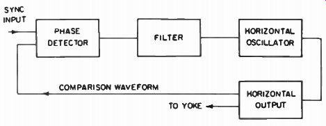
Fig. 3-13. Block diagram of a horizontal AFC and deflection system.
DEFLECTION CIRCUITS
The vertical sync pulses are coupled to the vertical oscillator, which generates a signal at a 60-cycle vertical rate. The sync pulses trigger the vertical oscillator so that each cycle will start exactly in step with the transmitted signal The output of the vertical oscillator is coupled to the vertical output stage, where it is boosted in amplitude to the proper level to provide vertical deflection of the electron beam.
The horizontal sync pulses are not coupled directly to the horizontal oscillator. Instead, they are first sent to the horizontal automatic-frequency-control (AFC) stage. The AFC then provides a correction voltage for the horizontal oscillator to keep it exactly in step with the horizontal scanning rate at the transmit ter. The primary purpose of the AFC stage is to provide greater immunity to noise pulses that might enter with the horizontal sync pulses.
Like the vertical circuit, the horizontal oscillator generates a signal that is amplified by the horizontal output stage. The amplified signal is coupled to the horizontal deflection coils of the picture tube, where it traces the individual horizontal lines across the screen.
The damper is shown connected to the horizontal output stage in Fig. 3-3. During the horizontal retrace period, when the beam is returning from the right to the left of the screen, undesired oscillations would be set up in the horizontal output transformer unless something is done to suppress them. Figure 3-14 shows the appearance of ringing bars. The damper squelches, or clamps out, these oscillations. It also permits the deflection-coil current to decay at a uniform rate so that the left side of the screen will be linear, not distorted.
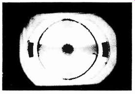
Fig. 3-14. Ringing bars at the left side of the raster.
Note that it was stated that both the vertical and horizontal oscillators generated a signal. The sync pulse is not necessary for the stages to operate. The only purpose of the sync pulses is to keep the circuits operating exactly in step with the ones at the transmitter.
POWER SUPPLIES
Two separate power supplies plus an additional voltage source derived from the damper circuit are used in all television receivers.
Low-Voltage Supply
The low-voltage power supply provides the voltage necessary for operation of practically every tube in the TV receiver. This circuit is much like the power supply of a radio or amplifier. It takes the alternating current from the line, rectifies it, and sup plies the de B+ voltages necessary to operate the tubes in the TV receiver. Of course, since there are many more tubes in a TV receiver, the TV power supply must be capable of supplying a much higher current than a radio. In addition, the voltage is usually stepped up to a higher value in a TV receiver. Typical B+ voltages in TV receivers range from 125 to 300 volts.
Because all circuits do not require the same operating voltages, a voltage divider is usually connected at the output of the power supply. The different circuits are then connected to the points that supply the proper operating voltages. In addition to the B+ voltages, the low-voltage supply also furnishes the filament voltage necessary to heat the tubes to the proper operating point and, in some receivers, the negative bias voltages. A variation of this supply is now used for "solid state" TV receivers.
High-Voltage Supply
In addition to the B+ voltages, a much higher voltage (15,000 to 23,000 volts) is needed for proper operation of the picture tube.
This voltage is obtained from the horizontal deflection circuits.
The pulse from the horizontal output stage is stepped up by the horizontal output and high-voltage transformer to a very high value. Then this pulse is rectified by the high-voltage rectifier to provide the high dc voltage. Since very little current is necessary, this high voltage can be obtained from the horizontal output stage without placing too much strain on the stage. Nevertheless, the horizontal output stage is the highest-powered stage in the receiver.
Boost Voltage
Another voltage, called the boost voltage, is obtained from the damper stage. The normal damper action of suppressing the pulse in the horizontal output stage results in a voltage higher than the normal B+ developed in the circuit. This voltage is filtered and put to work in the receiver. In modern TV receivers, the boost voltage is employed as the B+ for the horizontal output tube. In addition, it may also be applied to the vertical output, horizontal oscillator, picture tube, and other stages of the receiver as needed.
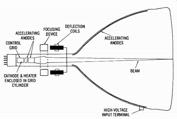
Fig. 3-15. Magnetically controlled cathode-ray tube.
PICTURE TUBE
Now that all the signals have been properly amplified and processed, let us examine the picture tube (Fig. 3-15). The basic operation of the picture tube is the same as for any other tube; that is, a filament (heater) heats the cathode, which emits electrons. These electrons are attracted by the accelerating anodes, which have B+ voltage on them, and by the second anode, which has the high voltage connected to it. However, instead of striking these elements, the electrons travel to the face of the tube and strike the screen. The screen is coated with a fluorescent material that glows when struck by the electrons. This is the lighted portion you see on the screen.
The magnetic field from the focusing devices concentrates all the electrons in the beam so they strike the screen at one point. A magnetic focusing device, connected around the neck of the tube, is shown in Fig. 3-15. In many receivers, however, this function is accomplished by another element within the picture tube.
The horizontal and vertical deflection currents are applied to the deflection coils shown on the neck of the tube. These cur rents, flowing through the coils, cause a magnetic field to be produced, which acts upon the electron beam in the tube. These vertical deflection currents cause the beam to be deflected upward or downward from the center of the screen. The deflection is at the 60-hertz rate. At the same time, the horizontal deflection currents cause the beam to be deflected to the left and right at the 15,750-hertz rate. Thus, the beam is caused to scan across the face of the tube from left to right and from top to bottom, in step with the beam at the transmitter.
The video signal is applied to the grid or cathode, as explained previously. The element that has no signal applied to it is connected to a constant-voltage source. As the video signal varies, more or fewer electrons are allowed to pass. When more electrons pass, the beam produces a brighter spot on the particular spot being scanned at that instant on the screen. When fewer electrons pass, fewer electrons strike the screen; hence, a darker spot will be produced at that instant.
Recall that the vertical and horizontal oscillators generate a deflection signal; only the timing of these signals is controlled by the sync pulses. When no video signal is applied to the grid or cathode of the picture tube, the deflection currents will still flow in the deflection coils and the beam will still be deflected back and forth and up and down on the screen. The only difference is that the electrons striking the screen will not form alternate lighter and darker areas. Instead, a constant brightness pattern will be produced. This series of horizontal lines across the tube screen is called the raster and is present whether a picture is being produced or not.
This completes the "block diagram" discussion of the TV receiver. In later Sections, the circuits employed in the individual "blocks" will be examined, but in this Section we attempted to give the reader an understanding of the overall operation of the receiver and how the individual blocks fit together to produce the desired results. Figure 3-16 gives an overview of the basic TV troubleshooting procedures.
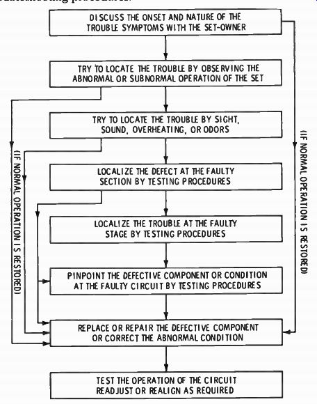
Fig. 3-16. Overview of basic troubleshooting procedures.
SUMMARY
The function of the television receiver is to pick up the signal from the television station, amplify it, and produce a visible picture and audible sound corresponding to the original scene.
In the television receiver, the signal is received, amplified, and separated into its individual components. Deflection of the beam in the picture tube is accomplished electromagnetically with coils that are external to the tube. The deflection circuits in the receiver are kept in step with the deflection circuits in the camera by the sync pulses transmitted as part of the composite video signal.
The signals from the desired VHF or UHF television station arrive at the television receiver antenna. These signals travel down the antenna line to the RF amplifier, where only the desired signal is selected and all others are rejected. The desired signal is amplified by the RF amplifier and coupled to the mixer.
In the mixer stage the amplified signal from the RF amplifier and the signal from the local oscillator are beat together to produce a lower, or intermediate, frequency.
The output of the mixer is coupled to the input of the first video IF amplifier. At this point the signal still contains both video and sound, as well as the sync signals. The IF amplifiers are tuned to pass a band of frequencies approximately 4 MHz wide.
QUIZ
1. What is the purpose of the television receiver?
2. Explain the basic operation of the television receiver.
3. What is the typical video IF frequency?
4. What is the typical sound IF frequency?
5. What separates the sound present in the video IF amplifier?
6. What is meant by intercarrier?
7. What is the purpose of the low-voltage and high-voltage supply?
8. What is the source for high-voltage?
===