The first step in any antenna installation is a survey of the location. Look over the building. Note the type of construction (brick, stone, frame, etc.) and the type of roof. Check the location of the TV receiver(s) to be served by the antenna. Decide on the best location for the antenna and the best route for the lead in. Sometimes the best location for an antenna will be determined by the availability of a good ground. An example of an antenna grounding arrangement is shown in Fig. 5-1. Observe that the mast is grounded directly, and that the lead-in is connected to the ground. A short and direct connection to an external ground is required by the National Electrical Code and by local electrical codes.
The actual selection of the type of antenna to be installed will depend on many factors. The distance from the transmitting antenna is of prime importance. Another important factor is the number of channels available. As discussed in Section 4, some antennas are suitable for strong signal areas, some are suitable for all-channel reception, and others for only a single channel. Look around and see what types of antennas are used on neighborhood houses; but before installing one of the same type, make sure they are obtaining suitable reception.
Most homes have two or more TV sets. Where it is practical, it is logical to use one antenna to serve every set in the house.
Figure 5-2 shows the simplest way in which this is done-by using a multi-set coupler. In other cases, people want a TV antenna outlet in every room. This requirement is served best by a home TV system such as depicted in Fig. 5-3. (Technical details are explained later in this Section.)
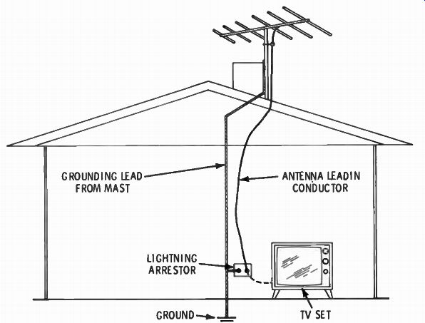
Fig. 5-1. Example of antenna-grounding arrangement.
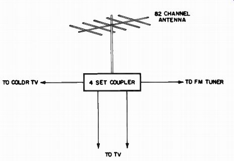
Fig. 5-2. Antenna-coupler splitter.
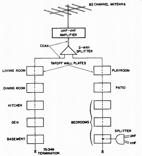
Fig. 5-3. Small master antenna system.
TOOLS
Of course, one of the first tools needed in any antenna installation is a ladder. Usually a 20- or 24-foot extension ladder is best.
Several hand tools are also necessary. No attempt will be made to list all the possible tools that may be needed. Each installation job varies, and so do the tool requirements. However, the following are considered the basic tools required before any installation is attempted:
1. Assortment of screwdrivers
2. Slip-joint pliers
3. Long-nose pliers
4. Diagonal cutting pliers
5. 6-in, case-hardened cutters (for bolts, guy wire, etc.)
6. Open-end wrenches
7. Nut drivers ( 1/4, 3/8, 5/16, 7/16, and 1/2 in.)
8. Hammer
9. Assortment of wood bits
10. Bell-hangers bit ( 3/8 in. by at least 12 in. long)
11. Brace for bits
In addition, there are many other useful tools. Socket wrenches are often handy, as is a small adjustable wrench. Also, a hacksaw and small keyhole saw are often needed. Although not a necessity, a 1/4 - or 3/8-in. electric drill is very handy. A long extension cord will be needed for the drill.
If the house is of brick or masonry construction, some means of drilling a hole in the wall must be available. A star drill (Fig. 5-4) can be used. This type of drill is hit with a hammer and rotated slightly after each stroke. A much easier method of drilling a hole is provided by the carbide-tipped masonry drill bit shown in Fig. 5-5. This bit fits in the 1/4 -in. electric drill (be sure to get a bit with a 1/4 -in. shank). One word of caution: Don't force the bit in the masonry-take your time.
MASTS AND TOWERS
Another decision that must be made in the initial inspection is how to support the antenna. Again, one of the primary factors in determining the selection is the distance from the transmitting antenna. In strong-signal areas almost any type of installation can be used. In fringe areas, tall towers may be necessary.
Fig. 5-4. Two types of star drills.
Fig. 5-5. Carbide-tipped masonry bit.
Masts
The tubular mast is the most popular method of supporting an antenna. It can be mounted on a chimney, or the peak of a roof, from a flat roof, attached to the side of the building, or even hung in the attic (see Fig. 5-6). Tubular masts are made of aluminum or steel and are usually sold in 10-ft. lengths. The ends are made so that one end slips into the opposite end of another section to obtain greater heights. If properly guyed, masts up to 50 ft. can be employed.
Telescopic masts are also available. In this type of construction, each section fits inside the next lower section. When a section is extended, a locking mechanism holds it in place. Telescopic masts are available up to 50 ft. in length. (See Fig. 5-7.)
Towers
Where greater heights or a sturdier installation is necessary, the triangular steel tower is used. Towers are available in 6- or 10-ft.
sections that are bolted together to obtain the necessary height. A typical fringe-area installation utilizing a tower is shown in Fig. 5-8.
Another type of tower is hinged in the middle and has a built-in winch that is used to tilt the top over to gain access to the antenna. In still a different type of tower, each section gets progressively smaller as it approaches the top, and each section fits inside the next lower section. Thus the entire tower is telescoped together and is raised and lowered by a built-in winch at the base.
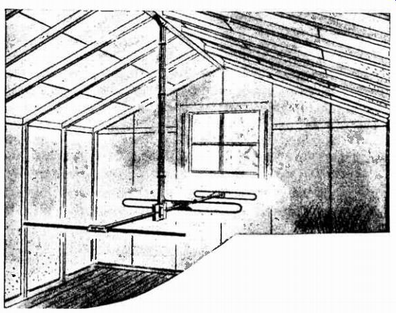
Fig. 5-6. Typical attic installation.
Fig. 5-7. Telescopic mast detail.
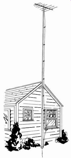
Fig. 5-8. Typical fringe-area antenna installation.
Locating the Antenna
Before attempting to install the antenna, it is essential to care fully select a position that allows the following conditions to be fulfilled:
1. Absence of obstruction, such as buildings, trees, power lines, other nearby antenna systems, etc., between the pro posed antenna site and the transmitting antenna.
2. Maximum distance between proposed antenna sites and sources of electrical noise such as might originate in ignition systems, elevator relays, diathermy and x-ray machines, and arcing from electrical transmit systems. Several of these conditions preclude the possibility of mounting the antenna near the edge of a roof adjoining a street with heavy traffic even though this site may be preferable with respect to length of antenna lead-in.
3. Greatest possible height above ground level. In general, this will allow the antenna to overcome such obstructions as mentioned in item 1.
Before the mast or tower is actually installed, a preliminary check of the location choice should be made. Temporarily connect the antenna to a mast, and attach the transmission line. Connect the transmission line to the TV receiver, and hold the antenna in the chosen location to determine if a suitable signal is obtained.
It is often possible to obtain considerable improvement in performance by moving the antenna location a small distance from the original site. This final test for the most desirable antenna location becomes vitally important in areas where signal strength is low or where reflection from surrounding surfaces produces multiple transmission paths, thereby creating multiple images, or "ghosts," on the screen.
By now it should be obvious that an antenna installation requires two people. One can hold the antenna while the other observes the effect on the screen. Some means of communication between the two is necessary. "Walkie-talkies" or wireless, two way headset radios are very helpful for this purpose. Lacking this, a third person can stand outside a window or door and relay the message between the person at the antenna and the one observing the receiver.
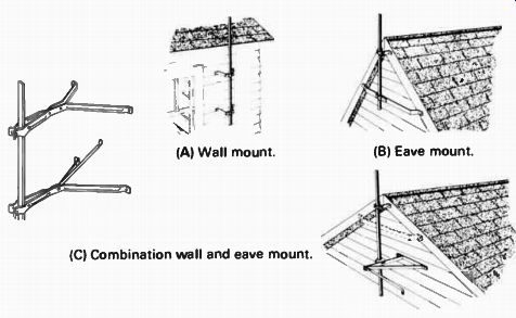
Fig. 5-9. Wall and eave mounts. (A) Wall mount. (B) Eave mount. (C) Combination
wall and eave mount.
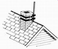
Fig. 5-10. Chimney mount.
Mast Installation
Various methods are used for mounting antenna masts. For short masts, brackets can be used to attach the mast to the wall or eave, as shown in Fig. 5-9. In addition, there are many versions of the chimney mount (Fig. 5-10). Before the mountings shown in Figs. 5-9 and 5-10 are attempted, be sure to check the wall or chimney. Make sure they are in good condition so that they will be able to withstand the added strain placed on them by the antenna. During a windstorm or in the winter in the northern areas, when the antenna and mast are coated with ice, enormous pressures are exerted on the installation.
The spacing between the brackets should be sufficient to hold the mast rigid. This distance will vary with the mast height. A mast support suitable for a peaked roof is shown in Fig. 5-11.
Supports very similar to this can also be used for flat roofs.
Masts can also be based on the ground and extended above the roof top. Some method of solid support must be provided at the base. This support can be provided by a cement block, solid board, or even a flat rock. A pipe strap should be placed around the mast at the eave or gable of the house. If the mast does not extend for more than 10 ft. above this point, no additional sup ports are required. Enough slack should be allowed in the strap to enable the mast to be turned during installation. The strap should exert enough pressure on the mast to prevent the wind from twisting the antenna upon completion. Thus, orientation of the antenna is simplified. This type of installation is popular and easy to make. Telescopic masts, which are available in heights up to 40 ft., are usually employed.
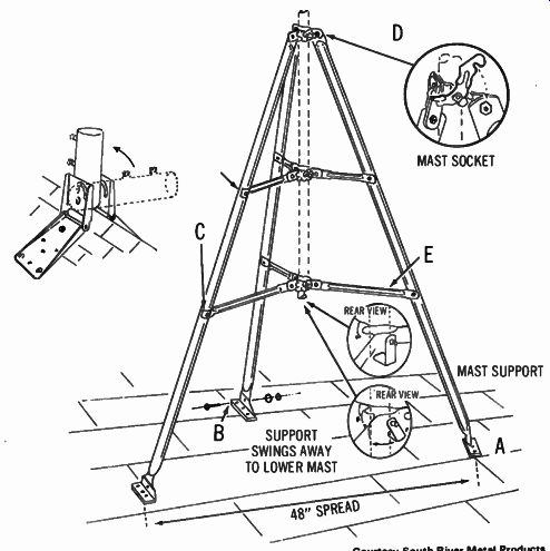
Fig. 5-11. Antenna mount suitable for a peaked roof.
Fig. 5-12. Safety belt worn while working on a tower.
Tower Installation
Like masts, towers can be mounted on the roof or on the ground; however, the ground installation is more popular because of the difficulty in manipulating the tower on a roof. Perhaps the easiest method is to assemble the tower on the ground and attach the antenna and transmission line. Then, with one person on the roof and two on the ground, the antenna is lifted into position.
Sometimes, however, it is necessary to install the tower section while the installer climbs the tower. Guy wires should be installed in their proper locations before the installer attempts to climb the tower (see the following section). Never attempt to climb an unsupported tower. A safety belt is a necessity when working on a tower because both hands will be needed for connecting the sections. In addition, some means must be employed to raise the sections for the person on the tower. Gin poles (Fig. 5-12) are available for this purpose.
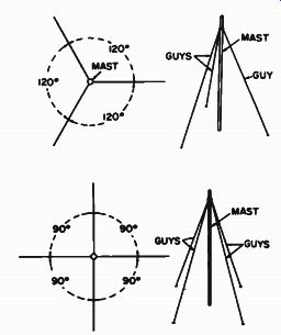
Fig. 5-13. Method of placing three guy wires.

Fig. 5-14. Method of placing four guy wires.
Guy Wires
Guy wires must be attached to practically every antenna installation to support the mast or tower. The only exceptions are self-supporting steel towers set deep in concrete and eave installations, which extend only a few feet above the roof.
The most popular guy wire is 6/20 steel (6 strands of No. 20-gage steel wire). Heavier wires, such as 6/18 and 6/14, are also available; and sometimes aluminum wire is used. Three or four guy wires should be used at each guying point. In the three-guy system (Fig. 5-13), guy wires are spaced approximately 120° apart; while in the four-guy system (Fig. 5-14), the spacing is approximately 90°. The actual spacing between guy wires must depend upon the physical layout of the location.
In general, separate guy-wire systems should be attached for each 10 ft. of height for masts; for towers, guy wires should be attached for each 10 or 12 ft. of height. In either case, they can be spaced closer if necessary. In areas where high wind velocities or severe winters are expected, extra guy wires are indicated.
Rings that fit over the mast are available for attaching the guy wires. For towers, rings that fit over each leg are used; they should be slipped over the legs as the tower is assembled.
The type of anchor used at the opposite end of the guy wire will depend on the location. Flat steel plates with one end bent up at approximately a 45° angle should be used for anchoring guy wire on walls or flat surfaces. Screw-in eyes are available for roof installations. Special screw auger stakes are available for use in the ground.
Do not attach the guy wire directly to the ring on the mast or tower or the anchorage. Instead a thimble should be inserted first. The wire is inserted around the thimble and twisted as shown in Fig. 5-15. When the guy wire is attached in this manner, there are no exposed sharp edges to cut into the wire and weaken the installation.
TRANSMISSION LINES
A properly selected and installed transmission line is as important to the quality of the antenna system as the antenna itself. An improperly installed line causes reflection (ghosts) and high losses. Reflections in the line make it impossible to obtain clear pictures; and in severe cases, the reflections cause "smears" so that the picture appears out of focus even though the receiver is perfectly focused. In general, the longer the transmission line, the more care required in installation.
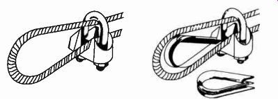
Fig. 5-15. Use of a guy-wire thimble.
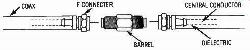
Fig. 5-16. Proper method of splicing coax cable.
Most television receivers have a 300-ohm input circuit, which is intended for connection to a 300-ohm antenna system. Failure to observe proper impedance match between antenna, transmission line, and receiver will result in less energy delivered to the receiver, and undesirable effects of noise and interference may be accentuated.
Types of Transmission Line
A 75-ohm, shielded coax transmission line is now the accepted installation cable, replacing 300-ohm, low-loss transmission line.
Since coaxial cable normally is not available with a 300-ohm impedance, impedance-matching devices should be used.
Length of Line--The length of the transmission line should be kept as short as possible. The longer the line, the greater the opportunity for man-made electrical disturbances to introduce undesirable effects. In addition, attenuation of the line, although low, will reduce the energy fed to the receiver in direct proportion to length.
Splicing the Line--If it becomes necessary to splice on an additional length of coax cable, care should be exercised to avoid a mismatch or short at the splice. The user of F connectors and a female-to-female "barrel" connector is recommended to complete the splice. (See Fig. 5-16.) Routing and Securing--It is well to carefully consider the best route for the transmission line with respect to length and electrical disturbance shielding. A compromise must usually be made on the length so as to be able to take advantage of the shielding effect of the building against such disturbances as ignition noise and arcing from electrical transit systems. Whenever possible, the line should be run in a vertical direction so that rain, sleet, and snow will have less tendency to cling to it. If a horizontal run is necessary, it should be made under an eave or other protection.
The standoff insulators shown in Fig. 5-17 are designed for mounting in wood (left) or on the mast (right). Other types of standoffs are constructed for mounting in almost any surface; there is even one for driving into cement walls. Shafts of various lengths are also available to suit any need.
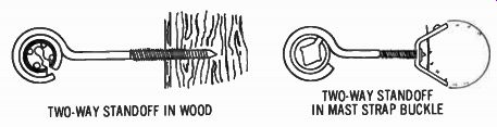
Fig. 5-17. Standoff insulators. TWO-WAY STANDOFF IN WOOD TWO-WAY STANDOFF IN
MAST STRAP BUCKLE. Courtesy South River Metal Products
Standoff insulators should be placed approximately 5 ft. apart along the line. However, the actual locations will depend upon the location of physical obstructions and the route the line must take. The insulator should grip the transmission line and support it in both the vertical and horizontal directions. To attach the line to the standoff, insert the line in the slot and then twist the inner insulating material so that the slot opening is positioned at the rear of the metal eye, as shown in Fig. 5-18. The line should be pulled tight so that a heavy wind will not cause it to swing against surrounding objects, and then the metal eye should be squeezed so that it tightly grips the inner insulator (hence the line), preventing it from moving.
Courtesy South River Metal Products
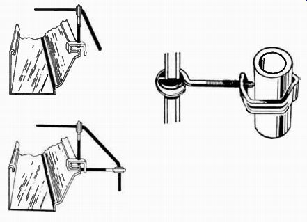
Fig. 5-18. Method of placing transmission line in standoff insulator.
Other types of mountings are now available, developed by the CATV industry (Fig. 5-19). They include plastic nail-in anchors, siding push clips, and, for wood surfaces, a round crown stapler.
Care must be exercised in the selection of these anchors. The anchor diameter must match the diameter of the coax to avoid crushing the dielectric and therefore affecting the characteristics of the coax cable. Direct attachment to the structure below the roof line prevents the danger of protruding obstructions to the occupants of the structure, prevents "wind whipping," and provides a more pleasing appearance.
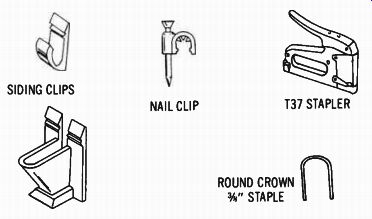
Fig. 5-19. Attachments developed by the CATV industry.
Entering the House
Various methods are employed for entering the house. Of course, the window can be raised, the coax inserted, and the window lowered. However, this method is far from satisfactory.
If the window is metal or if metal flashing is employed along the window, the metal will create a short across the conductors of the coax, thus shorting out the antenna. In addition, raising and lowering the window will wear away the insulation and allow moisture to gain access to the cable (not to mention the heat loss to the house).
Special entrance fittings are available. A 1/2 -in. hole is drilled through the wall, and the device inserted. The coax is then inserted through the device, which also seals the hole to prevent cold or rain from entering. Such a device can be installed directly behind the desired location for the receiver. The receiver will hide the entrance fitting from view. Some devices are equipped with a socket at the inside end for attaching the coax to the receiver.
Another method of entering the house is under the floor through a ventilation opening or hole drilled for this purpose.
The lead-in is then run under the house to the desired location.
When routing the coax inside or under the home, it should be routed by the shortest possible path to the receiver, taking special precaution to avoid contact with pipes, radiators, or other metal objects.
Special wall plugs can be used as a means for connecting the transmission line to the receiver. The lead-in can be run under the floor or in the attic to a point directly below (or above) the desired location. Then a hole is drilled between the walls, and a cutout is made for the wall receptacle. The lead-in is routed through the hole to the receptacle opening. This procedure is commonly used in prewiring of a house or commercial structure where exposed wires are not desirable.
In addition to the TV-antenna outlet, antenna receptacles may also provide outlets for rotator cables or an FM antenna. The unit shown in Fig. 5-20 has an outlet for the TV and an FM antenna.
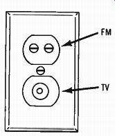
Fig. 5-20. Combination TV- and FM-antenna wall socket.
Outlets can be installed at several locations within the house.
However, if more than one receiver is to be operated at once, some means of isolation is usually necessary. A splitter, or tap, may be used to provide a multiple connection and isolation point.
Even when only one receiver is being used at one time, the length of the transmission line to the other outlets may sometimes cause an adverse effect on the signal.
Connecting Line to Receiver
Depending on the year of manufacture, a terminal strip or a female F connector or barrel will be found on the rear of the receiver cabinet. The 300-ohm lead-in may be connected directly to the terminals marked VHF. A 75-ohm coax lead may be connected directly to the female F connector, or a balun may be employed to match the impedance of the terminal strip. If the antenna is an all-channel antenna, a VHF-UHF splitter will be required to feed both the VHF and UHF inputs. When a wall plate is used, a short length of transmission line must be fabricated with a plug or connector that matches the wall plate.
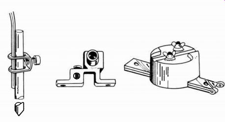
Fig. 5-21. Typical lightning arrestors, grounding blocks, and grounding rod.
GROUNDING
No antenna installation is complete until it has been properly grounded. Unless the mast or tower is buried in the ground, a ground wire must be run from it to a suitable ground. Cold-water pipes, underground tanks, or other metallic underground systems are considered suitable grounds. A ground rod can be driven in the ground and connected to the tower. Such a rod should be a 5/8 -in.-diameter, 8-ft.-long, copper-plated steel rod.
In addition, a lightning arrester should be placed at the point where the lead-in enters the building. Numerous approved types are available. All have some means whereby two contacts are placed in close proximity to the line (Fig. 5-21). Then a ground wire is run from another terminal to the ground rod. The National Electrical Code states that separate grounds should be employed for each portion of the system. However, if the lightning arrester is connected directly to the mast or tower, a single ground can be used. In addition, where separate grounds are employed, each of these separate grounds should be connected together by a separate interconnecting ground wire.
Always leave a loop between the last standoff or lightning arrester and the point where lead-in enters the house, as shown in Fig. 5-22. This loop prevents water from running down the line and inside the house.
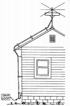
Fig. 5-22. Drip loop in the antenna lead-in.
-------------
CODE SPECIFICATIONS
Articles 810 and 820 of the National Electrical Code give the specifications for safe installation of antenna systems for radio and television receivers. Portions of this code are now given.
ARTICLE 810-RADIO AND TELEVISION EQUIPMENT-RECEIVING EQUIPMENT-ANTENNA SYSTEMS
810-11. Material. Antennas and lead-in conductors shall be of hard-drawn copper, bronze, aluminum alloy, copper-clad steel or other high strength, corrosion-resistant material. Soft-drawn or medium-drawn copper may be used for lead-in conductors where the maximum span between points of support is less than 35 feet.
810-12. Support. Outdoor antennas and lead-in conductors shall be securely supported. The antennas shall not be attached to electric service mast. They shall not be attached to poles or similar structures carrying electric light or power wires or trolley wires of more than 250 volts. Insulators supporting the antenna conductors shall have sufficient mechanical strength to safely support the conductors.
Lead-in conductors shall be securely attached to the antenna.
810-813. Avoidance of Contacts with Conductors of Other Systems. Outdoor antennas and lead-in conductors from an antenna to building shall not cross over electrical light or power circuits and shall be kept well away from all such circuits so as to avoid the possibility of accidental contact. Where proximity to electric light and power service conductors of less than 250 volts cannot be avoided, the installation shall be such as to provide a clearance of at least 2 feet. Where practicable, antenna conductors shall be so installed as not to cross under electric light or power conductors.
810-14. Splices. Splices and joints in antenna spans shall be made with approved splicing devices or by such other means as will not appreciably weaken conductors. (Soldering may ordinarily be expected to weaken conductors. Therefore, the joint should be mechanically secure before soldering.) 810-15. Grounding. Masts and metal structures supporting antennas shall be grounded in accordance with Section 810-21.
810-16. (b) Self-Supporting Antennas. Outdoor antennas, such as vertical rods or dipole structures, shall be of non-corrodible materials and of strength suitable to withstand ice and loading conditions, and shall be located well away from overhead conductors of electric light and power circuits of over 150 volts to ground so as to avoid the possibility of the antenna structure falling into or accidental contact with such circuits.
810-18. Clearances-Receiving Stations. (a) On Outside of Buildings. Lead-in conductors attached to buildings shall be so installed that they cannot swing closer than 2 feet to the conductors of circuits of 250 volts, or less between conductors, or 10 feet to conductors of circuits of more than 250 volts between conductors, where if all conductors involved are supported so as to insure permanent separation, the clearance may be reduced but shall not be less than 4 inches. The clearance between lead-in conductors and any conductor forming a part of a lightning-rod system shall be not less than 8 feet unless the bonding referred to in Section 2588 is accomplished. (b) Antennas and Lead-Ins-Indoors. Indoor antennas and indoor lead-ins shall not be run nearer than 2 inches to conductors of other winding systems in the premises unless, (1) such other conductors are in metal raceways or cable armor, or, (2) unless permanently separated from such other conductors by a continuous and firmly fixed nonconductor such as porcelain tubes or flexible tubing.
810-20. Antenna Discharge Units (Lightning Arrestor)-Receiving Stations. (a) Where Required. Each conductor of a lead-in from an outdoor antenna shall be provided with a listed antenna discharge unit unless the lead-in conductors are enclosed in a continuous metallic shield that is either permanently and effectively grounded, or is protected by an antenna discharge unit. (b) Location Antenna discharge units shall be located outside the building, or inside the building between the point of entrance of the lead-in and the television set or transformers, and as near as practicable to the entrance of the conductors to the building. The antenna discharge unit shall not be located near combustible material nor in a hazardous location.
810-21. Grounding Conductors-Receiving Stations. (a) Material. The grounding conductor shall, unless otherwise specified, be of copper, aluminum, copper clad steel, bronze, or other similar corrosion-resistant material. (e) Run in Straight Line The grounding conductor for an antenna mast or antenna discharge unit shall be run in as straight a line as practicable from the mast and/or discharge unit to the grounding electrode.
810-27. Grounding Conductors-Receiving Stations. (g) Inside or Outside Building. The grounding conductor may be run either inside or outside the building.
(h) Size. The grounding conductor shall be not smaller than No. 10 copper, No. 8 aluminum, or No. 17 copper-clad steel or bronze.
(i) Common Ground. A single grounding conductor may be used for both protective and operating purposes. (Where a single conductor is so used, the ground terminal of the equipment should be connected to the ground terminal of the protective device.)
It will be noted that a lightning arrester is not required under Section 810-20(a) when the lead-in conductor from an antenna to entrance of a building is protected by a continuous shield that is permanently or effectively grounded. Therefore such a requirement would be met by proper grounding of the outer shield of the regular coaxial cable. Installation men should be particularly cautioned to comply with Section 810-18 and to refrain from the use of insulators or cable clips installed on or in buildings by telephone or lighting companies.
ARTICLE 820-COMMUNITY ANTENNA TELEVISION AND RADIO DISTRIBUTION SYSTEM A. General 820-1. Scope. This article covers coaxial cable distribution of radio frequency signals typically employed in community antenna television (CATV) systems.
Where the wiring system employed is other than coaxial, Article 800 shall apply.
The coaxial cable shall be permitted to deliver low-energy power to equipment directly associated with this radio frequency distribution system if the voltage is not over 80 volts and if the current supply is from a transformer or other device having energy-limiting characteristics.
820-2. Material. Coaxial cable used for radio frequency distribution systems shall be suitable for the application.
B. Protection 820-7. Ground of Outer Conductive Shield of a Coaxial Cable. Where coaxial cable is exposed to lightning or to accidental contact with lightning arrester conductors or power conductors operating at a potential of over 300 volts to ground, the outer conductive shield of the coaxial cable shall be grounded at the building premises as close to the point of cable entry as practicable.
(a) Shield Grounding. Where the outer conductive shield of a coaxial cable is grounded, no other protective devices shall be required.
(b) Shield Protective Devices. Grounding of a coaxial drop cable shield by means of a protective device that does not interrupt the grounding system within the premises shall be permitted.
C. Installation of Cable 820-11. Outside Conductors. Coaxial cables, prior to the point of grounding, as defined in Section 820-7, shall comply with (a) through (e) below.
(a) On Poles. Where practicable, conductors on poles shall be located below the light or power conductors and shall not be attached to a cross-arm that carries light or power conductors.
(b) Lead-in Clearance. Lead-in or aerial-drop cables from a pole or other support, including the point of initial attachment to a building or structure, shall be kept away from electric light or power circuits so as to avoid the possibility of accidental contact.
Exception: Where proximity to electric light or power service conductors can not be avoided, the installation shall be such as to provide clearances of not less than 12 inches (305 mm) from light or power service drops.
(c) Over Roofs. Cables passing over buildings shall be at least 8 feet (2.44m) above any roof that is accessible for pedestrian traffic.
(d) Between Buildings. Cables extending between buildings and also the supports or attachment fixtures shall be acceptable for the purpose and shall have sufficient strength to withstand the loads to which they may be subjected.
Exception: Where a cable does not have sufficient strength to be self supporting, it shall be attached to a supporting messenger cable that, together with the attachment fixtures or supports, shall be acceptable for the purpose and shall have sufficient strength to withstand the loads to which they may be subjected.
(e) On Buildings. Where attached to buildings, cables shall be securely fastened in such a manner that they will be separated from other conductors as follows: (1) Light or Power. The coaxial cable shall have a separation of at least 4 inches (102 mm) from light or power conductors not in conduit or cable, or be permanently separated from conductors of the other system by a continuous and firmly fixed nonconductor in addition to the insulation on the wires.
(2) Other Communication Systems. Coaxial cable shall be installed so that there will be no unnecessary interference in the maintenance of the separate systems. In no case shall the conductors, cables, messenger strand, or equipment of one system cause abrasion to the conductors, cable, messenger strand, or equipment of any other system.
(3) Lightning Conductors. Where practicable, a separation of at least 6 feet (1.83 m) shall be maintained between any coaxial cable and lightning conductors.
820-13. Conductors Inside Buildings. Beyond the point of grounding, as defined in Section 820-7, the cable installation shall comply with (a) through (d) below.
(a) Light or Power. Coaxial cable shall be separated at least 2 inches (50.8 mm) from conductors of any light or power circuits or Class 1 circuits.
Exception No. 1: Where the light or power or Class 1 circuit conductors are in a raceway, or in metal-sheathed, metal-clad, nonmetallic sheathed, or Type UF cables.
Exception No. 2: Where the conductors are permanently separated from the conductors of the other circuit by a continuous and firmly fixed nonconductor, such as porcelain tubes or flexible tuning, in addition to the insulation on the wire.
(b) In Raceways and Boxes. Coaxial cable shall not be placed in any raceway, compartment, outlet box, junction box, or other enclosures with conductors of light or power circuits or Class 1 circuits.
Exception No. 1: Where the conductors of the different systems are separated by a permanent partition.
Exception No. 2: Conductors in outlet boxes, junction boxes, or similar fittings or compartments where such conductors are introduced solely for power supply to the coaxial cable system distribution equipment or for power connection to remote-control equipment.
(c) In Shafts. Coaxial cable installed in the same shaft with conductors for light or power shall be separated from the light or power conductors by not less than 2 inches (50.8 mm). Exception No. 1: Where the conductors of either system are encased in non combustible tubing.
Exception No. 2: Where the light or power conductors are in a raceway, or in metal-sheathed, metal-clad, nonmetallic-sheathed, or Type UF cables.
(d) Vertical Runs. Coaxial cables bunched together in a vertical run in a shaft shall have a fire-resistant covering capable of preventing the carrying of flame from floor to floor.
Exception: Where cables are encased in noncombustible tubing or are located in a fireproof shaft having fire stops at each floor.
There is no specific separation requirement between Class 2 or Class 3 circuits, wired distribution system cables, and communication cables or conductors, other than the clearance necessary to prevent conflict or abrasion.
820-14. Spread of Fire or Products of Combustion. Installations in hollow spaces, vertical shafts, and ventilation or air-handling ducts shall be so made that the possible spread of fire or products of combustion will not be substantially increased. Openings around penetrations through fire resistance rated walls, partitions, floors, or ceilings shall be fire-stopped using approved methods.
820-15. Location. Circuits and equipment installed in ducts and plenums shall also comply with Section 300-22 as to wiring methods.
-----------------
Exception: Coaxial cables listed as having adequate fire-resistant and low smoke producing characteristics shall be permitted for ducts, hollow spaces used as ducts, and plenums other than those described in Section 300-22(a).
RF AMPLIFIERS
Where the signal obtained from the antenna is insufficient to provide a suitable picture, boosters are often employed. As their name implies, boosters are nothing more than RF amplifiers placed between the antenna and the TV receiver. The additional amplification provided by the booster raises the signal strength to the point where it is sufficient to drive the TV receiver.
There are many types of amplifiers available. Some are tuned to a single channel (strip amps), while some provide all-channel VHF amplification (broadband amps). Two types of mountings are employed for amplifiers. Some are fixed-tuned and are mounted on the mast near the antenna. These may be for single or all-channel (VHF) operation. Some antennas incorporate boosters as part of their design. Such boosters may use transistors, and power must be supplied to the unit via either the lead-in or separate leads.
Tunable amplifiers are usually housed in a wood or plastic cabinet and placed on top of the TV receiver. Then, when the TV receiver is switched to select a given channel, the booster is also set to the same channel.
The actual design depends upon the application intended for the particular unit; the more elaborate the design, the more gain obtained.
MASTER ANTENNA SYSTEM
The primary purpose of a master antenna system (MATV) is to provide individual antenna outlets to two or more locations. For example, hotels, motels, and apartment buildings often use a single antenna system to supply the TV signal to all tenants. In addition, two or more TV receivers are often used in single family dwellings.
Installing separate antennas for each TV receiver not only creates a maze of antennas on the roof, but also would be very expensive. All TV receivers cannot be connected to a single lead in because of interaction between sets, and one antenna will not provide sufficient signal to drive all the TV receivers in some buildings. Therefore, some means must be provided for connecting receivers.
In another application of the MATV, a whole town may be supplied. This is known as a community antenna system (CATV). The antennas are located on a high tower or nearby mountain.
Separate antennas are usually employed for each available channel. The signals are amplified and sent to the various subscribers' houses via a transmission line. Other amplifiers may be located at various points along the line.
Presently three types of master-antenna installations are employed in multiple dwellings:
1. Divider network system
2. Distribution amplifier system
3. Separate antenna system
Divider Network Antenna System
This system operates from a high-gain antenna able to provide sufficient signal strength for connection to a considerable number of receivers. Since no amplifiers are used and no power is required, a multiple-antenna system of this type is low in maintenance and first cost. Multi-set couplers are often employed in houses where it is desired to operate more than one receiver.
They can also be used for operating a TV set and an FM receiver from the same antenna. The schematic for a typical divider net work, four-set coupler is shown in Fig. 5-23.
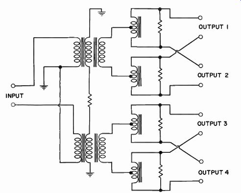
Fig. 5-23. Schematic of a four-set coupler.
Distribution Amplifiers
Where several receivers must be connected to an antenna, the set couplers described previously may not supply sufficient signal. For example, hotels, motels, and apartment buildings often require several outlets. In installations such as these, some amplification must also be provided. This amplification is provided by distribution amplifiers. Essentially, a distribution amplifier is a booster with multiple outlets. The antenna is connected to the distribution amplifier, and the TV receivers are connected to the outlets. In elaborate systems, divider networks may be employed in each leg to provide more outlets. Still more distribution amplifier systems may be inserted in the line to provide still more outlets.
Separate Antenna System
This system (Fig. 5-24) differs from the multiple antenna systems mainly in that a separate antenna is provided for each individual channel to be received. A group of pre-tuned amplifiers, one for each channel, is supplied to provide interference-free signals to each receiver outlet. In addition, individual resistance pads at the input of each channel amplifier are provided to enable the antenna technician to compensate for varying signal levels in any location.
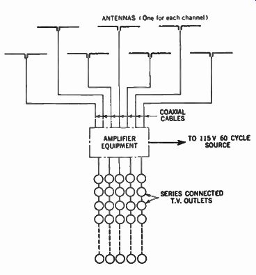
Fig. 5-24. Schematic of a multiple-outlet system with separate antenna for
each channel.
In an installation of this type, it is important to separate the different channel antennas by a distance of 10 ft. or more to prevent any mutual coupling between them that may form a distorted picture. Coaxial cables are used to connect the antennas to the amplifiers in order to prevent noise pickup and match the input impedance of the amplifiers.
Troubleshooting MATV Systems
It is not always necessary to go through an entire troubleshooting procedure to pinpoint MATV troubles. A knowledge of what is a probable system malfunction can often provide helpful shortcuts. The following are the common causes of trouble symptoms in MATV systems.
AC Hum--Hum interference appears as one or two stationary or rolling dark bars on the picture-tube screen. The technician should check with a portable-TV receiver to make sure that the hum isn't originating from a defective filter or circuit fault in the tenant's receiver. Then, if it is found that the hum is originating in the MATV system, it is most likely to be caused by a defective filter in the MATV amplifier.
Picture Rolling--When this symptom appears on one channel only, it is usually caused by sync compression in a single-channel amplifier. (See Fig. 5-25.) As an amplifier ages, tuning shifts can cause an AGC shift to produce increased gain, causing overload. The remedy is to troubleshoot the amplifier.
Cross Modulation in Broadband Systems--When this malfunction occurs, suspect first that signal levels may have been set in the past but the maintenance man or some tenant may have changed the amplifier gain setting.
Ghosts--Sometimes a tenant will attempt to compensate for receiver deterioration by taking more signal out of the MATV system. For example, a tenant might short-circuit the isolation arrangement in the tap-off unit. Although increased signal is obtained, the resulting impedance mismatch often causes ghosts along the trunk line. In some cases, ghosts occur because a tenant has extended the line and added more outlets. Since few tenants understand the principles of impedance matching, ghosts are usually produced as a result.
Snow--If snow is observed throughout the entire MATV system, the amplifier is immediately suspect. On the other hand, snow in a particular branch run is often caused by water entering a splitter or a tap-off unit. However, snow can also be caused by anything from a new building structure to a defective cable, faulty coax connector, or deteriorated TV receiver.
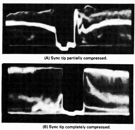
Fig. 5-25. Sync-tip compression due to nonlinear amplification. (A) Sync tip
partially compressed. (B) Sync tip completely compressed.
SUMMARY
The actual selection of the type of antenna to be installed will depend on many factors. The first step in any antenna installation is a survey of the location. Look over the house to note the type of construction, such as brick, stone, frame, etc., and the type of roof. The distance from the transmitting antenna is also an important factor.
Another important decision that must be made in the initial installation is how to support the antenna. Again, one of the primary factors in the determining the selection is the distance from the transmitting antenna. In areas where the signal is strong, any installation can be used; in fringe areas, tall towers are usually necessary.
Guy wires must be attached to practically every antenna installation to support the mast or tower. The only exceptions are self-supporting steel towers, which are set deep in concrete, or eave and roof installations, which extend only a few feet above the roof. In general, separate guy-wire systems should be attached for each 10 ft. in height for masts.
Most television receivers have a 300-ohm input circuit, which must be connected to a 300-ohm antenna system. Failure to observe proper impedance match between antenna and receiver will result in the undesirable effects of noise and interference.
Where interference may be picked up by the antenna lead-in itself, shielded coaxial cable should be used. Since coaxial cable is normally not available with a 300-ohm impedance, impedance matching transformers should be used.
QUIZ
1. What should be the first step to consider when planning an outside antenna system?
2. What determines the type of antenna to use?
3. What determines the type of antenna mast?
4. Can one outside antenna serve more than one TV receiver? If so, how?
5. When should guy wires be used?
6. What is the purpose of the lightning arrester?
7. What is a master antenna system (MATV)? CATV?