All television receivers, irrespective of their location with reference to the transmitting station, require some type of antenna in order to function properly. Television antennas may be classified according to their location as:
1. Built-in antennas
2. Attic or outdoor antennas
3. Master TV antennas, MATV
4. Community TV antenna, or CATV
Built-in antennas, as the name implies, are those which are a component part of the television receiver. A built-in telescopic antenna is included in many receivers, particularly portables. However, in most locations, it will be found that one of the other types of antennas listed will provide better reception. Built-in antennas are usually connected to antenna terminal screws at the rear of the cabinet. If another antenna is used, the built-in antenna must be disconnected from the terminal screws before the new antenna leads are connected in its place. The most common type of indoor antenna is the familiar "rabbit ears." Although it has several different forms, in general, it consists of two arms arranged in a V shape. Both the length of the arms and the angle of the V are usually adjustable.
Attic antennas are designed for mounting in the attics of small dwellings, from which point they are connected to the receiver in the conventional manner. In general, the same types of antennas are used for an attic installation as are used for outdoor installations. Outdoor antennas (Fig. 4-1) are designed for installation on roofs of dwellings or on towers. They are usually supported by a suitable piece of galvanized iron or aluminum piping or mast, the dimensions of which depend upon the height of the antenna array.

Fig. 4-1. TV-antenna arrangement.
Master, community, or cable TV installations are distribution systems rather than a specialized type of antenna. We find that AA quite elaborate antenna arrays are generally used in community systems. This requirement is based on the fact that a community system ordinarily was installed in a "far-fringe" area where the signal level (field strength) is comparatively weak. CATV is now common in cities, suburban, and rural areas. It has increased channel capacity, improved reception of extreme fringe signals, and "imported" signals from "superstations." CATV is considered one of the "new growth" industries in the United States (See Fig. 4-2).

Fig. 4-2. Typical MATV system for an apartment building.
The quality of the picture that is reproduced on the screen of a television receiver is dependent upon many factors, some of which are beyond the control of the receiver. The information presented here is intended mainly to assist the service technician in determining the factor the antenna plays in the normal reception of television.
The strength of the transmitted picture signal that reaches the receiver is a vitally important factor in determining the quality of the picture that is reproduced on the screen. A very weak signal will produce an unsatisfactory picture. In locations where the signal is exceedingly weak, the picture will display a milky appearance, which is usually accompanied by a speckled effect called snow.

Fig. 4-3. Line-of-sight transmission.
TELEVISION TRANSMISSION
The very-high- and ultra-high-frequency waves used for the transmission of television picture signals act quite similar to rays of light. They do not bend around corners and are reflected by obstacles in their path. Therefore, television waves do not follow the curvature of the earth, and reliable reception should be anticipated only in the region determined by the line of sight to the horizon in all directions from the antenna tower of the transmitting station.
The line-of-sight distance, as denoted in television literature, is the maximum distance that high-frequency radio waves will reach without being impeded by the curvature of the earth. It is shown in Fig. 4-3 and is governed by the following relationship: d = 1.41(ht + hr)
where d is the distance between antennas (in miles), ht is the transmitting antenna height (in feet), and hr is the receiving antenna height (in feet). Since signal strength decreases rapidly when the line-of-sight distance is exceeded, it is not possible to reliably predict conditions that might prevail at greater distances away from the transmitter. The technician who installs the television receiver must always carefully check to determine if signals at a particular location are of satisfactory strength.

Fig. 4-4. Direct and reflected signal paths.
The characteristic of high-frequency television signals that permits them to be reflected from the walls of nearby buildings or other objects, under certain conditions, may create multiple transmission paths. Figure 4-4 shows a reflected signal arriving at the receiving antenna a short interval of time later than the signal traveling in a direct path from the transmitter. The effect produced on the picture of the television receiver consists of a multiple image (Fig. 4-5). These multiple images, known as echoes, or ghosts, can usually be prevented by careful installation and orientation of the antenna.
Do not mistakenly believe that the reason for the line-of-sight transmission is due to the television signal. The only reason for the limited distance is the frequencies used for television trans mission. If it were possible to transmit television signals at the low frequencies used by broadcast radio, long distances could also be obtained in television transmission. Of course, this is impossible. As pointed out previously, the entire broadcast band comprises a bandwidth only slightly over one-sixth that of a single television channel.
Actually, television waves do a certain amount of bending as they travel along the earth. Very-high-frequency (VHF) stations can be received beyond the distance computed to be the horizon.
However, at ultra-high frequencies (UHF), the line-of-sight limitations are more pronounced. Also, at UHF frequencies, reflections and ghosts become more of a problem. In fact, a good signal may be received at one point, and just a few feet away no signal will be received because some intervening object has shielded the area. Hence, at UHF frequencies, proper antenna selection and orientation is most important.

Fig. 4-5. Multiple images, known as ghosts, or echoes.
The field strength of a signal is expressed in microvolts per meter (µV/m). The field strength is stated as the voltage developed in a wire 1 meter long at a chosen position in space. If a wire 5 meters long has a voltage of 100 µV induced in it by a certain signal, the field strength of the signal is 20 µV/m. Thus, the microvolts-per-meter unit is a measurement of the actual field strength of an electromagnetic wave. On the other hand, a field- strength meter connected to an arbitrary antenna merely measures the microvolts of signal picked up by the antenna. Field strength is measured with a field-strength meter such as the one shown in Fig. 4-6.

Fig. 4-6. Precision-type, field-strength meter.
TELEVISION DISTRIBUTION SYSTEMS
Since television transmission is limited to line of sight, an efficient relay system is necessary to link a country into television networks. Three principal systems are presently used for this purpose:
1. The underground coaxial cable system
2. The microwave relay system
3. The satellite microwave system
The underground coaxial cable system consists principally of a special type of telephone cable that is capable of passing a wide range of frequencies without the usual prohibitive losses and distortion. For a successful television transmission over longer distances, however, in addition to the coaxial cable, special repeater amplifiers (relay stations) must be spaced at equal distances from one another.
In contrast, the microwave relay system of increasing the range of television coverage consists of a chain of towers located at various distances, which depend on the intervening terrain. Each tower contains a receiver to pick up the signal from the preceding tower and a transmitter to rebroadcast it to the following tower. (See Fig. 4-7.)

Fig. 4-7. Typical microwave-relay tower.
This same principle is employed in transcontinental television broadcasts. In systems such as SATCOM, the signal from the transmitting station is beamed toward the satellite as it orbits the earth. This is still line-of-sight transmission; however, because of the great height of the receiving antenna (on the satellite) the transmitting range is greatly increased.
At the satellite, the signal received from the ground is amplified and sent to the transmitting antenna where it is retransmitted to a receiving antenna on the earth. The signals received are very weak-far too weak for reception by normal receiving equipment. Giant specially constructed antennas are necessary for transmission and reception. These "dishes" are now common sights at television stations and cable TV head-ends. A new industry, referred to as TVRO (television receive only), has developed. The use of satellite antenna by private groups is now economically possible and shows great promise for growth.
The satellite orbits in a geosynchronous pattern above the earth at a height of 22,300 miles above the equator (Fig. 4-8). The satellite appears to be motionless, but in reality it orbits at the same speed as the earth rotates on its axis. Its position in respect to a given point is constantly changing, however. As the earth tilts on its axis, the position of the transmitting and receiving antennas must be able to rotate manually or automatically to keep in step with the satellite's position. Transmissions from a given satellite are possible only when the satellite is in the line-of-sight range from both stations at the same time.
The satellite signals are not in the same frequency band as that transmitted by a television transmitter. The frequency used by the ground transmitter (satellite receiving frequency) is different from the satellite's transmitting frequency (ground-station receiving frequency). These signals fall in the microwave category, or super-high frequencies (SHF). In addition, since different countries have different transmission standards, the signal received from the satellite must be made to conform to the standards in the country where it is being received. Various foreign countries transmit TV signals with more loss lines than the United States. In all cases, the signal received from the satellite must be processed accordingly.
ANTENNA SYSTEM
For the best reception, each antenna should be selected with reference to distance and other factors covering the particular installation. Fundamentally, the three elements present in any television antenna installation are:
1. Antenna
2. Transmission line
3. Receiver
The function of the antenna is to pick up the signal transmitted from the station and to transmit the signal to the receiver through the connecting transmission line.
sea amp

Fig. 4-8. Satellite in a geosynchronous orbit.
Transmission Lines
Two general types of transmission lines act as a transmission link between the antenna and the receiver:
1. The two-wire, parallel-conductor type
2. The coaxial cable type
There are several construction variations in the basic types of transmission lines. In the first type (Fig. 4-9), two parallel conductors are supported a fixed distance apart by means of insulators called spacers. The air forms the dielectric insulation between the conductors.

Fig. 4-9. Flat, parallel, television transmission line.

Fig. 4-10. Tubular television transmission line.
Formerly the most popular two-wire transmission line was parallel-conductor line with standard conductors imbedded in a low-loss insulating material (polyethylene). It had the advantage of low weight, compactness, and neat appearance, together with close and uniform spacing. However, losses were higher in the solid dielectric than in air, and dirt or moisture on the end line tended to change the characteristic impedance. Two-wire trans mission lines of this type are still available in impedances of 300 ohms.
Another type of parallel-conductor twin lead is pictured in Fig. 4-10. This type of twin lead is very similar to that of Fig. 4-9, except that the plastic insulating material is arranged in a tubular fashion and the inside is filled with a low-loss foam material.
Tubular lead exhibits less loss than ordinary flat twin lead.
The most common type of coaxial transmission line consists of either a solid- or stranded-wire inner conductor surrounded by polyethylene dielectric. Aluminum foil and stranding is wrapped or copper braid is woven over the dielectric to form the outer conductor, and a waterproof vinyl covering is placed on top of the braid. This cable is made in a number of different diameters.
It is moderately flexible and so is easy to install. Coaxial cable is available in characteristic impedances of 75 ohms. (See Fig. 4-11.)

Fig. 4-11. Coax television transmission cable.
Receivers
Most television receivers are manufactured with an input impedance of 300 ohms. Thus, if a coaxial transmission line is used, some means must be provided to match the lower impedance of the transmission line of 75 ohms to the 300-ohm impedance of the receiver. A special device, called an impedance matching transformer, or balun, is employed between the transmission line and the receiver antenna terminals.
Another example of an impedance-matching arrangement is found in the connection of two television receivers to the same 75-ohm line. In this case, a splitter is generally used, both to provide correct impedance matching and to isolate the two receivers from each other. In other words, unless a suitable degree of isolation is provided, the radiation from one receiver could produce interference in the picture displayed by the other receiver.
PRACTICAL ANTENNA CALCULATIONS
For proper antenna design, it is necessary to know the length of the electromagnetic waves involved. In order to determine wave lengths, it is necessary to know the speed and frequency at which electromagnetic waves travel through free space. In speaking of the frequency of electromagnetic waves, we mean merely the number of waves passing a given point in 1 second, expressed in megahertz [millions of hertz (MHz)].
Since electromagnetic waves of all lengths move at the same speed, the number of waves passing a given point in 1 second will be small if the waves are long and large if the waves are short.
Thus, 500,000 waves that are 600 meters in length will pass a given point in 1 second at a frequency of 500,000 hertz. Similarly, if the waves were only 1 meter in length, 300,000,000 would pass each second at a frequency of 300 MHz. For all practical purposes, the actual velocity of electromagnetic waves is 300,000,000 meters or 984,300,000 ft/sec.
Now, if the speed at which the waves travel is equal to 3 X 10' m/sec, the distance it will cover in one cycle will be equal to this velocity divided by the frequency in hertz per second, or: 3 X - x 10' where X (the Greek letter lambda) is the wavelength (in meters), and f is the frequency (in hertz per second). Since feet and inches are the measurements most commonly used in the United States, the preceding formula can be converted to:
À = 984 where X is the wavelength (in feet), and f is the frequency (in megahertz), and - 11,808 X where X is the wavelength (in inches), and f is the frequency (in megahertz). The values obtained in the foregoing equations are only approximate; however, they are accurate enough for all practical applications.
The length of a dipole antenna is one-half wavelength. Each dipole antenna consists of two elements, each a quarter-wave length long, as shown in Fig. 4-12. Thus,
x 2,952 7 f
where X/4 is the length of a quarter-wavelength (in inches), and f is the frequency (in megahertz).

Fig. 4-12. Relationship between wavelength of received signal and length of
dipole element.
Due to the electrical characteristics of the antenna material, it has been found that the antenna elements should be somewhat shorter (about 5 percent) than that given in the preceding formula. The formula then becomes
x - 2,952 x 0.95 4 f 2,804 in.
f
From this last formula it is comparatively simple to obtain the antenna dimensions for each frequency by substituting the proper value in megahertz.
Dipole antennas that are to be used in outside installations usually consist of two quarter-wavelength sections of 3/8 -in. tubing or rod. The following example shows the general procedure when it is desired to calculate the exact length in inches of each element (quarter-wavelength) of a simple half-wave-dipole antenna.
Example-It is desired to determine the length of a quarter wave-dipole rod suitable for use on channel 4, where the frequency has an average value of 69 MHz. What is the dipole-rod length?
Solution-By employing the preceding formula, substitution of values gives the quarter-wavelength in inches:
_ 2,804 7 69
= 40 (approx.)
Using a similar procedure, it is comparatively simple matter to calculate antenna dimensions for any desired channel or frequency..
DIPOLE ANTENNAS
The fundamental form of a dipole antenna consists of two single wires, rods, or tubes, with combined lengths approximately equal to half the transmitting wavelength. It is from this basic unit that various forms of television antennas are constructed. It is also variously known as a half-wave dipole, half wave doublet, or hertz antenna.
The dipole elements are made of steel-, aluminum-, or copper alloy tubing and are surface-treated against corrosion. The receiver dipole is equipped with terminals at its adjacent ends for transmission-line connections and must be properly insulated from the mast or supporting structure. The element is then connected to the receiver via the transmission line (Fig. 4-13). Actually the simple dipole antenna (Fig. 4-14) is seldom used in modern television systems, although it is the basis for practically all television antennas. For this reason, it has been included in our discussion of antennas.

Fig. 4-13. Transmission line connected between half-wave dipole and receiver.

Fig. 4-14. Mounting arrangement and connection of half-wave dipole and transmission
line.
Folded Dipoles
The necessity for separating, insulating, and mounting the receiver dipole at its center tends to weaken and complicate the antenna assembly. Because of this, a considerable simplification may be obtained by employing an unbroken member bent as shown in Fig. 4-15. A television antenna of this type is known as the folded-dipole type and is widely used. The spacing between the folded dipole elements should vary inversely with the frequency; that is, the higher the frequency, the smaller the spacing.
The element spacing for the center frequency on the low band is usually 2 to 3 in., and 1 to 2 in. for the high band.
One of the first requirements for television reception is that the antenna system should be flatly tuned; that is, it should respond fairly evenly over the waveband involved and also pick up the FM sound transmissions. This compromise is often assisted by choosing the length of the antenna to resonate at a frequency that is intermediate between sound and video transmission.
The polarization of the signal waves to be received may be either vertical or horizontal. An antenna placed in the horizontal plane radiates horizontally polarized signals, whereas an antenna placed in a vertical plane radiates vertically polarized signals. To obtain maximum energy transfer, the receiving antenna should be polarized in the same manner as the transmitting antenna. In the United States, horizontal polarization is used at the transmitter; hence it should also be employed at the receiver. Horizontal polarization means that the dipole element should be placed in the horizontal plane, that is, parallel with the ground. (See Fig. 4-16.)

Fig. 4-15. Dimensions of a folded-dipole antenna.

Fig. 4-16. Magnetic and electric fields of horizontally polarized signal waves.
In England, vertical polarization is employed; hence the dipole should be placed perpendicular to the ground or standing on end by American standards. Either method will work. The important factor is that both transmitting and receiving antennas should be placed the same.
PARASITIC ELEMENTS
A parasitic element, as employed in television antennas, is a dipole slightly too long or too short for exact resonance at the desired frequency. It is mounted at some fraction of a wave length before or behind the driven element (dipole). Parasitic elements are not cut at the centerpoint and are not connected to the transmission line. The centerpoint of the element is electrically neutral and can be grounded. This is convenient for lightning protection because it permits making the entire antenna structure of conductive tubing, such as aluminum, and grounding the central supporting mast at the base.
Current induced in a parasitic element by the advancing wave front produces a local field about it that is coupled to the driven element because of the physical closeness. Spacing and tuning of parasitic elements are adjusted so that the currents produced in them by the received signal produce fields that add in correct phase to reinforce the field of the received signal at the driven element. For signals from the opposite direction, the action is exactly reversed; and the signal is substantially canceled in the driven element.
Director and Reflector Elements
A director element is about 4 percent shorter than the driven element for average element spacing and is mounted in front of the driven element on the horizontal support member, which holds all the elements in proper relationship. The spacing between the director and driven elements can vary from about 0.08 to about 0.15 wavelength in practical antennas. Closer spacing will increase the front-to-back ratio but makes the array tune more sharply, which is a disadvantage when many widely separated television channels must be received on a single antenna.
Wider spacing helps broaden the tuning of the array but lowers the front-to-back ratio.
A reflector element is about 5 percent longer than the driven element at usual spacing and is mounted on the supporting bar behind the driven element, as shown in Fig. 4-17. While the spacing between the elements is shown as 0.25 wavelength in Fig. 4-17, it will vary from about 0.10 to 0.25 wavelength in an actual antenna. The effects of changing the spacing are quite similar to those produced by similar changes in the director length.

Fig. 4-17. Location and effect of the reflector element on signal reception.
The effect of the reflector is critically dependent upon the spacing between reflector and dipole. When the spacing is a quarter-wavelength, radiation from the reflector will exactly reinforce that from the dipole in a forward direction. This effect is most easily explained when the dipole is considered as a transmitting antenna, as follows: Radiation from the dipole travels both forward and backward; in the latter direction, it reaches the reflector and induces a current in it. Since the radiation has traveled a quarter-wavelength on its way to the reflector, it will be 90° lagging in phase relation to the dipole where it originated. A current of this phase lag is therefore set up in the reflector, which, in turn, reradiates the signal.
By the time this secondary radiation has returned to the dipole, it is an additional 90° late in phase, making a total phase lag of 180°. However, the oscillations in the dipole will have progressed through a half-cycle during this half-wave time interval and will be 180° ahead of the initial condition when the radiation left on its way to the reflector. In other words, the radiation from the dipole will be a half-cycle ahead of the reference point, while that returning from the reflector will be a half-cycle late, bringing the two to the same point in the period of an oscillation.
Being in identical phase, the radiations from the dipole and reflector reinforce each other in the forward direction. The reverse is true for signals from the backward direction, that is, from the direction of the reflector. Here the two signals cancel. If the current induced into a reflector is as great as that flowing in the dipole, each would produce the same radiated field strength.
The forward radiation would therefore be doubled, while that to the rear would be exactly canceled, giving zero backward radiation.
The problem of radiation and absorption (transmission and reception) by an antenna system is strictly reversible in all ordinary conditions. Whether the antenna is regarded as a transmitter or receiver, these directional effects will be exactly similar, provided, of course, that the waves arrive in the plane in which the dipole and reflector are situated.
In practice, the resistance of a reflector will never be zero; and while the current in it can be made equal to that of the radiator if both are connected to a feeder, the current in a parasitic reflector must always be less than that in the dipole that gave rise to it.
Therefore the forward radiation is never exactly doubled, and the backward radiation is never fully cancelled.
ANTENNA DIRECTIVITY PATTERN
The horizontal antenna dipole is inherently directional, being most effective to signals arriving in the broadside direction and least effective to those arriving from a parallel direction. This effect is usually represented in the form of a polar diagram, or directivity pattern, in which the radius of the curve from the center of the antenna elements represents the relative response in any given direction.
The function of an antenna pattern is primarily to enable the service technician to evaluate the efficiency of an antenna and assist in the proper orientation on the site of installation. Designing and plotting an antenna pattern is generally performed by antenna manufacturers, but plotting may be accomplished as follows: A minimum usable value of signal strength is chosen on the basis of what the average television receiver will require for satisfactory reception. Determine all the points in the area surrounding the antenna where exactly this value of field strength is found and plot by bearing from true North (or some other convenient reference direction) and distance in miles (or some other desired linear unit. With a sufficient number of points plotted, a continuous smoothly curving line is drawn joining them all; one may be reasonably certain that all the area enclosed by this curve will provide at least the minimum required signal.
In practical service work, directivity patterns are always plot ted in terms of voltage gain because this unit is most convenient to use in connection with the field-strength meter, which is usually a part of the television service technician's equipment.
Antenna receiving patterns are usually made by rotating the antenna about its vertical axis and plotting values of voltage gain radially outward from the center of each change of angle.
The complexity of an antenna has a direct bearing on its efficiency as well as its directional effects. Roughly, the voltage developed in the antenna is proportional to the combined lengths of the elements multiplied by the field strength of the signal. This length is measured in units of half-wavelengths. A reduction in the voltage realized at the antenna terminals results from the mutual coupling of the elements.
A comparison of the theoretical efficiency of various types of antennas are as follows:
Elements Types Voltage Gain
1 Simple dipole 1.0
2 Dipole and reflector 1.6
4 2-Bays 2.3
6 3-Bays 2.8
8 4-Bays 3.2
The reference value of 1.0 shown for a simple dipole is the universal standard of comparison. This reference dipole is cut to a half-wavelength for each channel measured.
As previously noted, the voltage developed by a half wavelength antenna is proportional to the length of the antenna.
Therefore, for purposes of additional elements, multiples of half wavelengths are used.
The receiving antenna height, particularly in fringe areas, is an important factor in its efficiency, or signal capture, as shown in Fig. 4-18. The possibility of interference is shown by the irregularity of the curve representing signals in the high-channel group.
This particular effect, however, is not predictable and can be determined only by proper orientation.
The field pattern (directional-response pattern) of a typical dipole antenna is shown in Fig. 4-19. For sake of simplicity, the directions are given as North, South, East, and West in both the schematic antenna and the polar diagram. From this diagram, it will readily be observed that the maximum signal strength is obtained when the antenna is broadside to the transmitter. Similarly, the signal capture is not critical through the angle of rotation over which the antenna can be moved before losing more than half of its effectiveness. In Fig. 4-19 the concentric circles represent the voltage gain, where unity, or 1.0, is taken as reference for all comparisons.
If a reflector is added to the dipole, the gain and directional characteristics of the antenna are changed and the polar diagram will take the form indicated in Fig. 4-20. It will be observed from the diagram that the angle is still sufficiently wide, generally at least 80°.
So far, we have considered an antenna operating only on the channel for which it was designed. It is the usual practice to use dimensions that give half-wave dipoles in the middle of the low channels. When used on the high channels, a third harmonic will result, giving the antenna pattern shown in Fig. 4-21.
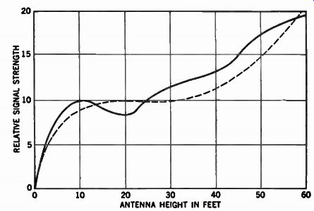
Fig. 4-18. Relative signal strength at antenna per height in feet (applies
only at considerable distance from transmitter).
A dipole operated in this way will have six lobes and will be symmetrical and oriented as indicated. With reference to the field pattern, these lobes are too narrow and point in different directions from that previously shown. This will make orientation difficult or even impossible if the stations on the high- and low band channels are in the same direction. It follows that no reliable antenna manufacturer would sell an antenna with these characteristics without showing the relation of the lobes for each frequency.

Fig. 4-19. Directional response of a dipole antenna. (A) Antenna. B) Polar
response.

Fig. 4-20. Directional-response pattern of a folded-dipole antenna with reflector.
(A) Antenna. (B) Polar response.

Fig. 4-21. Directional-response pattern at a frequency other than the one
the antenna is cut for. (A) Antenna. (B) Polar response.
The ratio between maximum and minimum voltage (measured with a voltmeter slid along the transmission line) is called the voltage standing-wave ratio (VSWR). It is obtained numerically by dividing the maximum voltage by the minimum voltage; thus maximum and minimum values of 15 and 5 would mean a SWR of 3.
If the SWR is plotted on a logarithmic scale against percent loss, the curve will take the form shown in Fig. 4-22. Here it will be observed that a SWR of 2 will cause a loss of only 10 percent, while a SWR of 3 will cause a loss of 25 percent.
ANTENNA IMPEDANCE MATCHING
Impedance matching is a very important factor in antenna installations. When the receiver input matches the impedance of the transmission line, the transmitted signal is completely absorbed; as a result, there are no reflections or standing waves on the transmission line and consequently no ghost images. It should be observed that the antenna impedance is important only from the standpoint of power transfer. It is only when the antenna impedance matches that of the transmission line that maximum power transfer takes place. A condition that may easily arise is the mismatch of 300 ohms to 75 ohms; this produces an SWR of 4 and a loss of 37 percent.

Fig. 4-22. Relationship between voltage SWR and percent of loss due to mismatch.
A method of matching impedance employs a commercial device called a balun (from "balanced-unbalanced"). A balun consists of two coils, each of which can be considered as a trans mission line having a surge impedance of 150 ohms and a length of approximately one-quarter wave at the lowest operation frequency. The two transmission lines, or coils, are connected in parallel on one end, forming the 75-ohm impedance, and in series on the other end, producing the 300-ohm impedance.
A transmission-line coil and equivalent diagram are shown in Fig. 4-23. The transmission line T, having a surge impedance of 150 ohms, is wound on the coil for F. The magnetic fields produced by the symmetrical, or push-pull, current neutralize each other to the closely spaced conductors of the transmission line.
The magnetic fields produced by the unsymmetrical, or push-push, current are added together and would pass through the transmission line if it were not wrapped to form a coil.

Fig. 4-23. Transmission-line coil and equivalent diagram for a balun. (A)
Transmission lines. (B) Equivalent diagram.
The mutual inductance between the individual turns of the coil acts like a conventional choke coil B, which offers a high impedance to the push-push currents. The transmission-line coil there fore acts as an ideal transformer, which passes the push-pull currents and eliminates the push-push currents.
YAGI ANTENNAS

Fig. 4-24. Two commercial Yagi antennas.

Fig. 4-25. Response pattern of a Yagi antenna to signal from three different
angles.
Generally, there is no benefit to be gained by adding additional reflectors. However, additional directors can be added. When more than one director is used with the folded dipole and reflector, the antenna is called a Yagi (named after Hidetsugu Yaga, the Japanese physicist who discovered it). Two types of Yagi antennas are shown in Fig. 4-24.
The Yagi antenna provides a very high gain. However, its principle disadvantage is that it is highly directive (see Fig. 4-25) and covers a very narrow band of frequencies. Both of these factors and its high gain make it highly desirable for fringe-area use. As more directors are added, the gain is increased; but the band width is narrowed, and the directivity pattern becomes sharper.
For VHF applications, Yagi antennas with up to 10 elements are employed; for UHF applications, even more elements may be used.
Optimum operation at VHF frequencies can be obtained for only one channel with a Yagi antenna; however, satisfactory operation may be obtained for two, three, or even more adjacent channels. For UHF operation, several adjacent channels can usually be received from a single Yagi antenna. For even greater gain, two Yagi antennas can be stacked one above the other.
CORNER-REFLECTOR ANTENNA
The parabolic-reflector type of UHF antenna has found increased use in weak-signal areas. A more familiar application of the parabolic-reflector principle is found as a well-known part of many light fixtures, where it is employed for concentration of light beams. This useful property, when utilized for concentration of UHF television signals, has provided several antennas of various design for both transmission and reception.
Because of the somewhat difficult design principles involved in the construction of a parabolic antenna, tests have shown that, instead of using curved surfaces, it is possible to use two flat surfaces that are placed so as to intersect each other at some suitable angle, forming a corner. An antenna of this type, known as the comer reflector, is shown in Fig. 4-26.

Fig. 4-26. UHF corner-reflector antenna.
The reflector grids have an included angle of 90° and are made from hard aluminum tubes; other materials, such as wire fencing, can be used if desired, providing the wire spacing is small in comparison to a wavelength. The driven element, usually a dipole antenna, is placed at the center of this corner angle and at some distance from the vertex of the angle. The elements are supported near their centers with ceramic insulators in order to minimize the effect of rain, snow, and ice.
The response pattern of the antenna depends not only on the corner angle, but also on the distance between the antenna and the vertex of the reflector corner. When this distance is large, that is, in comparison to the wavelength used, a pattern containing more than one main lobe is obtained, as shown in Fig. 4-27.
Moving the antenna too close will affect the vertical response of the array and make it more susceptible to ground-reflected signals. Since neither of the foregoing conditions is desirable, the exact positioning of the dipole must be obtained.
(A) Spacing too small (B) Spacing too great

Fig. 4-27. Effect of spacing between
dipole elements and reflector on directivity.
The corner angle of a commercial array is 90°. A similar bend is included in the dipole element. The reflector-bar spacing must be controlled within one-fifth of a wavelength at the highest frequency at which the corner-reflector antenna is to be used.
ANTENNA SELECTION
The selection of the proper antenna for a given location is dependent on many factors. Perhaps the primary concerns are the distance from the station and the signal strength available. In metropolitan areas, satisfactory reception of VHF and UHF signals can usually be obtained from a built-in, or indoor, antenna. However, a more elaborate antenna system is usually required for color reception than is needed for black-and-white reception.
As the distance from the transmitter to the receiver increases, antennas with more gain are necessary.
Another consideration in selecting the proper antenna is the number of channels available. For example, if both VHF and UHF channels are available, an antenna suitable for both bands should be used if sufficient signal strength can be obtained with it. For fringe areas, all-channel Yagis are available. However, in extreme fringe areas, an antenna cut for the channel desired must usually be employed. Sometimes antennas must be stacked to obtain sufficient signal strength. Also, it may be necessary to use separate antennas for each channel.
ANTENNA TROUBLESHOOTING
The most common symptom of trouble produced by an antenna is weak, snowy, or no picture reproduction on some or all channels. Note that sound is often satisfactory even when the picture is very weak or absent. This occurs because the sound signal has a comparatively high level, and the receiver provides high gain in the sound channel. Inspection of the antenna might show, for example, that one or both of the lead-in conductors have broken loose from the antenna or that the lead-in has become damaged at some point. Lightning damage can melt a lead-in conductor, usually at a point where the stroke arcs to grounded objects. Although lead-in that is not connected to the antenna will pick up more or less signal, its response is unpredictable. In most cases, all channels are weakened, but in exceptional cases most channels might be weakened, with stronger reception on one or two channels.
If a folded-dipole construction or the equivalent is used in the antenna, the system can be checked for continuity with an ohm meter. However, the ohmmeter will not read 300 ohms; only the de resistance of the conductive path is indicated. An infinite reading shows that there is an open circuit; a very high resistance reading shows that there is a poor connection.
Sometimes an antenna system becomes intermittent, and the picture varies erratically from time to time. In most cases, the symptom is most annoying in windy weather. Intermittents are the most difficult faults to locate, and sometimes it is most expedient to simply replace the lead-in (and the antenna, also, if it is in badly deteriorated condition). It is good practice to install the lead-in securely so that it does not whip or swing in the wind. Not only will this precaution stabilize picture reproduction on the high frequencies, but it will also prevent metal crystallization and eventual failure.
SUMMARY
There are basically four classes, or types, of television antennas. They consist of built-in antennas for primary areas to out door antennas for far-fringe areas of 75 miles and over. The quality of the picture that is reproduced on the screen of a television receiver is dependent on many factors, but the antenna plays a very important part in normal television reception.
The transmission of a television picture signal acts quite similarly to rays of light; the signal will not bend around corners and is not reflected by obstacles in its paths. Therefore, television waves do not follow the curvature of the earth, and reliable reception should be anticipated only in the region determined by the line of sight to the horizon in all directions from the antenna tower of the transmitting station.
The United States uses a positive transmission signal. Various foreign countries transmit TV signals with more lines than the United States in some instances and fewer lines in other instances.
Impedance matching of the antenna is a very important factor.
When the receiver input matches the impedance of the transmission line, the transmitted signal is completely absorbed; and as a result, there are no reflections, or standing waves, on the trans mission line and consequently no ghost. A condition that may easily arise is the mismatch of 300 to 75 ohms. This condition will exist when a 300-ohm antenna is connected to a receiver having a 75-ohm input impedance.
QUIZ
1. Name the four classes of television antennas.
2. What are echoes or ghosts?
3. Explain the purpose of the transcontinental television transmission system.
4. What are the three factors covering antenna installations?
5. What are the two general types of transmission lines?
6. What are parasitic elements?
7. What is a reflector? A director?
8. Why are VHF stations easier to receive than UHF?
===