After all the necessary adjustments have been made, the picture may have certain defects altogether different from those described in Section 6. A multitude of patterns may be superimposed upon the normal picture. These patterns are produced by man-made disturbances usually termed interference.
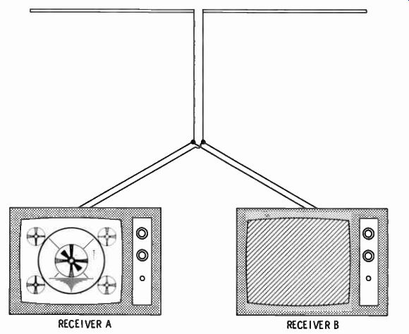
Fig. 7-1. Two receivers operated directly from the same antenna, which can
result in mutual interference.
As an illustration, when two receivers are operated directly from the same antenna, it may happen that mutual interference occurs, as shown in Fig. 7-1. This type of interference is caused by front-end radiation, and the reception on both receivers will usually be substantially normal on certain channels. On other channels, it can happen that receiver A interferes with receiver B; while on still other channels, receiver B interferes with receiver A. The cure for this trouble is to use a two-set coupler that provides ample isolation between the receivers.
As evidenced in radio-broadcast reception, interference is recognized by a burst of noise or continuous background noise. In television reception, interference is evidenced by a burst of light upon the picture screen, momentary "tear out" of the picture, formation of various patterns on the screen, or small spots of light in the picture. Fig. 7-2 shows the appearance of "snow" on a picture-tube screen.
Since television receivers are designed to operate at much higher frequencies than broadcast-band radio receivers, the sources of interference are not the same for the two types of receivers. A television receiver is almost immune to weather produced interference, which is most common in radio reception.
Some forms of interference are easily identified by an analysis of the interference patterns formed on the screen. After they are identified, corrective measures can be applied to eliminate them.
Other types of interference, however, are not so easily identified; and, in some cases, there are no known corrective measures.
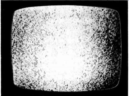
Fig. 7-2. "Snow"' pattern on picture-tube screen.
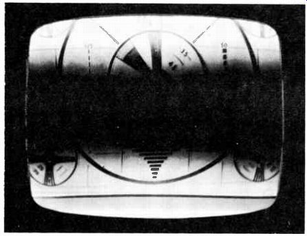
Fig. 7-3. Appearance of 60-hertz hum bar in the picture.
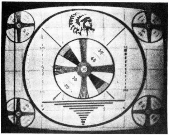
Fig. 7-4. Barkhausen oscillation.
It is of paramount importance, therefore, that every service technician be thoroughly acquainted with the various forms of interference affecting television reception and know how to identify each type. Proper identification may mean success or failure in correcting the trouble because if there is no clue as to what is causing a particular type of interference, no corrective measure can be applied to it. Figure 7-3 shows the appearance of a 60-hertz hum bar in the picture.
To anticipate subsequent discussion, it will be observed that interference may be either external or internal. In other words, if one receiver is interfered with by another receiver, the source of interference is external. On the other hand, a snow pattern exemplifies internal interference; receiver circuit noise is the source of the snow in most cases. Again, if a 60-hertz hum bar appears in the picture, the source of the interference is usually internal.
Another example is shown in Fig. 7-4, where Barkhausen oscillation produces the vertical black line at the left of the screen. The source of this type of interference is in the horizontal-output stage of the receiver.
COMMON TYPES OF INTERFERENCE
Television receivers are greatly affected by man-made noise arising from various types of electrical apparatus. Some types of interference frequently encountered by television service technicians are listed below. (They are not necessarily listed in order of their importance or frequency of occurrence.)
1. Ignition or spark
2. Diathermy
3. Germicidal-lamp radiation
4. 4.5-MHz sound-beat pattern
5. Police, amateur, and other stations
6. Two or more non-synchronized TV carriers on same channel
7. FM transmitter heterodyning with local oscillator in receiver
8. Radiation from local oscillator in a neighboring FM or TV receiver
9. Oscillation in video IF amplifier
10. Barkhausen oscillation from the horizontal-deflection generator
11. Reflections or ghosts Ignition Interference
Ignition interference from trucks, automobiles, and aircraft may be identified by streaks and splashes on the picture. The ignition system of trucks will produce the most intense interference pattern. It usually consists of a series of broken horizontal dark lines, as shown in Fig. 7-5, the number or spacing of which depends on the frequency of the offending spark.
Aircraft in the vicinity may also produce interference that is usually identified by a temporarily fluctuating picture, usually lasting only a few seconds. Since the noise from the aircraft is usually heard at the time the fluctuation of the picture occurs, identification of this type of interference is comparatively easy.
Interference of this same type can occur from high-voltage and corona discharge in the high-voltage supply of the receiver, as well as in high-tension lines near the receiver location. In addition, electric motors, doorbells, buzzers, and signaling systems, such as teletype machines, usually generate an interference pat tern similar to that made by ignition systems.
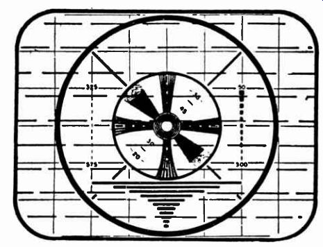
Fig. 7-5. Test pattern showing effect of automobile ignition interference.
Corrective Measures--At the outset, it should be emphasized that there is no clear-cut method whereby all interference problems due to ignition or other causes may be solved. About the only corrective measure with respect to ignition interference is to ascertain that a good antenna is used, that is, one that will result in the best possible pickup of the signal.
At the time of installation, checks should be made to determine the type of interference, if any, which is present at the particular location. The antenna should then be located as far as possible from the suspected source of interference. For example, if the receiver is located near a heavily traveled arterial highway or street intersection, the antenna should always be installed as far from the traffic as possible, and the twin-lead twisted once every 5 ft. After this has been accomplished, an effort should be made to eliminate the remainder of the interference by manipulating the antenna, perhaps by increasing the antenna height by several feet.
In locations plagued by interference, shielded twin-conductor cable or coaxial transmission lines should be used. The use of the shield will prevent most of the noise pulses from reaching the transmission line. For a shielded line to be completely effective, however, the shield must be properly grounded.
In cases where a coaxial cable (single conductor) is used, be sure proper impedance-matching devices are used; otherwise, the problems produced by the mismatch may be greater than those of the original problem. Figure 7-6 illustrates the appearance of RF interference in the picture.
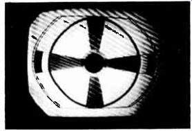
Fig. 7-6. Appearance of RF interference in the picture.
Diathermy
Diathermy interference (Fig. 7-7) is caused by unshielded medical diathermy machines and x-ray equipment. It manifests itself in a herringbone pattern or one of two dark bars moving slowly up and down the picture. If the disturbance is extremely strong, the interference pattern will remain stationary while the picture floats in the background.
Many diathermy machines consist of oscillators using raw 60 hertz ac on the plates. Distribution of the pattern relative to picture height is usually similar to a 60-hertz hum bar due to the strong ac ripple in the signal. This "strip," or bar, pattern will vary in position relative to the top and bottom of the picture, depending on the phase relation between the power lines supplying the diathermy machine and the vertical scanning frequency of the receiver.
Sometimes if this bar happens to be so phased as to occur near the vertical-blanking interval, it will show up as two split narrow "strips"--one at the top of the picture and one at the bottom. The fine-line pattern within the "strip" will vary in spacing, depending on the frequency of the diathermy oscillator; and, as these oscillators are not crystal-controlled, the fine-line pattern will usually vary, assuming various positions between horizontal and vertical.
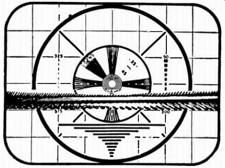
Fig. 7-7. Test-pattern showing effect of diathermy interference.
Corrective Measures--In the case of diathermy interference, corrective measures are practically nonexistent since the signal from a diathermy "transmitter" behaves very much the same as television signals; that is, it is picked up by the receiver antenna.
It is evident that the only permanent remedy against television interference of this sort is to incorporate preventive measures at the source, that is, by proper shielding and filtering of the diathermy machines, by shielding of the room(s) in which they are operated, or both. Fortunately, modern diathermy machines now operate on different frequencies and do not produce the interference previously encountered.
4.5-MHz Sound-Beat Pattern
A 4.5-MHz sound-beat pattern may be recognized by a stationary, very fine herringbone pattern independent of sound modulation and extending over the whole picture. This is caused by the intercarrier sound-IF signal being coupled to the picture tube and heterodyning between the sound and video-IF carriers.
Figure 7-8 shows a 4.5-MHz beat pattern.
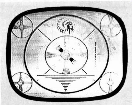
Fig. 7-8. 4.5-MHz beat pattern.
Corrective Measures--Most receivers employ a fairly high-Q trap, tuned to 4.5 MHz and installed either in series with the cathode-ray-tube grid or in the video-amplifier chain somewhere between the point of sound takeoff and the cathode-ray-tube grid. This trap may need readjustment. In extreme cases, it may be necessary to install an additional trap at some other point in the circuit.
Police, Amateur, and Other Stations
Interference from police, amateur, and other stations usually emanates from transmitters being located in close proximity to television receivers, with the result that a high-signal level is fed into the receiver circuit. The fact should not be overlooked that most video amplifiers will amplify to approximately 4 MHz and consequently will readily amplify the signal from a broadcast station if the receiver happens to be in the high-signal area very close to the transmitter. Figure 7-9 shows a 28-MHz beat produced by an amateur transmitter.
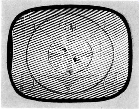
Fig. 7-9. 28-MHz beat produced by amateur transmitter.
Corrective Measures--Corrective measures consist of judicious use of shielding of the affected parts of the receiver and the use of traps tuned to the frequency of the offending transmitter.
Two or More Non-synchronized TV Carriers on Same Channel
Interference resulting from two or more non-synchronized TV carriers on the same channel usually affects reception in fringe areas where the television receiver is located equidistant between two or more stations. Sometimes the signals from the different stations are almost equal in strength, and as a consequence the receiver cannot discriminate between the transmitters. This type of interference is called the windshield-wiper picture symptom if the receiver locks on one TV signal while the blanking bars of the other signals "wipe" across the screen (Fig. 7-10). But the interference is called the venetian-blind picture symptom if the beat frequency between the two signals produces visible horizontal bars on the screen (Fig. 7-11). Fig. 7-10. Windshield-wiper effect.
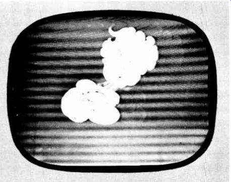
Fig. 7-11. Co-channel interference.
Corrective Measures--The only possible solution to interference problems of this sort is to employ a highly directional antenna and mount it in a rotating mechanism so that it can be precisely aimed at the desired station.
FM Transmitter Heterodyning with Local Oscillator
The heterodyning of an FM transmitter with the local oscillator and the resulting beat coming in on the lower television channels is another cause of interference. Receivers in most of the larger television areas where powerful FM transmitters are located are usually affected by this type of interference.
It is usually recognized on the screen as an ever-changing pat tern of parallel lines sometimes assuming a herringbone characteristic. The pattern will usually change continuously, except when the FM transmitter modulation is off; and the movement of the lines in the pattern will not bear any relation to the accompanying television sound. The number of lines or bars varies according to the modulation of the interfering transmitter.
Corrective Measures--An effective corrective measure in this case consists of fairly high-Q traps at the antenna input to the RF unit of the receiver and tuned to the interfering FM signal.
Radiation from the Local Oscillator in a Neighboring FM or TV Receiver
Interference emanating radiation from a local oscillator in a neighboring FM or TV receiver will vary, depending upon what channel the interfering receiver happens to be tuned to and the nature of the signal it heterodynes with. It will usually result in a fine herringbone pattern, covering the entire picture, although sometimes it will take the form of a ghost picture that seems to float around in the background of a picture tuned in on one of the TV channels.
This trouble is commonly encountered when two or more TV receivers are operated from the same antenna without isolating couplers connected into the lead-in system. It also occurs when individual antennas are used with two or more receivers and the lead-ins are run close together. Even if the lead-ins are well separated, interference sometimes occurs when the antennas are mounted too closely together on the same roof. Figure 7-12 shows the appearance of local oscillator interference.
Corrective Measures--The solution is to install a wave trap tuned to the interfering frequency.
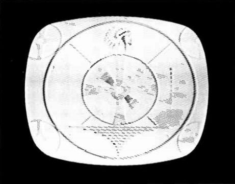
Fig. 7-12. Effect of local-oscillator interference from another TV receiver.
Oscillation in Video IF Amplifier
Interference caused by oscillation in the video IF amplifier will usually be manifested as a pattern of lines that are approximately 3/32 in. apart. This pattern will be noticed on all channels and usually only when the contrast control is advanced near or past the midpoint of its travel. This interference can usually be traced to an open-screen bypass capacitor in one of the video IF amplifier stages; or, in receivers employing stagger-tuned IFs, oscillation can result if several of the stages are peaked too closely together.
Note that the picture symptom can vary considerably, depending on the amount of IF feedback and the incoming signal level.
For example, strong signal may be reproduced at low contrast and with ringing of vertical lines with certain spacing, as shown in Fig. 7-13. At a reduced signal level, a negative or partially negative picture may appear. Again, at a slow signal level, the screen becomes blank due to increased IF feedback at low AGC voltages.
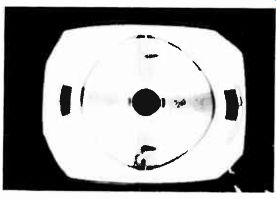
Fig. 7-13. Distorted reproduction with wedge ringing at about 2.5 MHz.
Barkhausen Oscillation
Barkhausen interference originates in the receiver's horizontal deflection circuit. It will show up as a dark vertical line or series of lines at either side of the picture. If a pattern such as the one described is noticed, a permanent magnet held close to the out side of the horizontal-output tube will have a noticeable effect on the pattern.
Barkhausen effect is a type of high-frequency oscillation that takes place within the electron stream in the tube. The frequency is determined by the distance between the elements and by the velocity of the electrons. It is independent of external tuning circuits.
Corrective Measures--Replacement of the horizontal deflection tube will usually clear this type of interference. Attaching an ion-trap magnet to the outside of the horizontal-output tube will also usually eliminate Barkhausen oscillations.
Reflections, or Ghosts
Perhaps one of the most prevalent forms of interference is due to reflections of the signal, generally termed ghosts (Fig. 7-14).
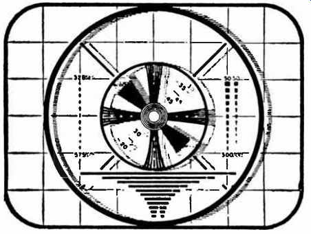
Fig. 7-14. Test pattern showing effect of multiple images, or ghosts.
Since there are numerous forms of this type of interference, they will be treated according to their appearance on the screen.
Trailing Ghost--Probably the most common type of ghost is the trailing ghost, which is usually due to a reflection from a building, hill, or other structure that reflects the television signal from the transmitter. This reflected signal, or "echo," which is usually weaker than the direct signal, arrives at the receiving antenna later than the direct signal, and the ghost, or echo, will appear on the right hand, or trailing edge, of the picture.
Sometimes there are locations where several reflected signals from different buildings or structures reach the receiver, resulting in several ghost images in the picture. These are called multiple ghosts. Ghost images can be positive or negative, depending on the relative phase of the direct and reflected signal. The relative phase depends on the location of the antenna. If it is located some distance from the transmitter, the relative phase changes, and the direct and reflected signals either aid or oppose, producing a positive or negative ghost. A negative ghost is one where the image is reversed; that is, the white portions are black, and the black portions are white.
Corrective Measures--Where the reflected signal is arriving at the receiver from the rear, a reflector on the antenna will be helpful because it will minimize the rear pickup of the antenna to some extent. If the reflected signal is arriving at the receiver from one side, it can be minimized by orienting the antenna for least pickup in this direction even though the direct signal is reduced slightly. In either case, a highly directional antenna is desirable.
Under some conditions, it may be advantageous to orient the directional antenna for maximum pickup of a strong reflected signal and minimum pickup of the direct signal.
Source Ghost--When the reflected signal arrives at the receiving antenna from the same general direction relative to the direct signal from the transmitter, and the angular difference between the two signal paths is very small, it is impossible to differentiate between the two signals resulting in a ghost image, which is called a source ghost. So far there is no known corrective mea sure for reflections of this type.
Fluttering Ghost--Fluttering ghosts due to reflections from aircraft flying in the vicinity of the receiver are sometimes observed. The changing phase of the reflected and direct signals arriving at the receiver as the plane moves along, results in the two signals alternately aiding and opposing each other, producing a flutter in the picture brilliance and in the ghost image. The rate of flutter depends on the position, height, speed, and direction of the plane and changes as the plane progresses in flight.
This type of interference is largely overcome by the horizontal AFC circuit in the television receiver.
Leading Ghosts--Leading ghosts differ from trailing ghosts in this respect: With a trailing ghost, the ghost image is to the right of the direct pickup picture, while with a leading ghost, the ghost image appears to the left of the direct pickup picture. This type of ghost appears under the following conditions:
1. With the receiver located relatively close to the transmitter, considerable signal pickup occurs in the RF or mixer circuits of the receiver, with a long run of transmission line from antenna to receiver. The signal that is picked up directly in the RF or mixer circuit appears ahead of, or to the left of, the picture from the antenna signal, which is delayed in traveling down the long transmission line. In cases of this type, the signal picked up directly by the receiver will usually be affected by the movement of persons about the room or near the television receiver; and as the signal usually is reflected by objects in the room or nearby structures, multiple ghosts will usually be evident.
2. If a reflected signal is stronger than the direct signal, it will appear as the principal image and the direct signal will appear as a ghost image. Since the direct signal does not travel as far to reach the antenna, it will be reproduced to the left of the reflected signal, producing the predominate picture.
Corrective Measures--If RF or mixer pickup is the cause, it can be corrected by reducing the direct pickup in the receiver by shielding the RF and mixer circuits and possibly the entire chassis. By disconnecting the antenna from the receiver without disturbing the contrast-control setting, it can be determined how much signal the antenna is actually contributing to the picture.
If it is found that multiple-ghost images appear, and that the antenna contributes very little or nothing to the picture, the pickup from the antenna system should be increased; or a defect in the RF-amplifier stage of the receiver may be the cause. It should be obvious that if the RF-amplifier stage of a receiver is inoperative, disconnecting the antenna would not affect the picture because the reproduced image (or images, as the case may be) would be due to direct-signal pickup in the mixer circuit. If the reflected signal is stronger than the direct signal, the ghost can be eliminated by employing a more directional antenna and carefully orienting the antenna.
Tunable Ghost--Tunable ghosts vary in number and intensity as the fine-tuning control of the receiver is adjusted. They are usually caused by incorrect alignment or possibly regeneration in the video-IF stages.
Transmission-Line Ghost--When the transmission line is not correctly terminated at the receiver, a portion of the signal is reflected at the receiver and travels back up the line to the antenna. If the antenna does not correctly terminate the line, a portion of this signal is reflected back and travels down the line to the receiver again, where it produces a trailing ghost.
With a normal length of transmission line, the reflected signal takes very little time in traveling up and down the line, and so it is only slightly delayed and does not appear as a separate ghost. It merges with the original picture signal and affects the picture quality by effectively widening the vertical lines so that they appear fuzzy. Only with long runs of transmission line will the reflected signal appear as a distinct and separate ghost.
Corrective Measures--Proper matching of impedance be tween the antenna and transmission line and between the trans mission line and receiver input will reduce or eliminate the problem.
INTERFERENCE TRAPS
In the foregoing discussion of television interference and its corrective measures, mention was made of the insertion of wave traps. These are used in certain instances of interference but should be resorted to only where all other corrective measures have failed to remedy the trouble.
Wave Traps
Various types of interference emanating from FM and amateur transmitters and some commercial or police communication systems, in addition to radiation from local oscillators of neighboring television receivers, can effectively be suppressed by the insertion of wave traps. Interference conditions of this type can be corrected by lowering the amount of signal input to the receiver at the frequency that causes the interference. A wave trap may be inserted in series with the antenna, or it may be built into the receiver as a permanent feature.
A wave trap consists of an LC circuit of fairly high Q, which will resonate at the frequency it is desired to attenuate. It is often series-resonant and inserted in one or both conductors of the transmission line, tuned to the interfering frequency. Fig. 7-15 shows the circuit diagram of a commonly used wave trap. The two traps are wired so that one is in each leg of the antenna circuit, and thus they will not materially unbalance the antenna circuit.
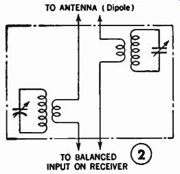
Fig. 7-15. Schematic of typical wavetrap.
Suppression circuits can also take the form of a parallel resonant circuit, which is inserted in the grid-coupling system between the RF and mixer stages; therefore it curbs the mixing action that produces the interference in the IF system.
To construct an effective wave trap, it is first necessary to calculate the frequency of the interfering signal and construct or purchase a trap that can be inserted and tuned until the interference disappears. Booster amplifiers, because of their added selectivity, are also employed to suppress signal interference. It is for this reason that booster amplifiers are sometimes employed in strong-signal areas. The signal is reduced later with a resistance pad.
Impulse-Noise Suppression--Impulse noise originating in electrical appliances such as electric cash registers, office equipment, and shavers can best be suppressed at the source. This is commonly accomplished by the insertion of a small capacitor shunted across the ac line at the input to the device.
For complete noise suppression from large industrial equipment, electrical signs, etc., there are several types of filters on the market consisting of series-inductor and shunt-capacitor combi nations, which prevent RF energy from feeding back to the power line and then radiating or feeding directly into the television or radio receiver.
Because of the tendency of numerous noises to enter the television receiver via the power line, a filter inserted between outlet and receiver, in many instances, will effectively suppress noises emanating from home appliances or industrial equipment operating on the same power line.
It is a well-known fact that neon signs are notorious offenders in television and radio reception disturbances. The flasher device is nothing more than a set of switches, and therefore noise suppression is similar to that employed for other industrial equipment.
Another source of disturbance in neon signs is arcing between connections, particularly in the electrode housing or between cable ends. Again interference may be caused by flickering tubing, an overloaded transformer, faulty insulation, corona discharges between tubing and ground, loose connections, un grounded transformer case, a broker conductor inside the insulation, etc.
When reception interference has been found to be caused by a neon sign, each of these trouble sources should be investigated.
As a general rule, however, it has been found that the employment of filter units across switch contacts and also across the primary winding of the transformer will remedy the trouble. It has also been found effective to install a high-frequency choke properly insulated between the letters of the sign. When filters are installed, it should be remembered that the components employed must be able to withstand the potentials and current that must flow through them.
Perhaps the most important consideration in areas plagued by interference and noise is the choice of antenna and its proper orientation. This consideration, however, has been fully covered in Section 4 and needs no further elaboration.
SUMMARY
Television receivers are operated at a much higher frequency than radio receivers, and the sources of interference are not the same. A television receiver is almost immune to weather-produced interference, whereas radio reception is generally affected by such actions.
Many forms of interference can be identified when viewed on the screen. After they are identified, corrective measures can be applied to eliminate most of them. Some types of interference are not so easily identified, and in some cases there are no known corrective measures. Man-made noise arising from various types of electrical apparatus, such as electric motors and automobile ignition noise, can be partially eliminated by using the right antenna, properly placed.
Interference conditions can generally be corrected by lowering the amount of signal input to the receiver at the frequency that causes the interference. A wave trap may be inserted in series with the antenna, or it may be built into the receiver as a permanent feature.
QUIZ
1. Why are antenna transmission lines twisted?
2. What effects do aircraft have on the TV picture?
3. What are the most common types of TV interference?
4. Explain the Barkhausen oscillator.
5. What is the purpose of the wave trap?
6. What causes local oscillator interference from one TV receiver to another?
7. What causes the venetian-blind effect?