The RF tuner (or front end, as it is sometimes called) is the first section in the television receiver to receive and act upon the composite video signal. There are many types of tuners, but all perform the same basic functions. The block diagram of a television tuner is given in Fig. 8-1.
As indicated by the block diagram, the tuner in a television receiver essentially performs the same functions as the RF amplifier and converter sections of a conventional broadcast or short wave radio. In a television receiver, however, there are many problems not encountered in broadcast radio. These problems complicate the design of the television-receiver RF tuner. These problems are:
1. The broad bandwidth of the television channel. Proper television reception requires that a band of frequencies 6 MHz wide be accepted and amplified. For broadcast radio, the required bandwidth is only a few kilohertz.
2. The frequency allocations of TV channels (54-88 MHz, 174-216 MHz, and 470-890 MHz) necessitate special coup ling circuits. Component and lead placement are critical.
Figure 8-2 shows a typical VHF frequency-response curve, and Fig. 8-3 shows the chief features of a sweep generator.
3. Input circuits must be properly matched to the impedance of the transmission line and antenna and provide the proper match between the transmission-line impedance and RF amplifier, transistor-input impedance.
4. Even though a wideband response (6 MHz) is desired, many other signals outside the bandwidth of the desired channel must be avoided. Such undesired signals are: (a) Adjacent-channel sound carrier (b) Adjacent-channel video carrier (c) Signals at the intermediate frequency that might be coupled through the RF system (d) Signals from other television or FM stations (e) Overloading of the RF amplifier by strong signals from any type of station
5. The local oscillator signal must be properly isolated from the antenna. This is one of the principal reasons that all television receivers employ RF amplifiers. If the oscillator signal were allowed in the antenna circuit, the antenna would function as a transmitter and radiate the signal to all nearby television receivers, causing severe interference. The amount of radiation permissible is regulated by the FCC. Without an RF amplifier, it is very difficult to suppress oscillator radiation to permissible limits.
TYPES OF RF TUNERS
RF tuners can be classified in two different ways: (1) by type of RF amplifier, which is the principal circuit difference (the various types of RF amplifier circuits will be discussed later); and (2) by the means employed to accomplish channel selection.
Pushbuttons, continuous (variable inductance or variable capacitance), wafer-switch, turret, and disk tuners have been employed. By far the most popular systems, however, are the switch and turret types. Click-stop tuning is now required for UHF applications. A typical miniaturized VHF tuner is shown in Fig. 8-4, and a miniaturized UHF tuner is shown in Fig. 8-5.
RF tuners can also be classified into tube, transistor, and hybrid types. An all-transistor tuner is solid-state throughout. A typical hybrid tuner employs semiconductor devices in the RF, oscillator, and mixer stages but utilizes a special UHF oscillator tube. These variations with which the technician must contend are explained subsequently.
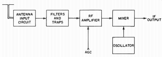
Fig. 8-1. Block diagram of a television RF tuner.
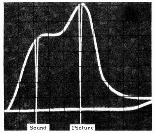
Fig. 8-2. RF response curve with sound- and picture-carrier frequencies marked.
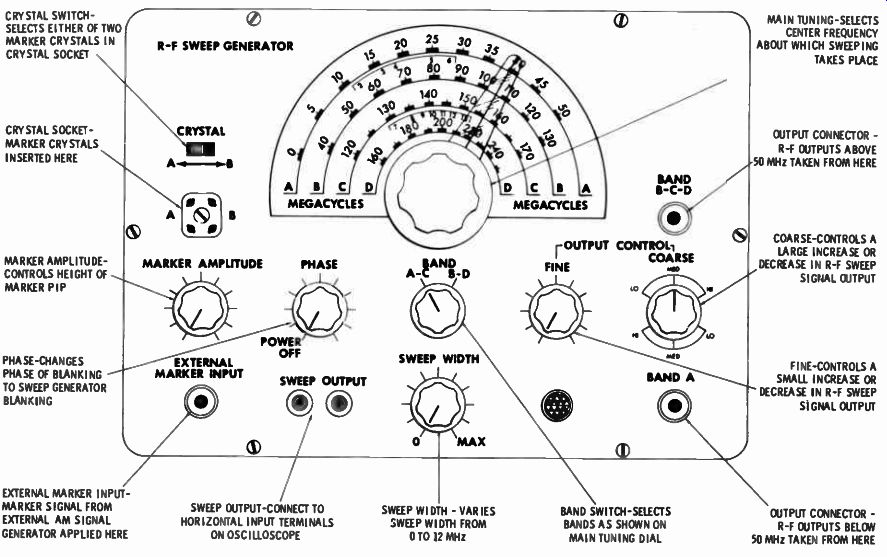
Fig. 8-3. VHF sweep generator used to check frequency-response curves.
Turret Tuners
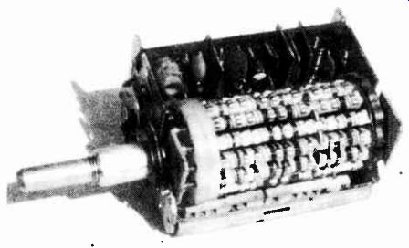
Fig. 8-4. Typical miniaturized VHF tuner.
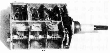
Fig. 8-5. Typical miniaturized UHF tuner.
A typical tube-type turret tuner is shown in Fig. 8-6. The coils employed to tune the RF amplifier input and output, mixer input, and oscillator input are mounted on the individual strips that form the drum. Each coil is connected to the silver-plated contacts on the outside of the strip. These strips then mate with a set of contacts inside the tuner to complete the circuit. For each channel, a separate set of coils is included. As the channel selector shaft is rotated, a different set of coils is switched in for each channel.
Most tuners used in transistor TV receivers are of the turret type. Figure 8-7 depicts the configuration for a VHF transistor tuner. Printed circuitry is often utilized, although metallic chassis construction is employed when optimum low-impedance ground returns are a design goal. A high-pass filter and IF trap are connected in the antenna-input circuit in this example. An alternative interference-rejecting arrangement comprises three tunable traps, as shown in the inset.
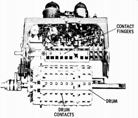
Fig. 8-6. Turret-type tuner.
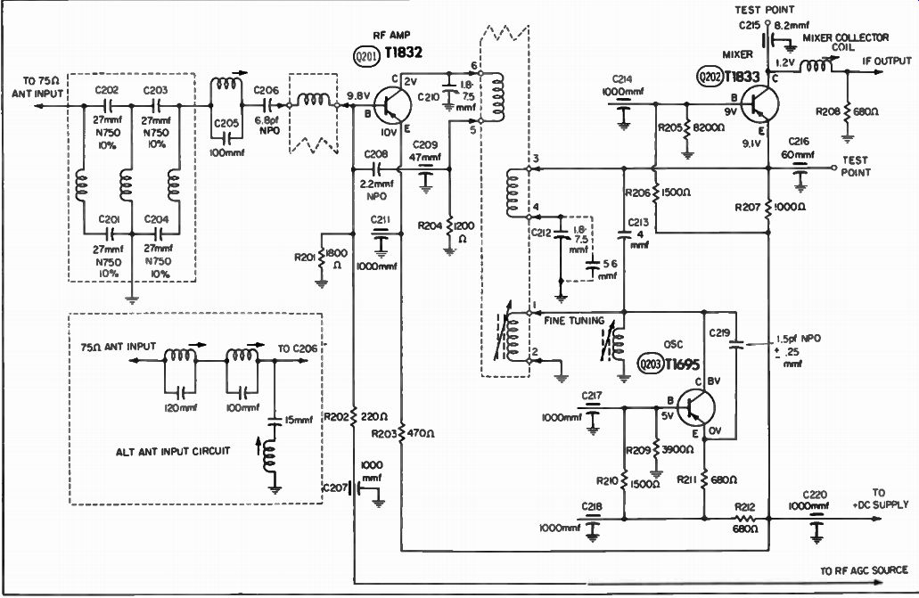
Fig. 8-7. Schematic of a typical turret-type transistor tuner.
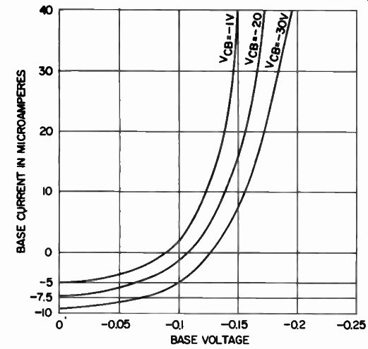
Fig. 8-8.
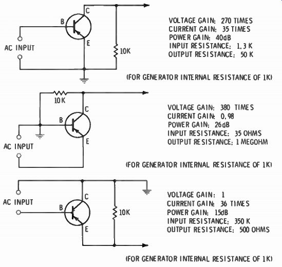
Fig. 8-9. Comparison of typical characteristics of a triode transistor in
three basic amplifier configurations.
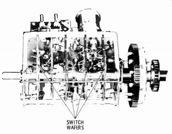
Fig. 8-10. Wafer-switch-type tuner.
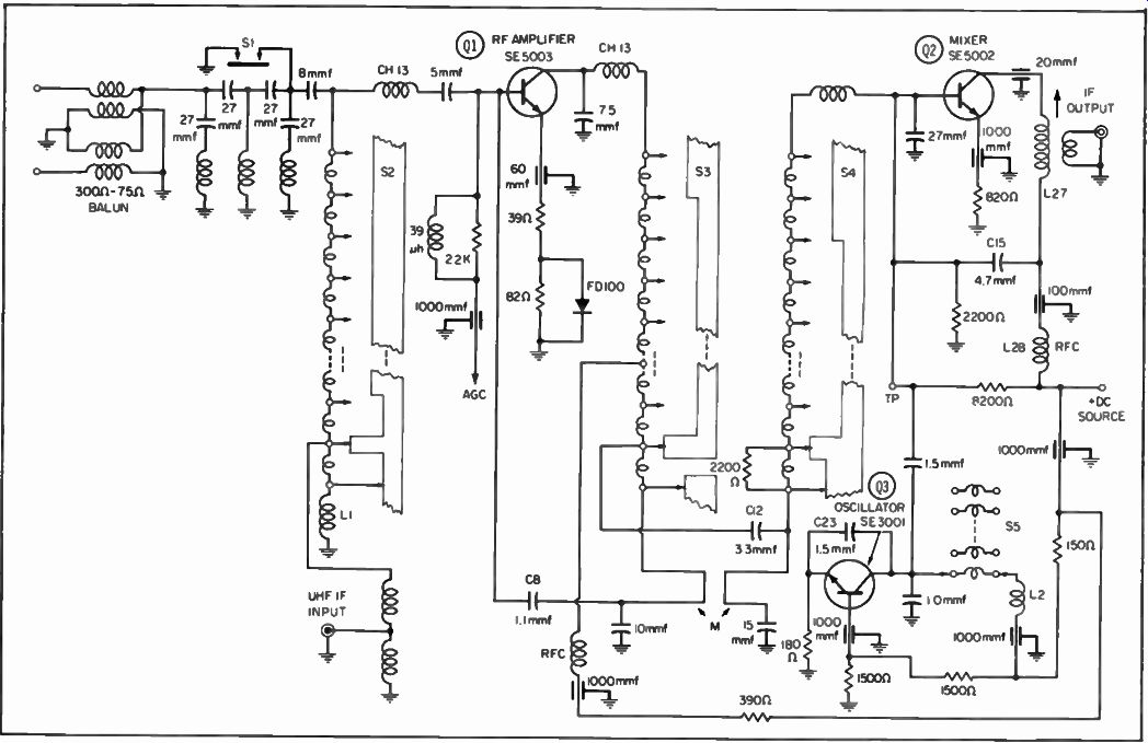
Fig. 8-11. Schematic of typical switch-type tuner.
Neutralization is accomplished by out-of-phase feedback via C208 in Fig. 8-7. Transistor Q201 operates at an average forward bias of 0.2 volt, subject to AGC variation. Since the mixer transistor operates with emitter and collector circuits tuned to different frequencies, neutralization is not required in this stage. The mixer transistor operates at 0.1 volt forward bias because a nonlinear characteristic is required for heterodyne mixer action. Figure 8-8 shows how the emitter-base characteristic has maximum non linearity in the vicinity of 0.1-volt forward bias. Figure 8-9 lists the important characteristics of the three basic bipolar transistor configurations.
Wafer-Switch Tuners
Unlike the turret tuner, individual coils are not employed in wafer-switch tuners (Fig. 8-10). A series of coils are connected between the contacts on each switch deck. As the channel selector shaft is rotated, the inductances are incrementally added or subtracted to tune the desired band. Thus, this type of tuner is often called an incremental inductance tuner. The configuration of a transistor wafer-switch tuner is shown in Fig. 8-11.
Disk Tuners
A disk tuner (Fig. 8-12) combines certain principles of both the turret- and switch-type tuners. Attached to the shaft inside the tuner are two large disks upon which the tuning inductors are arranged. The antenna coils are on the rear disk. A detent mechanism resembling that of the turret tuner is mounted on this disk.
Contact buttons and fingers, like those of the turret tuner, connect the disk to the external circuitry.
An important difference between the turret and disk tuners is that the disk tuner does not have a completely separate set of coils for each channel. There are several sets of basic coils plus incremental inductances, which are switched in series with the basic coils to tune certain channels. However, the coils are broken into more separate groups in the disk tuner than in the typical switch tuner described previously.
All the contact buttons on the under side of the upper disk are arranged in six concentric circles. The buttons in the innermost two circles are connected to the plate coils for the RF amplifier; the middle two are connected to the mixer input circuit; and the outer two are connected to the oscillator coils. A 1.5-µf (micro farad) capacitor connects the low-band RF coils to the corresponding mixer coils.
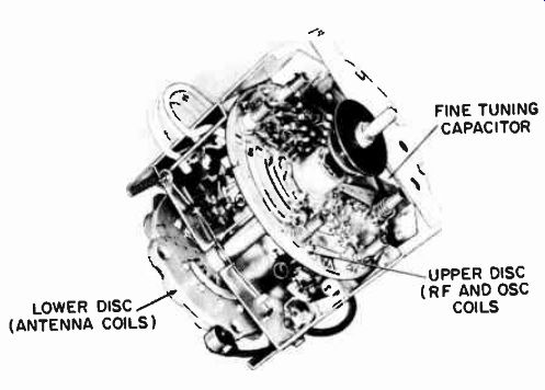
Fig. 8-12. Disk-type tuner.
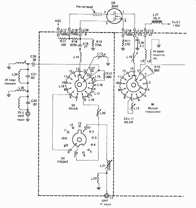
Fig. 8-13. MOSFET-VHF-tuner configuration
The fine-tuning capacitor is located at the top of the tuner (Fig. 8-12). The movable plate is a strip of metal attached to the tuning shaft, and the fixed plate is printed on a small wiring board.
In still smaller versions of the disk tuner, all coils (antenna, RF, and oscillator) for all 12 VHF channels are mounted on one disk.
Connections to the coils are made by spring contacts like those in a turret tuner. Proper positioning of the wheel for each channel is ensured by a detent mechanism like the one in a turret tuner.
A MOSFET-type, VHF-tuner configuration is shown in Fig. 8-13. A dual-gate MOSFET of the N-channel depletion type is utilized in the RF stage. The signal voltage is applied to one gate, and the ACC voltage is applied to the other gate. This ACC voltage normally varies from -5 to + 6.7 volts, depending upon the incoming signal strength. A dual-gate amplifier does not require neutralization. The mixer section in Fig. 8-13 uses a pair of bipolar transistors in a standard cascode circuit. QI operates in the CE mode and drives Q2, which operates in the CB mode.
The oscillator stage uses a bipolar transistor in a Colpitts circuit.
Q4 functions as a varactor diode in an AFC circuit to keep the VHF oscillator from drifting off frequency. The oscillator operates at 41.25 MHz above the sound-carrier frequency. Important characteristics of the basic FET amplifier configurations are listed in Fig. 8-14.
ANTENNA INPUT CIRCUITS
As mentioned previously, the primary purpose of the antenna input circuit is to match the impedance of the antenna to the input impedance of the RF amplifier. Normally a balun (for balanced-unbalanced) is used for impedance matching. In addition, most antenna input circuits also include trap circuits for removing unwanted frequencies from other sources, such as amateur radio and commercial communications.
The circuit of a balun designed for matching a 300-ohm balanced antenna to an unbalanced input is given in Fig. 8-15. At first, the balun appears to be a transformer; however, it is actually two sets of parallel-tuned lines, similar to that obtained from ordinary twin-lead line, constructed in a lumped form to con serve space. They are constructed of extremely fine wire and wound on a coil form or on a ceramic core.
The balun coils are precisely tuned by length so that they are connected for the proper input and output impedances, minimum mismatch, and maximum transfer of energy. Another type of balun is shown in Fig. 8-16. This unit is designed for matching a 75-ohm unbalanced coax lead-in to a 300-ohm balanced input.
Usually various trap circuits are also included in the antenna input. Four examples of typical inputs are shown in Fig. 8-17.
The inputs in Fig. 8-17A and B are for matching balanced antennas to unbalanced tuner inputs, while the inputs in Fig. 8-17C and D are for matching balanced antennas to balanced tuner inputs.
Many other circuits are employed; however, all will resemble those in Fig. 8-17.
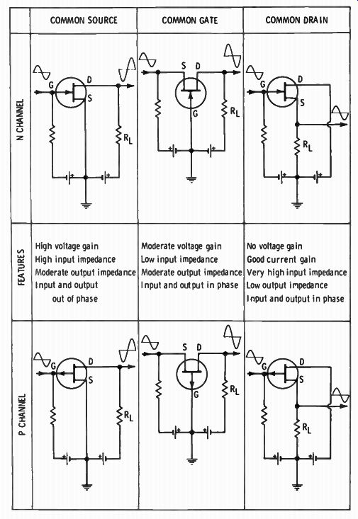
Fig. 8-14. Basic FET circuits.
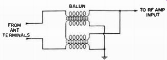
Fig. 8-15. Balum for matching a 300-ohm balanced antenna to a 300-ohm unbalanced
input.

Fig. 8-16. Balun for matching a 75-ohm unbalanced coax lead to a 300 ohm balanced
input.
RF AMPLIFIER CIRCUITS
Unlike radio receivers where the RF amplifier stage is some times omitted, all modern television receivers employ an RF amplifier stage. As mentioned previously, there are two reasons for incorporating an RF amplifier stage. First, the additional gain provided increases the sensitivity of the receiver, which is particularly important where distant stations, which resulting weak signals, must be received. The second reason is that the RF amplifier helps to isolate the oscillator stage from the antenna.
Thus radiation of the oscillator signal from the antenna is reduced.
A widely used RF amplifier configuration is shown in Fig. 8-18.
An unbypassed emitter resistor is used to optimize the signal-to noise (SNR) ratio and to reduce the possibility of cross modulation. Capacitor CN provides neutralization. Forward automatic gain control is used. In other words, as the incoming signal strength increases, the forward bias is increased on the transistor.
In turn, the transistor approaches saturation, and its gain decreases. Forward AGC requires that the value of R3 be at least 1,000 ohms, so that the collector voltage on the transistor de creases substantially as the forward bias is increased.
Transistors used in VHF amplifiers must have a suitably high alpha cutoff frequency. For example, the mesa transistor is often used, as shown in Fig. 8-19. The circuit depicted in Fig. 8-20 shows a typical configuration utilizing the mesa transistor. This type of transistor has a better noise figure, has good gain, and is economical. Much of its merit is due to its low interelectrode capacitance. A typical mesa RF amplifier has a gain of 25 db and a noise figure of 7 db on channel 13, with a gain of 35 db and a noise figure of 5 db on channel 2. This is a slightly higher gain and a lower noise figure than found in RF amplifiers using other types of high-frequency transistors.
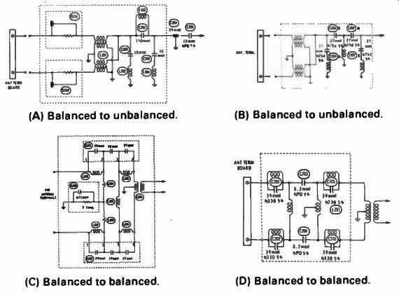
Fig. 8-17. Typical antenna-input circuits.
(A) Balanced to unbalanced; (C) Balanced to balanced; (B) Balanced to unbalanced
(D) Balanced to balanced.
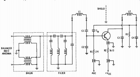
Fig. 8-18. Widely used RF amplifier configuration.
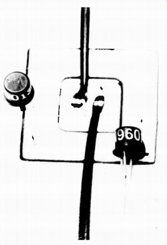
Fig. 8-19. Typical mesa transistor.
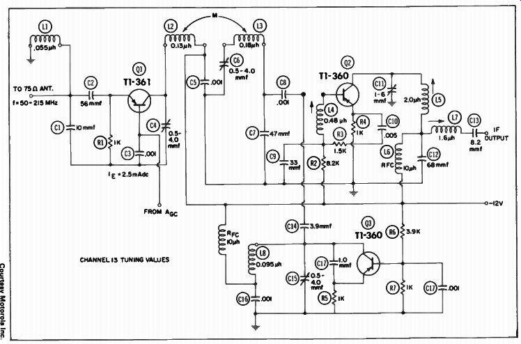
Fig. 8-20. TV tuner with mesa transistors.
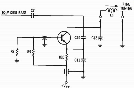
Fig 8-21. Representative local oscillator configuration.
OSCILLATOR CIRCUITS
The purpose of the oscillator is to generate a signal 45.75 MHz above the incoming signal (video) frequency. The incoming signal and the oscillator signal are then mixed to produce the correct IF difference signal.
A typical local oscillator configuration is shown in Fig. 8-21.
Since a common-base transistor amplifier is generally regenerative at VHF, this mode of operation is suitable for an oscillator arrangement. Positive feedback is provided via C10 and C11.
The value of C7 determines the level of injection voltage to the mixer. About 0.15 volt of oscillator signal into the mixer provides maximum gain. The fine-tuning slug has a range of greater than ±1.5 MHz. Use of slug tuning in each oscillator coil permits the use of a preset fine-tuning arrangement.
Quite a few RF tuners include an automatic fine-tuning system, which comprises an error sensor and a control device. A typical error sensor consists of a discriminator circuit, as shown in Fig. 8-22. A sample of the IF signal is fed to the discriminator, which has a frequency response as shown in Fig. 8-23. One of the discriminator diodes is forward-biased, and the other is reverse biased. This provides a push-push action so that both the picture and sound carriers assist in producing a corrective output voltage, which is applied to a varactor diode, as shown in Fig. 8-24.
As the correction voltage varies from 1 to 8 volts, the varactor capacitance varies from 15 to 6 pF (picofarads) to return the oscillator to its correct frequency.
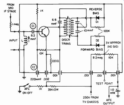
Fig. 8-22. Discriminator circuit used for automatic fine-tuning control.
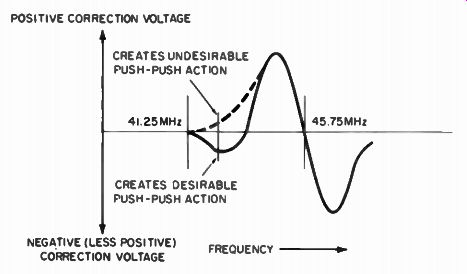
Fig 8-23. Discriminator diodes in Fig.8-22, biased to modify the conventional
response curve.
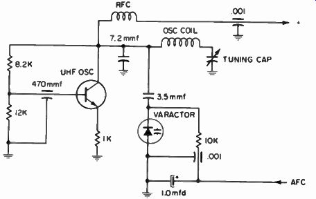
Fig. 8-24. Varactor that operates as a variable capacitor.
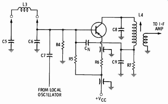
Fig. 8-25. Representative mixer configuration.
MIXER CIRCUITS
A representative mixer configuration is shown in Fig. 8-25. It is similar to an amplifier arrangement, except that the base and emitter of the transistor are at the same de potential. In other words, the base-emitter junction operates as a rectifying diode, thereby obtaining heterodyne action. Neutralization is provided by CN to ensure operating stability. A 50-ohm output impedance is provided to match a 50-ohm coaxial cable to the IF strip. The de collector voltage is chosen at a value that provides maximum stage gain.
Figure 8-26 shows the circuit for a typical transistor mixer stage, with the associated RF and oscillator sections. Tetrode transistors are shown in this circuit. A tetrode transistor is also called a double-base transistor. The basic arrangement is shown in Fig. 8-27. Bias voltage Vgg constricts the base current flow at a comparatively small cross section. In turn, the transit time is shorter through the base, and the transistor is more efficient at very high frequencies. The mixer stage gain in Fig. 8-26 is about 7 db on channel 13.
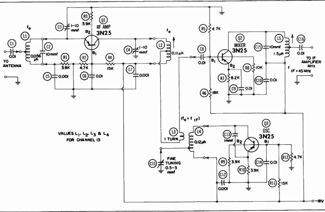
Fig. 8-26. VHF mixer with RF amplifier and oscillator.
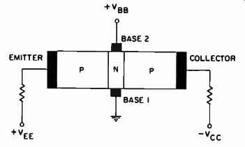
Fig. 8-27. Basic tetrode transistor arrangement.
UHF TUNERS
All the tuners described up to this point will tune only the 12 VHF channels; they will not tune the 70 UHF channels. There fore some means must be provided to receive these channels.
Two methods are employed: the use of two tuners, one for VHF and one for UHF; or the insertion of individual UHF strips in place of unused channels on turret-type tuners.
VHF and UHF Tuners The most common method of providing reception of all 82 channels is to use a 13-position VHF tuner and a separate UHF tuner. Figure 8-28 shows the arrangement of a transistor UHF tuner employing a semiconductor-diode mixer stage. The output from the mixer is fed to the VHF tuner, which operates as the first IF section in the receiver. About 5 mA are drawn from the de supply by the UHF oscillator. The mixer output frequency is usually adjusted for operation on channel 6 of the VHF tuner. A special type of silicon transistor is used in the oscillator circuit because the UHF-range extends from 470 to 890 MHz.
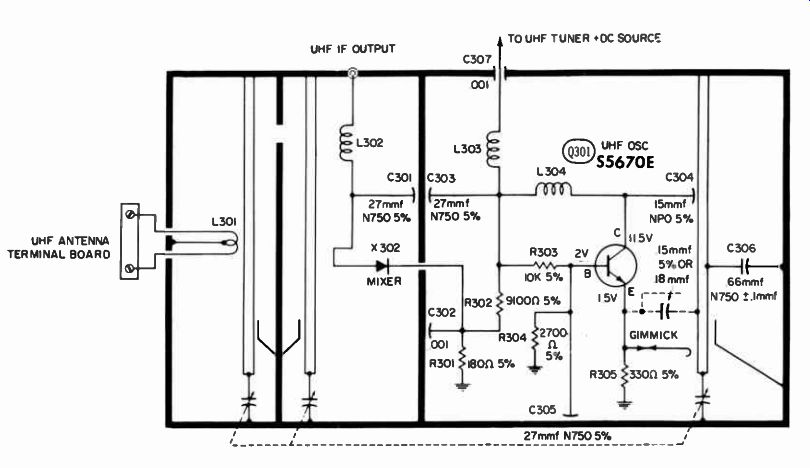
Fig. 8-28. Schematic of typical UHF tuner.
SUMMARY
RF tuners can be classified in two different ways: by the principal circuit difference and by construction, such as pushbutton, wafer switch, turret, and disk type.
Unlike radio receivers where the RF amplifier stage is some times omitted, all television receivers employ an RF amplifier stage (1) to give additional gain, which provides increased sensitivity, and (2) to help isolate the oscillator stage from the antenna.
The purpose of the oscillator is to generate a signal 45.75 MHz above the incoming-signal frequency. The incoming signal and the oscillator signal are then mixed to produce the correct IF difference signal. The Mixer stage mixes the signal from the RF amplifier stage and the signal from the mixer stage and combines them. Since these two frequencies are separated by 45.75 MHz, the IF signal, at this 45.75 MHz frequency, appears in the output circuit where it is coupled to the IF amplifier.
QUIZ
1. What are the frequency allocations for TV channels?
2. Name the various types of television VHF tuners.
3. What purpose does a balun serve in the antenna circuit?
4. What is the purpose of an RF amplifier stage in the television receiver?
5. What is the purpose of the oscillator?
6. What is the purpose of the fine-tuning control?